- 1Smart Grids Research Group, Center of Research Excellence in Renewable Energy and Power Systems, King Abdulaziz University, Jeddah, Saudi Arabia
- 2Department of Electrical and Computer Engineering, King Abdulaziz University, Jeddah, Saudi Arabia
This paper presents a distributed consensus-based voltage and frequency control (VFC) strategy for isolated microgrids with distributed energy resources (DERs) and induction motor loads. The proposed controller coordinates the DERs to regulate microgrid frequency and voltage while mitigating fault-induced delayed voltage recovery (FIDVR), a phenomenon where system voltage remains depressed for several seconds after fault clearance due to induction motor stalling. The VFC loop adjusts DER voltage setpoints based on frequency deviation and voltage level to regulate voltage and mitigate FIDVR events, while the active power control loop maintains frequency stability by coordinating active power sharing among DERs and compensating for the constant power load behavior of stalled induction motors. A proximity-based reactive power support prioritization and a distributed voltage estimator enhance the controller’s response to FIDVR events. Coordination between the VFC and active power control loops is achieved through adaptive gain adjustment and a voltage recovery coordination term. Simulation results demonstrate the effectiveness of the proposed controller in maintaining microgrid stability, ensuring fast voltage recovery, and providing robust performance under various operating conditions, including communication delays and different fault durations.
1 Introduction
Microgrids are gaining popularity as alternatives to traditional centralized power systems, addressing environmental and economic concerns. These local networks of distributed energy resources (DERs) and loads generate power to meet local demand, but the complex mix of energy sources and technologies presents challenges for operators and planners (Olivares et al., 2014). The intermittent behavior of DERs often leads to rapid frequency excursions during disturbances, especially when the microgrid is isolated. Thus, coordinated frequency control through distributed techniques is crucial for ensuring microgrid stability (Bidram, 2017).
Numerous studies have explored distributed and decentralized control techniques for frequency control in microgrids. Some focus on voltage regulation-based frequency control, while others investigate specific aspects of microgrid dynamics or applications. This paper presents an enhanced operational control scheme that effectively manages isolated microgrids, addressing both frequency regulation and fault-induced delayed voltage recovery (FIDVR). The literature review analyzes the advantages of this study compared to existing research.
Farrokhabadi et al. (2017) presents a frequency control mechanism for isolated microgrids based on voltage regulation, but it lacks co-optimization with active power sharing control and a precise mechanism to mitigate FIDVR events. Similarly, (Farrokhabadi et al., 2016) introduces a novel voltage-based controller for frequency control in inverter-based isolated microgrids, offering advantages such as decreased system dependency on energy storage and higher penetration of renewable energy. However, it does not manage intricate microgrid dynamics and disturbances. The study by Farrokhabadi et al. (2021) explores the use of optimal voltage-based frequency control in islanded microgrids and demonstrates the robustness of the proposed VFC controller. However, the study does not consider the issue of power-sharing among DERs or provide a dedicated voltage control mode specifically designed to handle fault-induced delayed voltage recovery (FIDVR) events. Furthermore, the impact of VFC on microgrid stability in the presence of induction motor loads is not investigated in these studies.
Recent advances in distributed control strategies have focused on finite-time and predefined-time convergence to enhance the dynamic performance of microgrids. In Xu et al. (2019), an optimal distributed control strategy is proposed for the coordination of multiple distributed generators in an islanded microgrid, employing a finite-time secondary frequency control approach to eliminate frequency deviation and maintain accurate active power sharing. However, the approach does not address FIDVR events or the coordination between voltage control and reactive power sharing during such disturbances.
Similarly, (Choi et al., 2022) presents a distributed finite-time event-triggered secondary frequency and voltage control for islanded AC microgrids, effectively performing frequency restoration and voltage regulation while sharing active and reactive power among distributed generators. The event-triggered communication reduces the communication burden, but the study does not consider the mitigation of FIDVR events or the impact of induction motor loads on voltage stability.
In Huang et al. (2023), a novel distributed fractional-order predefined-time sliding mode controller is proposed as a secondary controller for islanded AC microgrids. The controller ensures that frequency and estimated average voltage converge to reference values within a predefined time, enhancing dynamic performance. Nevertheless, the study does not address FIDVR mitigation or the coordination between voltage control and reactive power sharing in the presence of induction motor loads.
Other studies focus on specific aspects of microgrid problems, such as utilizing DER smart inverters and FACTS devices for FIDVR mitigation. In Wang and de León (2020), smart inverters with voltage ride-through and var injection capabilities are exploited for the mitigation of FIDVR in distribution systems, showing that DER penetration levels significantly affect mitigation success. However, the study is centered on distribution systems rather than isolated microgrids and does not propose a coordinated control strategy among DERs.
Paredes et al. (2023) proposes an approach to incorporate flexible AC transmission system (FACTS) devices, such as SVC and DSTATCOM, into microgrids as reactive power supply resources for improving dynamic voltage stability and mitigating FIDVR. While effective in enhancing voltage stability, the solution relies on additional hardware infrastructure and does not leverage the existing DER capabilities for coordinated voltage and frequency control.
A model-free voltage control approach is presented in Park and Olama (2021) to mitigate motor stalling and FIDVR in smart grids, utilizing an intelligent PID controller without requiring complex dynamic models. This method simplifies implementation and reduces computational costs but does not consider the coordination among multiple DERs in a microgrid or address active power sharing and frequency regulation.
In Mohiuddin and Qi (2022), an optimal distributed voltage control for grid-forming inverters in islanded AC microgrids is proposed, formulating an optimization problem that balances voltage regulation and reactive power sharing. While the approach addresses coordinated voltage control and reactive power sharing, it does not specifically target FIDVR events or consider the impact of induction motor loads on microgrid stability.
Other studies focus on specific aspects of microgrid problems. Nayeripour et al. (2018) explores the challenge of protecting load buses serving three-phase induction motors using dynamic state estimation, but does not consider frequency regulation and FIDVR aspects. Benali et al. (2018) investigates the impact of induction motor load on the dynamic voltage stability of an isolated microgrid during faults and proposes a reactive power support control strategy using photovoltaic systems to mitigate dynamic voltage instability. Hossain et al. (2019) examines the starting capability of diesel generators and battery energy storage systems (BESS) in islanded microgrids with induction motors, proposing a Starting Capability Index (SCI) to assess the system’s starting capability and improve dynamic performance, but does not address broader frequency regulation and FIDVR management capabilities.
Ling et al. (2021) presents a transient stability analysis of an induction motor-load system considering stator flux dynamics, while (Gu et al., 2022) investigates the transient stability of an induction motor-load system under voltage sag conditions, proposing a new method to analyze the system’s transient stability. However, these studies do not provide a holistic and adaptive control strategy for managing intricate microgrid dynamics and disturbances in the context of frequency regulation and FIDVR scenarios.
Alghamdi (2022b) presents a fuzzy-logic-based voltage frequency control and adaptive inertia controller for improving the frequency response of a virtual synchronous generator (VSG) in an isolated microgrid system, but lacks seamless transition between control modes and a specialized voltage control mode for FIDVR events. Alghamdi (2022a) proposes a hierarchical distributed consensus control method for frequency regulation in isolated microgrids using voltage frequency control and active power regulation, but does not address FIDVR events or consider the impact of induction motor loads on microgrid stability.
The proposed distributed consensus-based voltage and frequency control (VFC) strategy offers significant advantages over existing VFC techniques. It addresses several gaps in the current literature and provides innovative solutions to enhance microgrid stability and resilience. Based on the reviewed literature, several limitations in existing microgrid control strategies can be identified:
1. Limited consideration of FIDVR events in VFC schemes.
2. Lack of coordination between VFC and active power control in distributed control architectures.
3. Insufficient attention to the impact of communication delays on distributed control performance.
4. Absence of adaptive control mechanisms to handle varying fault durations.
This paper addresses these gaps through the following key contributions:
1. A novel distributed consensus-based VFC strategy that effectively handles FIDVR events in isolated microgrids with induction motor loads. This strategy incorporates a specialized voltage control mode that addresses FIDVR events, introducing a proximity-based reactive power support prioritization and a distributed voltage estimator. This enhances the controller’s response to FIDVR events and provides an accurate representation of the microgrid voltage profile, ensuring faster recovery times and improved voltage stability.
2. An adaptive gain adjustment mechanism in the active power control loop to maintain frequency stability and compensate for the constant power load behavior of stalled induction motors during FIDVR events. The proposed controller achieves effective coordination between the VFC and active power control through this mechanism and the inclusion of a voltage recovery coordination term in the active power setpoint calculation. This enables the active power control loop to provide a fast and robust response to frequency deviations caused by the constant power load behavior of stalled induction motors during FIDVR events, maintaining frequency stability while the VFC focuses on voltage recovery.
3. A comprehensive analysis of the proposed controller’s performance under various communication delay scenarios, demonstrating its robustness in realistic microgrid applications.
4. An in-depth investigation of the controller’s effectiveness in handling different fault durations, showcasing its adaptability to various disturbance conditions.
The remainder of this paper is organized as follows: Section 2 discusses the modeling of microgrid components, including static and dynamic loads, with a focus on the behavior of induction motor loads during FIDVR events. Section 3 introduces the proposed distributed consensus-based VFC strategy, detailing the voltage control loop, active power control loop, proximity-based reactive power support prioritization, and adaptive gain adjustment mechanism. Section 4 presents the simulation results and discussion, demonstrating the effectiveness of the proposed controller in maintaining microgrid stability, ensuring fast voltage recovery, and providing robust performance under various operating conditions. This section also investigates the impact of fault duration and communication delays on the controller’s performance. Finally, Section 5 summarizes the main conclusions and highlights the significance of the proposed distributed consensus-based VFC strategy in enhancing the stability and resilience of isolated microgrids with induction motor loads.
2 Modeling and frequency regulation in microgrid architectures
Isolated microgrids face challenges in maintaining stable voltage and frequency due to the intermittent nature of renewable energy sources (RESs) and potential supply-demand imbalances. This paper focuses on developing a distributed consensus-based VFC strategy that operates at the primary and secondary control levels to ensure stable microgrid operation and mitigate fault-induced delayed voltage recovery (FIDVR) events.
The microgrid under study consists of diesel generators, battery energy storage systems (BESS), wind turbines, and dynamic loads such as induction motors. The diesel generators and BESS are modeled as grid-forming units, while the wind turbines are modeled as grid-following units. The induction motor loads are represented using a full-order wound rotor induction machine model to capture their dynamic behavior and potential for causing FIDVR events.
The proposed VFC strategy coordinates the control actions of the DERs to maintain stable voltage and frequency profiles, even in the presence of disturbances. By leveraging a distributed consensus approach, the VFC strategy enables efficient information exchange among the DERs and facilitates a coordinated response to mitigate FIDVR events and ensure reliable microgrid operation.
2.1 Static load modeling
In this study, the microgrid includes static loads that are modeled using an exponential voltage-dependent load model. This model captures the relationship between load demand and system voltage, as described by Equations 1, 2. Alghamdi and Cañizares (2021):
In these equations,
The exponents
The voltage-dependent behavior of these static loads affects the power balance in the microgrid. As the system voltage decreases, the power consumption of these loads also decreases, and vice versa. This characteristic has implications for frequency regulation, as changes in voltage can influence the system’s frequency through the load demand.
2.2 Induction motor loads and FIDVR
Induction motor loads constitute a significant portion of the load in microgrids and are a primary cause of fault-induced delayed voltage recovery (FIDVR) events due to their stalling behavior during voltage sags (Stefopoulos and Meliopoulos, 2006). In order to accurately study the impact of induction motor loads on FIDVR in microgrids, this paper utilizes a full-order wound rotor induction machine model provided by the PSCAD simulation software PSC (Wound rotor induction machine, 2023).
2.2.1 Dynamic model of the induction motor
The full-order wound rotor induction machine model represents the detailed electrical and mechanical dynamics of the induction motor, accounting for both the stator and rotor circuits as well as the mechanical dynamics of the rotor. The model is based on the following equations in the synchronous reference frame (Krause et al., 2013; Chapman, 2011).
2.2.1.1 Stator voltage equations
The q-axis and d-axis stator voltage dynamics are given by Equations 3 and 4, respectively.
2.2.1.2 Rotor voltage equations
Likewise, the q-axis and d-axis rotor voltage dynamics are formulated in Equations 5 and 6.
2.2.1.3 Flux Linkage equations
The flux linkage relationships are shown in Equations 7, 8, 9, and 10, capturing stator–rotor coupling.
2.2.1.4 Mechanical Equation
Equation 11 governs the mechanical dynamics of the rotor speed (ωr) based on the torque imbalance.
2.2.1.5 Electromagnetic torque
The electromagnetic torque (Te) is computed as shown in Equation 12, relating stator flux linkages and currents.
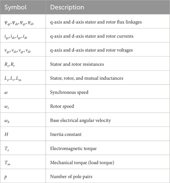
The definitions of the variables and parameters used in the above equations are listed in Table 1.
2.2.2 Behavior during FIDVR events
During voltage sags caused by faults, the reduced terminal voltage leads to a significant drop in the electromagnetic torque
When the fault is cleared and voltage is restored, the stalled induction motor attempts to reaccelerate, drawing a large inrush current and a substantial amount of reactive power due to the low rotor speed and high slip. This excessive reactive power demand can prevent the system voltage from recovering quickly, resulting in FIDVR.
By modeling the induction motor using the detailed equations presented above, we can simulate its dynamic response during faults and voltage recovery, capturing the stalling behavior and its impact on the microgrid voltage profile.
2.2.3 Impact on microgrid stability
The stalling and reaccelerating behavior of induction motors during and after faults poses significant challenges for microgrid stability. The prolonged voltage depression and increased reactive power demand can lead to:
2.2.4 Need for advanced control strategies
Addressing the challenges posed by induction motor loads during FIDVR events necessitates the development of advanced control strategies that can:
These control strategies are critical for ensuring the reliable operation of isolated microgrids with significant induction motor loads. In the following sections, we will introduce and discuss the proposed distributed consensus-based voltage and frequency control strategy designed to tackle these challenges.
2.3 Diesel generators (diesel units)
Diesel generators play a crucial role in isolated microgrids, serving as reliable energy sources capable of providing continuous, uninterruptible power to meet the demand and facilitating frequency and voltage regulation. Diesel generators offer multiple advantages, such as their ability to start quickly, their dispatchability, and their capability of operating over a wide range of loading conditions. These characteristics render diesel generators particularly valuable in isolated microgrids, where other energy sources like renewable energy sources (RESs) can be intermittent and may exhibit unpredictable fluctuations (Vandoorn et al., 2011).
In isolated microgrids, diesel generators form an essential part of the primary control, responsible for maintaining the grid frequency and voltage profiles within acceptable limits. Since the diesel generators are coupled to the microgrid through their synchronous generators, their rotational speed is directly related to the system frequency. Consequently, diesel generators can adjust their mechanical input power to counteract variations in frequency due to mismatches between supply and demand, thus assisting in frequency control.
In isolated microgrids, Equation 13 describes the diesel generator’s swing equation, relating rotor inertia
where
The researchers referenced in Yeager and Willis (1993) have meticulously developed a dynamic model of a diesel generator that is tailored to perform optimally in time-domain simulations. This model is validated by its alignment with an actual field model. In the mentioned study, a comprehensive model is utilized, incorporating both the governor and exciter models. The gains in this model are aptly calibrated to the test system under examination.
Of particular significance is the choice of control mode for the governor model, which is set to Droop Mode as opposed to Isochronous Mode. Droop control is a widely used method for frequency regulation in power systems. It allows load sharing in multiple generator setups and maintains system stability under varying load conditions. The operation of the droop control governor can be quantitively represented by the droop control equation.
Consider, for instance, the following droop control equation as stated in Bevrani (2017):
Here,
2.4 BESS model
In microgrids, battery energy storage systems (BESSs) play a crucial role in managing the rapid fluctuations in the output power of renewable energy sources, such as solar and wind generators (Olivares et al., 2014). BESSs are integrated into the microgrid through voltage source converters (VSCs), which enable them to respond quickly to changes in the system’s frequency by delivering active power. This fast response is essential for maintaining the stability of the microgrid, as the dynamics of BESSs are significantly faster than those of conventional generators like diesel engines.
In this study, the BESS operates in a grid-feeding control mode, where it injects specified amounts of active and reactive power into the microgrid. The control strategy involves calculating the reference currents needed to achieve the desired power injection.
2.4.1 Mathematical model of the BESS operating in grid-feeding mode
The instantaneous active and reactive power injected by the BESS are calculated using Equation 15, which relies on the measured grid-side voltages and currents (Teodorescu, 2011; Yazdani, 2010):
where:
To obtain the fundamental components of active and reactive power, the instantaneous powers
Alternatively, the d–q reference currents are obtained from Equation 17, which uses
Equation 18 uses the PI-based current control loop to generate the voltage references
Where
The feed-forward terms
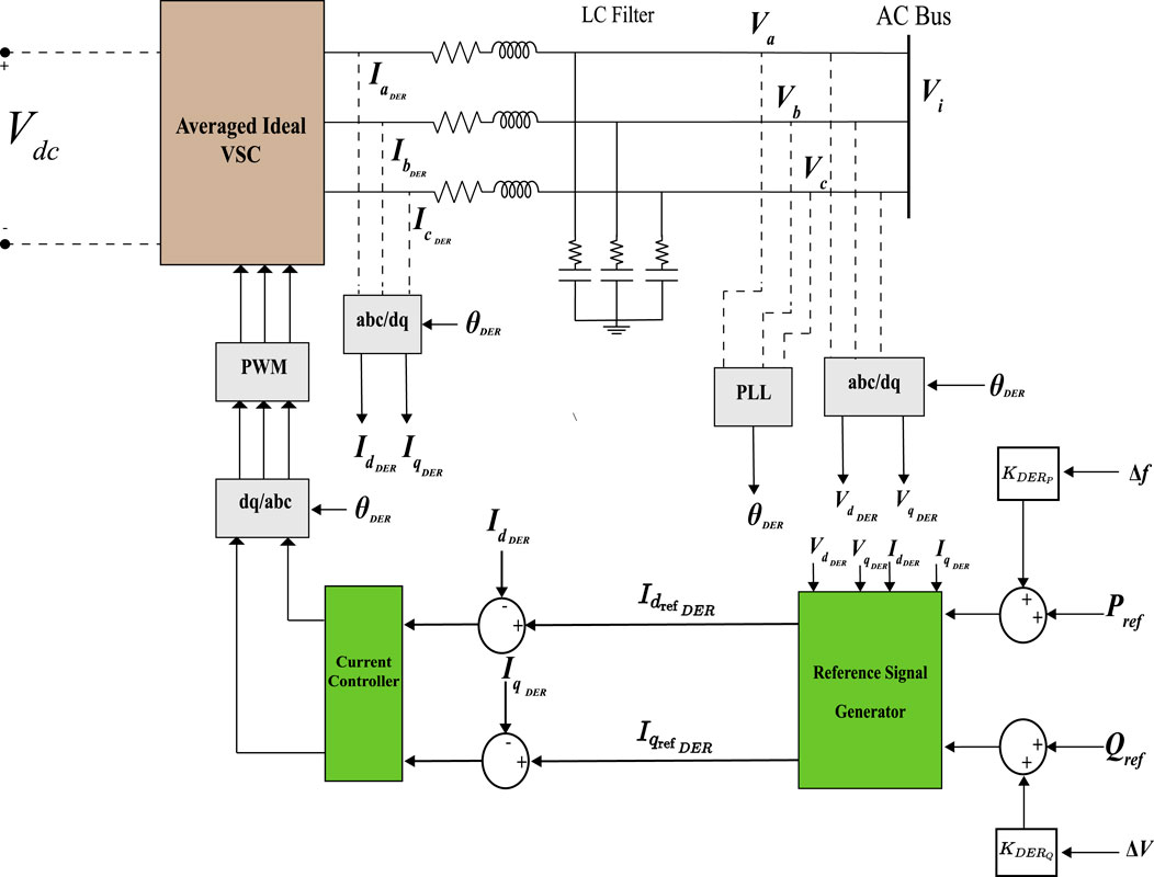
Figure 1. BESS and wind generator VSC average model. (Reprinted/adapted with permission from Alghamdi and Cañizares (2021). © 2021 IEEE).
2.4.2 Controller design and stability considerations
The controllers are tuned using well-established methodologies, such as those described in Teodorescu (2011); Gole et al. (2005), to optimize the performance of the BESS. The tuning process involves selecting appropriate values for the PI controller gains (
The stability and reliability of the BESS under challenging conditions are further enhanced through careful tuning of the phase-locked loop (PLL), as suggested by Yazdani (2010). This process minimizes the effects of unbalanced and harmonically distorted voltages. Additionally, modal estimation methodologies for worst-case scenarios, based on small-signal analysis (Nasr-Azadani et al., 2014), inform the tuning approach, enhancing the BESS’s performance in adverse situations.
2.4.3 Integration into the microgrid
By incorporating this well-designed and properly tuned BESS model operating in grid-feeding mode, the microgrid can effectively manage the variability of renewable energy sources and maintain stable voltage and frequency profiles, even in the presence of rapid power fluctuations.
2.5 Wind generator model
The model for the Type 4 wind generators (WGs) with a voltage source converter (VSC) interface operates similarly to the BESS converter described in Section 2.4. The control strategy for the WG also follows the grid-feeding control mode, where it provides active and reactive power according to reference values. However, unlike the BESS, the wind generator is set to operate at unity power factor, meaning that it provides only active power and does not contribute to reactive power support.
The primary difference from the BESS model is in how the active power reference is determined. In the wind generator model, the active power reference
where
Since the wind turbine operates at unity power factor, the reactive power reference is set to zero, i.e.,
3 Proposed distributed consensus-based voltage and frequency control
This section introduces a distributed consensus-based VFC strategy for isolated microgrids, extending the work in Nasirian et al. (2016); Alghamdi (2022a). The approach integrates primary and secondary control by regulating DERs’ active and reactive power outputs. A specialized voltage control mode is incorporated to manage fault-induced delayed voltage recovery (FIDVR) events, ensuring seamless coordination between active power sharing and frequency regulation.
The key features of the proposed distributed VFC strategy include:
The proposed distributed VFC strategy aims to improve the microgrid’s performance in terms of frequency regulation, voltage stability, and FIDVR mitigation, while ensuring efficient power sharing among DERs. The following subsections provide a detailed description of the proposed control architecture and its key components.
3.1 Communication graph
The proposed distributed consensus-based VFC scheme relies on a communication graph that enables information exchange among the DERs within the microgrid. The communication graph is represented by
The adjacency matrix
To ensure robustness against communication link failures, the proposed communication architecture employs spanning trees, which maintain graph connectivity even during a single link outage. This approach enhances the reliability and resilience of the distributed VFC scheme, ensuring uninterrupted coordination among the DERs.
The communication graph plays a crucial role in the distributed consensus-based VFC scheme, enabling the exchange of voltage, frequency, and power information among the DERs. This information exchange facilitates the coordination of the DERs’ output powers and the implementation of the proposed control algorithms, ultimately leading to improved voltage and frequency regulation, reactive power sharing, and FIDVR mitigation in the microgrid.
3.2 Voltage control loop
The proposed controller coordinates DERs to regulate microgrid frequencies through active power control and VFC, while addressing FIDVR events. It incorporates loops for DER power output regulation, considering voltage-dependent load coupling. A power-sharing mechanism ensures coordination between distributed active power and voltage controllers.
Using an exponential model for microgrid loads, a distributed consensus controller governs frequency by adjusting DER voltage setpoints. To address unequal voltage distribution and improve FIDVR response, the proposed scheme tackles reactive power sharing issues caused by varying DER-to-common point impedances. The distributed control approach is governed by Equations 20, 21. Equation 20 defines
where
The VFC controller adjusts the voltage setpoints of the DERs based on the frequency deviation and voltage level, subject to the following limits:
As shown in Equation 22,
where the microgrid’s minimum and maximum tolerable voltages are denoted by
The controller operates based on the frequency deviation and voltage level, as summarized in Table 2. During normal conditions (i.e., when the voltage level is within limits),
The distributed consensus VFC incorporates
where
In Equation 23, the VFC incorporates two terms: one comparing
3.2.1 Proximity-based reactive power support prioritization
To enhance the controller’s response to FIDVR events, a proximity-based reactive power support prioritization mechanism is implemented. This mechanism assigns higher reactive power support priority to DERs that are electrically closer to the fault location, enabling them to contribute more effectively to mitigating voltage sags during FIDVR events.
This is achieved by introducing a proximity factor,
Calculation of the Proximity Factor
The proximity factor
1. Local Voltage Sag Calculation:
As defined by Equation 24, the local voltage sag
where
2. Information Sharing and Distributed Max-Consensus Algorithm:
DERs share their local voltage sag measurements with their neighboring DERs according to the communication topology defined by the adjacency matrix
where
Equation 26 shows that
3. Proximity Factor Calculation:
Next, each DER computes its proximity factor
This ratio provides a normalized measure of how close each DER is to the fault location.
By incorporating the proximity factor into the reactive power sharing mechanism, the controller ensures that DERs closer to the fault contribute more reactive power, which is essential for faster voltage recovery during FIDVR events.
3.2.2 Integration into the voltage control loop
The proximity-based reactive power support prioritization is integrated into the distributed consensus VFC through the reactive power support factors
This approach enhances the effectiveness of the VFC by:
The distributed nature of the algorithm ensures scalability and robustness, as each DER only requires local measurements and communication with neighboring DERs.
3.2.3 Distributed voltage estimator
The estimated global average voltage
where
The distributed voltage estimator not only assists in frequency regulation but also plays a crucial role in the proximity-based reactive power support prioritization by providing accurate voltage information required for calculating the proximity factors.
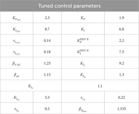
The detailed discussion on tuning the control parameters, including
3.3 Distributed consensus active power coordination with FIDVR consideration
The proposed distributed active power coordination operates in conjunction with the distributed VFC described in Section 3.2. While both controllers use the frequency deviation term
The distributed consensus method for active power coordination is defined by Equations 29, 30, 31, and 32. Equation 29 sets the DER active power reference, while Equations 30 and 31 adapt the control gains under low-voltage conditions.
Finally, Equation 32 coordinates local power flow references among DERs in a distributed manner.
where
Proper tuning of control parameters ensures coordination between the active power controllers and VFC. The gains of the VFC (
However, during FIDVR events, an adaptive gain adjustment mechanism is triggered in the active power control loop to maintain the frequency of the system and counteract the behavior of constant power loads, especially stalled induction motor loads. When the estimated global average voltage
When
By implementing this adaptive gain adjustment mechanism, the proposed active power control loop effectively coordinates with the VFC loop to maintain frequency stability and counteract the impact of constant power loads during FIDVR events, while also providing a stable and sustained response under normal operating conditions.
In Equation 32, neighboring DERs communicate output active powers to local DER
The proposed scheme coordinates distributed VFC and active power control through parameter tuning. This maintains frequency stability during severe disruptions while providing fast regulation. The voltage recovery coordination term enhances FIDVR event support, ensuring a coordinated response within microgrid voltage constraints.
A summarized block diagram of the entire distributed consensus-based voltage and frequency control (VFC) strategy is illustrated in Figure 2, showing how the various loops, estimators, and communications interconnect.
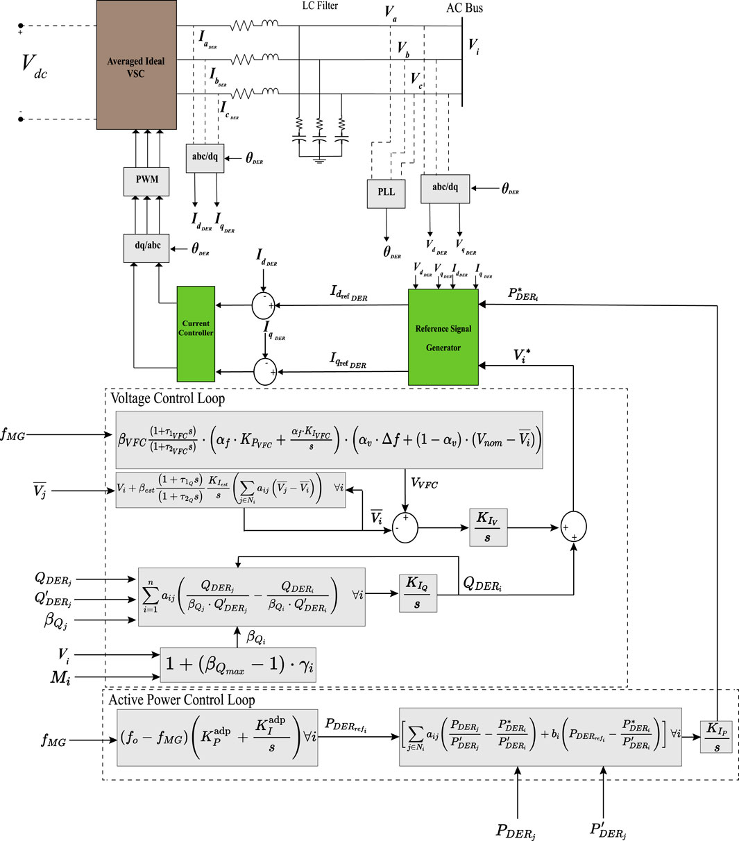
Figure 2. The proposed distributed consensus-based voltage and frequency control strategy implementation.
4 Simulation results and discussion
4.1 Microgrid test system
The modified CIGRE benchmark microgrid, which has been widely used in various studies (Farrokhabadi et al., 2018; Farrokhabadi et al., 2017; Solanki et al., 2017; Solanki et al., 2019; Farrokhabadi et al., 2016), was employed to test, validate, and compare the performance of the proposed distributed consensus-based VFC scheme described in Section 3. The microgrid topology, as illustrated in Figure 3, was implemented in PSCAD for time-domain simulations, while MATLAB was used to conduct small-perturbation analysis. Using a 12-core CPU (average 4.8 GHz per core) and 32 GB RAM, the simulations were conducted.
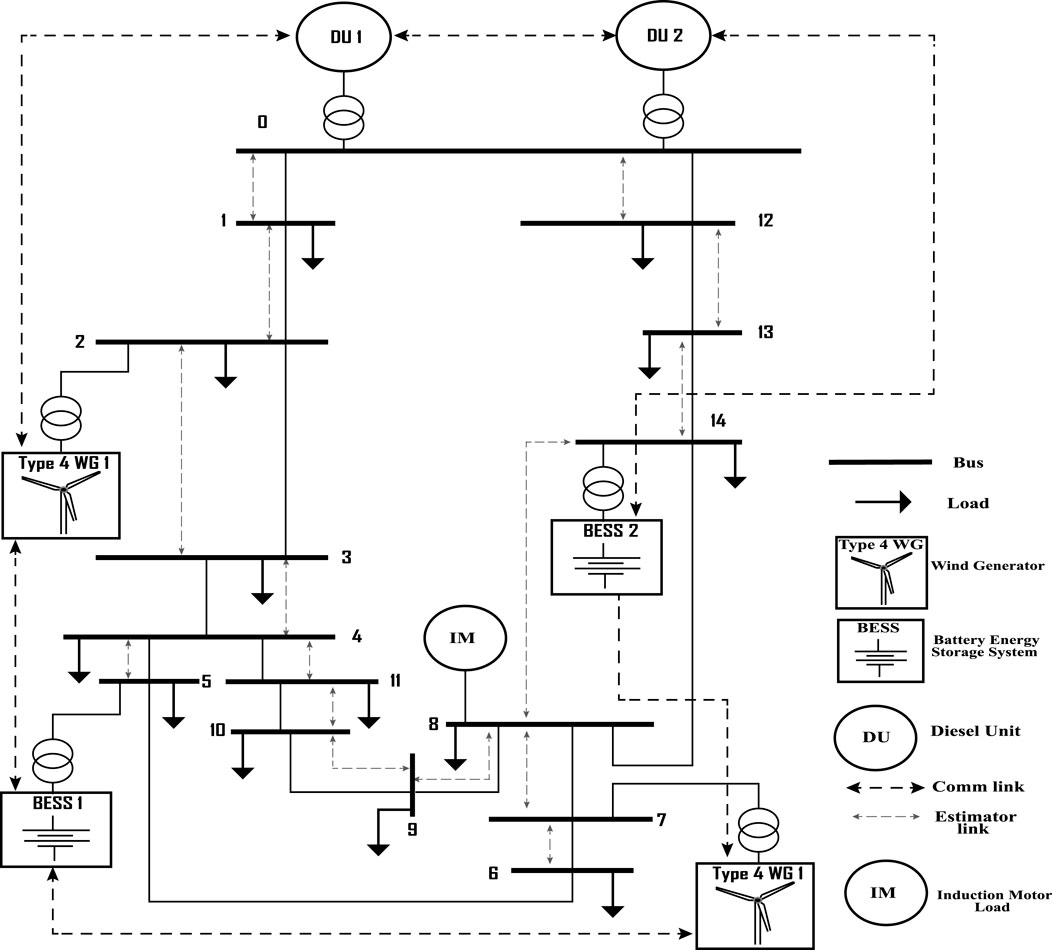
Figure 3. CIGRE benchmark microgrid with distributed communication network: modified test system. (Reprinted/adapted with permission from Alghamdi and Cañizares (2021). © 2021 IEEE).
The microgrid system had a total load of approximately 9 MVA, which included a 2 MVA induction motor load and a mix of constant impedance (60%), constant current (30%), and constant power (10%) loads. The static loads were modeled as unbalanced, consistent with the original CIGRE microgrid system (Farrokhabadi et al., 2017; Farrokhabadi et al., 2016). As detailed in Section 2, the system’s dynamic models for static loads, induction motor load, and DERs were identical to those in the original CIGRE microgrid. Table 3 summarizes the system characteristics.
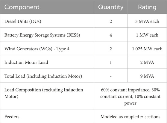
Table 3. Characteristics of the modified CIGRE benchmark Microgrid system used for simulation studies.
The microgrid’s Type 4 WGs, modeled according to Farrokhabadi et al. (2018), operated at unity power factor. Feeders were represented as coupled
The use of the modified CIGRE benchmark microgrid allows for a comprehensive evaluation of the proposed VFC scheme under realistic operating conditions and enables a fair comparison with other control strategies reported in the literature. The diverse mix of DERs, unbalanced loads, and detailed dynamic models provide a suitable platform to assess the performance of the proposed controller in terms of frequency regulation, voltage stability, power sharing, and fault-induced delayed voltage recovery (FIDVR) mitigation.
4.2 Tuning of controller parameters
A genetic algorithm (GA) optimization technique was employed to tune the proposed distributed consensus-based VFC scheme’s control parameters. These include
The optimization problem was formulated using a multi-objective function that combines the integral of the time-multiplied absolute value of the error (ITAE) for frequency deviation, voltage deviation, and reactive power sharing error, given by:
where
The genetic algorithm optimization was implemented using PSCAD’s built-in GA optimization tool. The process involved the following steps:
Multiple optimization runs with different random seeds ensured solution robustness. The final control parameters were selected from the best performing solution across all runs.
To evaluate the controller’s performance and determine the optimal parameter values, the microgrid system was subjected to various disturbances, such as load changes, DER outages, fault-induced delayed voltage recovery (FIDVR) events, and communication delays. The GA minimized the objective function Equation 33 until the optimization converged, yielding the tuned controller parameters.
The tuned values of the key control parameters are presented in Table 4. These values were obtained by considering the specific characteristics of the microgrid system, the desired performance criteria, and the results from the GA optimization.
The tuned values of the control parameters ensure that the proposed VFC scheme provides effective frequency regulation, voltage stability, FIDVR mitigation, and accurate reactive power sharing among the DERs. The adaptive gain adjustment mechanism for the active power control loop, with
The GA optimization approach allows for a systematic and efficient tuning process, considering the complex interactions between the various control loops, the specific requirements of the microgrid system, and the additional challenges posed by communication delays and FIDVR events. The resulting tuned parameters provide a balanced trade-off between the different performance objectives, ensuring the stable and reliable operation of the microgrid under various operating conditions.
4.3 Simulation scenarios
To comprehensively evaluate the performance of the proposed distributed consensus-based VFC strategy, four simulation scenarios were designed to test the microgrid under various operating conditions and disturbances. These scenarios were chosen to demonstrate the capabilities of the proposed controller in regulating frequency, mitigating fault-induced delayed voltage recovery (FIDVR), maintaining stable operation in the presence of communication delays, and handling different fault durations.
Scenario 1: Sudden load increase during low wind power output.
In this introductory scenario, a sudden load increase is applied to the microgrid at t = 105 s, coinciding with the lowest output power from the wind generators. This scenario aims to demonstrate the effectiveness of the proposed VFC strategy in regulating the microgrid frequency and maintaining stable operation under challenging conditions. The performance of the proposed controller is compared to the base case with conventional droop control to highlight its superior frequency regulation capabilities.
Scenario 2: Three-phase fault at Bus 8 causing FIDVR.
To evaluate the proposed VFC strategy’s ability to mitigate FIDVR, a three-phase fault is applied to Bus 8 at t = 20 s. This scenario is designed to assess the impact of FIDVR on the microgrid voltage and compare the voltage recovery performance of the proposed controller with the base case and conventional VFC strategies. By demonstrating improved voltage recovery, this scenario showcases the effectiveness of the proposed VFC strategy in enhancing the microgrid’s resilience to FIDVR events.
Scenario 3: Three-phase fault at Bus 8 with communication delays.
Building upon Scenario 2, this scenario introduces communication delays to the microgrid system while a three-phase fault is applied at Bus 8. The purpose of this scenario is to investigate the robustness of the proposed VFC strategy in the presence of communication delays, which can potentially impact the performance of distributed control schemes. By evaluating the controller’s performance under these conditions, this scenario demonstrates the resilience and practicality of the proposed VFC strategy in real-world microgrid applications.
Scenario 4: Impact of fault duration on voltage recovery.
In this scenario, the impact of fault duration on the voltage recovery time is investigated for both the proposed VFC strategy and the conventional VFC. A three-phase fault is applied at Bus 8 with varying durations, specifically 0.045s and 0.05s. The purpose of this scenario is to assess the effectiveness of the proposed VFC strategy in handling different fault durations and to compare its performance with the conventional VFC in terms of voltage recovery time and stability. By demonstrating faster voltage recovery times and improved stability under different fault durations, this scenario highlights the robustness and superiority of the proposed VFC strategy in mitigating FIDVR events and maintaining microgrid stability.
These four simulation scenarios provide a comprehensive evaluation of the proposed VFC strategy’s performance under various operating conditions, disturbances, and challenges. By assessing the controller’s effectiveness in regulating frequency, mitigating FIDVR, maintaining stable operation in the presence of communication delays, and handling different fault durations, these scenarios demonstrate the versatility, resilience, and practicality of the proposed VFC strategy in real-world microgrid applications.
4.4 Performance evaluation of the proposed VFC strategy
The performance of the proposed distributed consensus-based VFC strategy was evaluated under a challenging scenario where the microgrid experiences a sudden load increase at t = 105 s, coinciding with the lowest output power from the wind generators. Figure 4 shows the frequency response of the microgrid system under the proposed VFC strategy (blue line) compared to the base case with conventional droop control (red line).
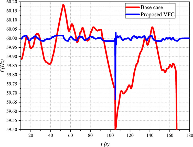
Figure 4. Frequency response of the microgrid system under the proposed VFC strategy and the base case with conventional droop control, subjected to a sudden load increase at t = 105 s.
In the base case, the microgrid frequency drops significantly, reaching a minimum of approximately 59.55 Hz, and undergoes several oscillations before slowly recovering and eventually collapses again. In contrast, the proposed VFC strategy demonstrates superior performance, with a less severe frequency drop (minimum of around 59.85 Hz), faster and smoother recovery, and fewer oscillations.
The improved frequency response under the proposed VFC strategy is attributed to the distributed consensus-based control architecture, the coordination between the VFC and active power control loops, and the optimally tuned control parameters. These results highlight the effectiveness of the proposed VFC strategy in maintaining microgrid frequency stability and ensuring smooth operation under challenging scenarios.
In the following subsections, we will further investigate the performance of the proposed VFC strategy under different simulation scenarios, including fault-induced delayed voltage recovery (FIDVR) events, and compare its performance with existing control methods reported in the literature.
Scenario 2: Three-phase fault at Bus 8 causing FIDVR.
To evaluate the performance of the proposed VFC strategy in mitigating fault-induced delayed voltage recovery (FIDVR), a three-phase fault was applied at Bus 8 at t = 20 s, lasting for 0.045 s. The voltage response of the microgrid was observed, focusing on the average microgrid voltage (Figure 5) and the voltage at the terminal of the induction motor load (Figure 6).
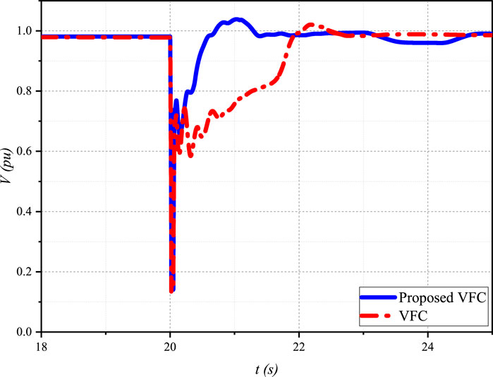
Figure 5. Average microgrid voltage during a three-phase fault at Bus 8, comparing the proposed VFC strategy with conventional VFC.
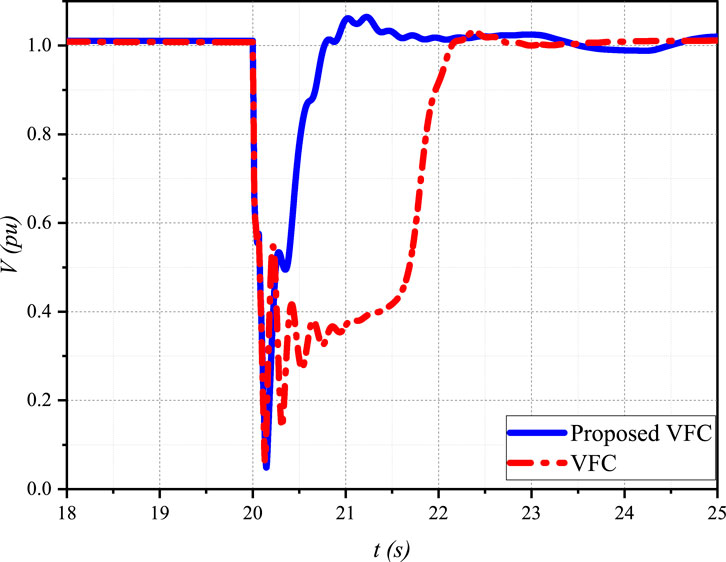
Figure 6. Induction motor terminal voltage during a three-phase fault at Bus 8, comparing the proposed VFC strategy with conventional VFC.
In the base case with conventional VFC (red line), the average microgrid voltage (Figure 5) experiences a severe drop to approximately 0.1 pu during the fault. After the fault is cleared, the voltage recovers slowly, taking more than 2 s to reach the pre-fault level. This delayed voltage recovery is primarily caused by the stalling of induction motor loads, which draw a large amount of reactive power during the post-fault period.
Similarly, the voltage at the induction motor terminal (Figure 6) drops to nearly zero during the fault and exhibits a delayed recovery in the base case. The motor voltage remains below 0.8 pu for more than 2 s after the fault is cleared, indicating a prolonged stalling condition.
In contrast, the proposed VFC strategy (blue line) demonstrates a significantly improved voltage recovery performance. The average microgrid voltage (Figure 5) drops to approximately 0.1 pu during the fault. However, after the fault is cleared, the voltage recovers much faster, reaching the pre-fault level within 1 s. This rapid voltage recovery is achieved by the proposed VFC’s ability to detect the FIDVR condition and adjust the voltage setpoints of the DERs to provide additional reactive power support.
The voltage at the induction motor terminal (Figure 6) also exhibits a faster recovery under the proposed VFC strategy. The motor voltage reaches 0.8 pu within 1 s after the fault is cleared, indicating a shorter stalling duration and improved motor performance.
Figure 7 compares the voltage recovery time of the proposed VFC strategy and the conventional VFC. The proposed VFC demonstrates a significantly faster voltage recovery, taking approximately 0.5 s, while the conventional VFC requires around 2 s to restore the voltage to its nominal value. This highlights the superior performance of the proposed VFC strategy in mitigating FIDVR and ensuring rapid voltage recovery.
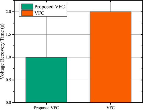
Figure 7. Comparison of voltage recovery time between the proposed VFC strategy and the conventional VFC.
The superior voltage recovery performance of the proposed VFC strategy can be attributed to several factors:
1. The modified VFC equation Equation 21, which includes a voltage error term and a switching mechanism based on the estimated global average voltage, enables the controller to prioritize voltage recovery during FIDVR events.
2. The proximity-based reactive power support prioritization ensures that DERs closer to the fault location provide more reactive power support, effectively mitigating the voltage sags caused by FIDVR.
3. The distributed voltage estimator provides an accurate representation of the microgrid voltage profile, allowing for a coordinated and targeted response to FIDVR events.
These results demonstrate the effectiveness of the proposed VFC strategy in mitigating FIDVR and ensuring a faster and more stable voltage recovery compared to conventional VFC methods. By maintaining higher voltage levels during faults and reducing the duration of induction motor stalling, the proposed VFC strategy enhances the microgrid’s resilience to disturbances and improves overall system stability.
In Scenario 2, the reactive power sharing performance of the proposed VFC strategy was evaluated during a three-phase fault at Bus 8, which caused a fault-induced delayed voltage recovery (FIDVR) event. Figure 8 shows the reactive power output of BESS 1 and BESS 3 during the post-fault period.
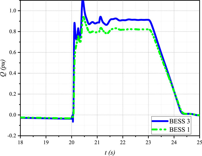
Figure 8. Reactive power output of BESS 1 and BESS 3 during the post-fault period, demonstrating the proximity-based reactive power sharing mechanism of the proposed VFC strategy.
The reactive power sharing mechanism in the proposed VFC strategy is based on the proximity of each DER to the fault location, as described in the power sharing Equation 23. After the fault is cleared, BESS 3, which is closer to the fault location at Bus 8, provides a higher reactive power output compared to BESS 1. This is in accordance with the proximity-based reactive power sharing mechanism, where DERs closer to the fault location are assigned higher reactive power support factors
The gradual reduction in reactive power output of both BESS units after the fault is cleared indicates the effectiveness of the proposed VFC strategy in mitigating the FIDVR event and restoring the microgrid voltage to its nominal value. The proximity-based reactive power sharing ensures that the DERs closer to the fault location bear a larger share of the reactive power burden, thereby minimizing the overall voltage deviations and enhancing the speed of voltage recovery.
These results demonstrate the successful implementation of the proximity-based reactive power sharing mechanism in the proposed VFC strategy, which prioritizes the contribution of DERs closer to the fault location during FIDVR events. By effectively coordinating the reactive power support provided by the DERs, the proposed VFC strategy ensures a faster and more stable voltage recovery, enhancing the microgrid’s resilience to disturbances.
Figure 9 shows the speed of the induction motor load connected to the microgrid during Scenario 2. The motor speed experiences a sudden drop due to the voltage sag caused by the three-phase fault at Bus 8. In the case of conventional VFC (red line), the motor speed drops to approximately 0.92 pu and takes a long time to recover after the fault is cleared, indicating the impact of fault-induced delayed voltage recovery (FIDVR) on the motor’s performance.
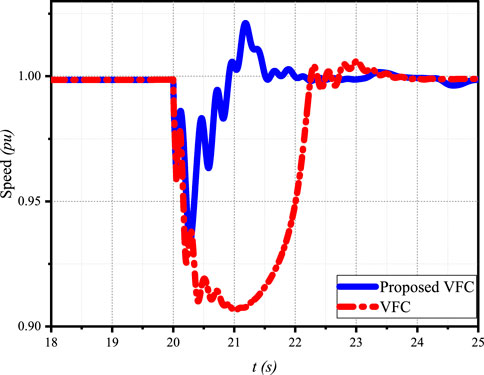
Figure 9. Induction motor speed during and after a three-phase fault at Bus 8, comparing the proposed VFC strategy with conventional VFC.
In contrast, the proposed VFC strategy (blue line) demonstrates a significantly improved motor speed response. Although the motor speed drops during the fault, it recovers much faster after the fault is cleared compared to the conventional VFC case. The faster recovery of the motor speed under the proposed VFC strategy can be attributed to the improved voltage recovery performance, as discussed in the previous sections.
The proposed VFC strategy demonstrates superior performance in restoring the system frequency and voltage to nominal values compared to the conventional VFC approach, as evident from Figures 1, 2.
Figure 10 shows that the active power output of BESS 1 and 3 using the proposed VFC strategy exhibits a more rapid and coordinated response to the fault-induced disturbance compared to BESS 1 using conventional VFC. The proposed VFC enables the BESS units to quickly inject active power into the system to support frequency recovery.
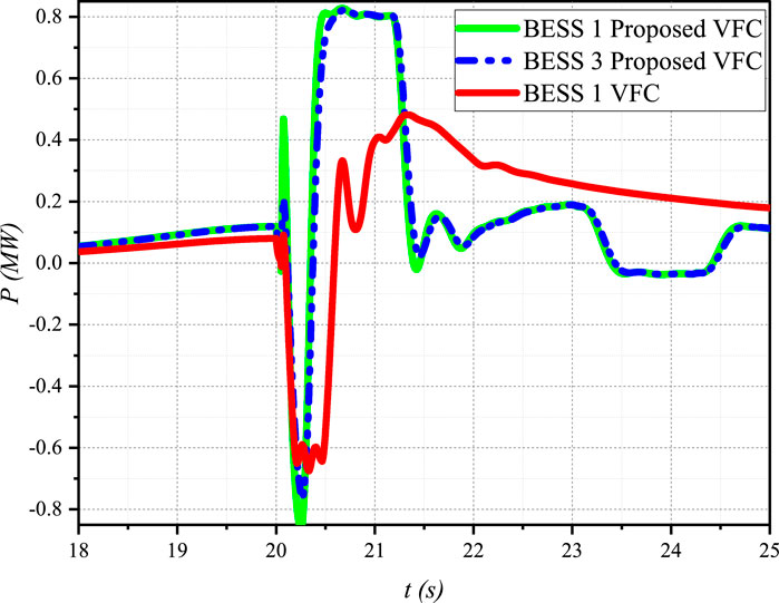
Figure 10. Active power output of BESS units under the proposed VFC and conventional VFC strategies.
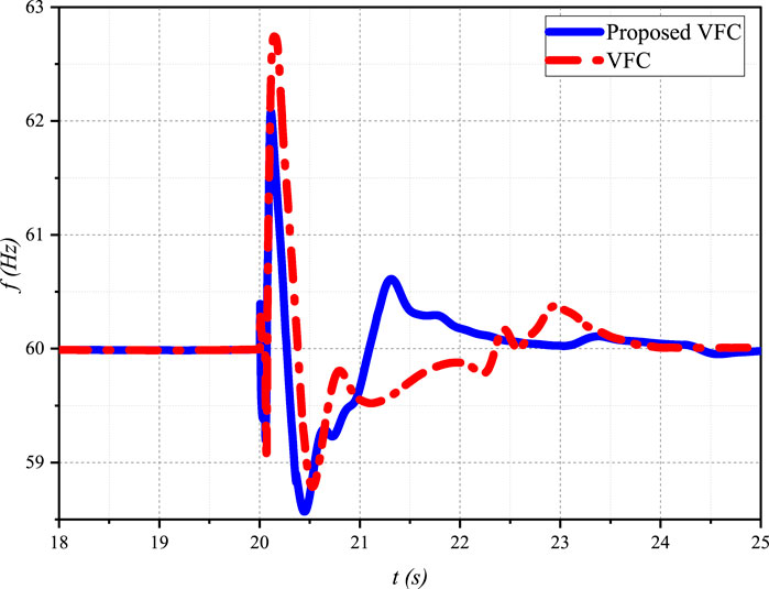
Figure 11 illustrates the system frequency response under both the proposed and conventional VFC strategies. The proposed VFC achieves a faster frequency recovery, with the frequency returning to its nominal value within approximately 2 s after the fault. In contrast, the conventional VFC exhibits a slower and more oscillatory frequency response, taking longer to stabilize.
The effectiveness of the proposed VFC strategy can be attributed to the adaptive gain adjustment mechanism implemented in the active power control loop. During the FIDVR event, the gains of the active power controller are dynamically adjusted to provide a faster and more aggressive response to frequency deviations caused by the constant power load behavior of stalled induction motor loads. This adaptive approach ensures that the active power control loop prioritizes frequency stability, enabling a more rapid and robust frequency recovery.
The coordinated action of the BESS units, facilitated by the distributed consensus control architecture, further enhances the overall system performance. The BESS units collectively contribute to frequency regulation and voltage support, leading to a more stable and resilient microgrid operation.
Scenario 3: Three-phase fault at Bus 8 with communication delays.
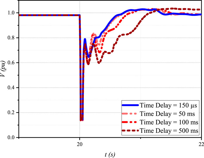
The impact of communication delays on the performance of the proposed VFC strategy was evaluated by applying a three-phase fault at Bus 8 and observing the average microgrid voltage recovery under different time delay conditions (150 µs, 50 m, 100 m, and 500 m), as shown in Figure 12.
The results demonstrate that the proposed VFC strategy can restore the average microgrid voltage to its nominal value, even in the presence of communication delays. However, the voltage recovery time increases with larger time delays. In the worst-case scenario (500 m delay), the voltage recovery is significantly slower, taking approximately 1.5 s to reach the nominal value after the fault is cleared. Despite the slower recovery, no instability is observed, highlighting the robustness of the proposed VFC strategy.
The slower voltage recovery with larger time delays is attributed to the delayed communication and coordination among the DERs. Nevertheless, the proposed VFC strategy’s adaptive gain adjustment mechanism and the coordination between the VFC and active power control loops help maintain stability and eventually restore the voltage to its nominal value.
These results demonstrate the resilience and effectiveness of the proposed VFC strategy in handling communication delays, ensuring reliable operation of the microgrid under realistic conditions where communication infrastructure may introduce latencies.
Scenario 4: Impact of fault duration on voltage recovery.
Figure 13 shows the voltage at the terminal of the induction motor (IM) load for fault durations of 0.045s and 0.05s, comparing the proposed VFC and the conventional VFC.
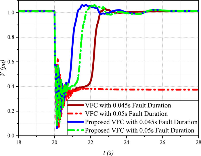
Figure 13. Induction motor load voltage recovery comparison between the proposed VFC and conventional VFC for fault durations of 0.045s and 0.05s.
The proposed VFC achieves faster voltage recovery compared to the conventional VFC for both fault durations. With a fault duration of 0.05s, the conventional VFC fails to recover the voltage, and the IM load stalls, while the proposed VFC restores the voltage within approximately 1 s after the fault is cleared. For a fault duration of 0.045s, the proposed VFC exhibits a faster voltage recovery than the conventional VFC. Longer fault durations lead to slower voltage recovery for both control strategies.
Figure 14 compares the voltage recovery time of the proposed VFC strategy and the conventional VFC for different fault durations. The proposed VFC consistently achieves faster voltage recovery times compared to the conventional VFC, with recovery times of approximately 1.1 s and 1.3 s for fault durations of 0.045s and 0.05s, respectively. In contrast, the conventional VFC exhibits significantly slower recovery times of around 2.5 s for a fault duration of 0.045s and fails to recover the voltage for a fault duration of 0.05s, indicating potential voltage instability.
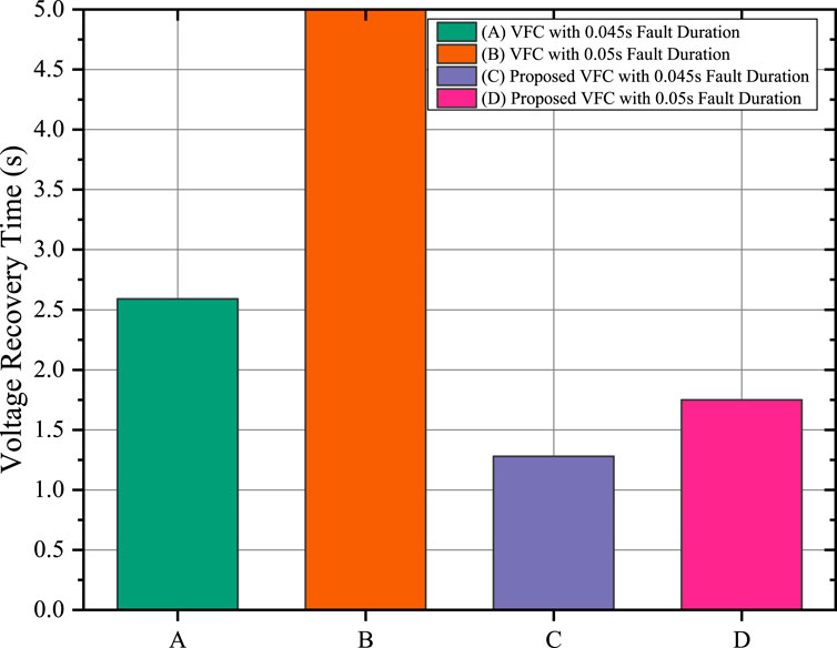
Figure 14. Comparison of voltage recovery times for the proposed VFC and conventional VFC under different fault durations.
4.5 Summary of performance improvements
To provide a consolidated overview of the improvements achieved by the proposed VFC strategy, Table 5 presents a comparison of key performance metrics between the proposed VFC and conventional methods.
As observed from Table 5, the proposed VFC strategy reduced the voltage recovery time after a 0.045s fault from 2.5 s to 1.1 s, representing a 56% improvement. Similarly, under sudden load increases, the frequency deviation was limited to
5 Conclusion
This paper presents a novel distributed consensus-based voltage and frequency control (VFC) strategy for isolated microgrids with distributed energy resources (DERs) to regulate frequency and voltage while effectively mitigating fault-induced delayed voltage recovery (FIDVR) events caused by induction motor load stalling.
The proposed VFC strategy incorporates several innovative features, including a voltage control loop with proximity-based reactive power sharing, an adaptive gain adjustment mechanism in the active power control loop, and a distributed voltage estimator. These components work in concert to ensure effective coordination among DERs during normal operation and FIDVR events.
The inclusion of an adaptive gain adjustment mechanism in the active power control loop allows the controller to dynamically adapt to varying disturbance conditions by adjusting the control gains based on the system’s voltage level. During FIDVR events, when the voltage is significantly depressed, the adaptive mechanism increases the control gains, enabling a faster and more aggressive response to frequency deviations caused by the constant power behavior of stalled induction motors. This enhances system robustness by ensuring faster frequency stabilization and improved coordination between voltage and frequency control during disturbances.
Comprehensive simulation results demonstrate the superior performance of the proposed VFC strategy compared to conventional methods. Key achievements include:
These findings confirm that the proposed VFC strategy significantly enhances microgrid performance in terms of voltage recovery, frequency stability, reactive power sharing, and robustness to communication delays and fault conditions.
The implications of this work for future research and practical applications in microgrid control are significant. This study contributes to the development of advanced distributed control strategies capable of addressing complex phenomena in microgrids with high penetration of induction motor loads. The proposed VFC strategy offers a practical solution for improving the resilience and stability of isolated microgrids, particularly in scenarios where network conditions may be less than ideal.
In the broader context of renewable energy integration, this work advances the development of more reliable and stable microgrid systems, which is crucial for increasing the penetration of distributed energy resources in power systems. Future work could focus on experimental validation and real-world implementation to provide further insights into practical challenges and opportunities.
In conclusion, the distributed consensus-based VFC strategy presented in this paper represents a significant advancement in microgrid control techniques. By effectively addressing the challenges of frequency regulation, voltage stability, and FIDVR mitigation through mechanisms such as adaptive gain adjustment in the active power control loop, this work contributes to the ongoing development of more resilient, efficient, and sustainable power systems.
Data availability statement
The original contributions presented in this study are included in the article. Further inquiries can be directed to the corresponding author.
Author contributions
BA: Conceptualization, Data curation, Formal Analysis, Funding acquisition, Investigation, Methodology, Project administration, Resources, Software, Supervision, Validation, Visualization, Writing–original draft, Writing–review and editing.
Funding
The author declares that financial support was received for the research, authorship, and/or publication of this article. This Project was funded by the Deanship of Scientific Research (DSR) at King Abdulaziz University, Jeddah, under grant no. (GPIP: 149-135-2024). The author, therefore, acknowledge with thanks DSR for technical and financial support.
Acknowledgments
The author used OpenAI’s GPT-4o model (accessed via the OpenAI API) and Grammarly for language editing and proofreading. These tools were employed solely to improve clarity and grammar; the author takes full responsibility for all final content and conclusions.
Conflict of interest
The author declares that the research was conducted in the absence of any commercial or financial relationships that could be construed as a potential conflict of interest.
Publisher’s note
All claims expressed in this article are solely those of the authors and do not necessarily represent those of their affiliated organizations, or those of the publisher, the editors and the reviewers. Any product that may be evaluated in this article, or claim that may be made by its manufacturer, is not guaranteed or endorsed by the publisher.
References
Alghamdi, B. (2022a). Distributed voltage frequency control of isolated microgrids. IEEE Access 10, 134799–134810. doi:10.1109/ACCESS.2022.3232725
Alghamdi, B. (2022b). Fuzzy logic–based decentralized voltage–frequency control and inertia control of a vsg-based isolated microgrid system. Energies 15, 8401. doi:10.3390/en15228401
Alghamdi, B., and Cañizares, C. A. (2021). Frequency regulation in isolated microgrids through optimal droop gain and voltage control. IEEE Trans. Smart Grid 12, 988–998. doi:10.1109/TSG.2020.3028472
Benali, A., Khiat, M., Allaoui, T., and Denai, M. (2018). Power quality improvement and low voltage ride through capability in hybrid wind-pv farms grid-connected using dynamic voltage restorer. IEEE Access 6, 68634–68648. doi:10.1109/ACCESS.2018.2878493
Bidram, A. (2017). Cooperative synchronization in distributed microgrid control. Cham, Switzerland: Springer.
Choi, J., Habibi, S. I., and Bidram, A. (2022). Distributed finite-time event-triggered frequency and voltage control of ac microgrids. IEEE Trans. Power Syst. 37, 1979–1994. doi:10.1109/TPWRS.2021.3110263
Farrokhabadi, M., Cañizares, C., and Bhattacharya, K. (2016). “A voltage-based frequency controller for inverter-based systems in microgrids,” in 2016 IEEE power and energy society general meeting (PESGM), 1–5. doi:10.1109/PESGM.2016.7741281
Farrokhabadi, M., Cañizares, C. A., and Bhattacharya, K. (2017). Frequency control in isolated/islanded microgrids through voltage regulation. IEEE Trans. Smart Grid 8, 1185–1194. doi:10.1109/TSG.2015.2479576
Farrokhabadi, M., König, S., Cañizares, C. A., Bhattacharya, K., and Leibfried, T. (2018). Battery energy storage system models for microgrid stability analysis and dynamic simulation. IEEE Trans. Power Syst. 33, 2301–2312. doi:10.1109/TPWRS.2017.2740163
Farrokhabadi, M., Simpson-Porco, J. W., and Cañizares, C. A. (2021). “Optimal design of voltage-frequency controllers for microgrids,” in 2021 IEEE Madrid PowerTech, 1–6. doi:10.1109/PowerTech46648.2021.9495073
Gole, A. M., Filizadeh, S., Menzies, R. W., and Wilson, P. L. (2005). Optimization-enabled electromagnetic transient simulation. IEEE Trans. Power Deliv. 20, 512–518. doi:10.1109/TPWRD.2004.835385
Gu, W., Tan, Y., Chen, H., and Zhang, X. (2022). Transient stability analysis of induction motor-load system considering the effect of voltage sag. IEEE Access 10, 4120–4130. doi:10.1109/ACCESS.2022.3140012
Hossain, M. A., Pota, H. R., Hossain, M. J., and Blaabjerg, F. (2019). Evolution of microgrids with converter-interfaced generations: challenges and opportunities. Int. J. Electr. Power Energy Syst. 109, 160–186. doi:10.1016/j.ijepes.2019.01.038
Huang, S., Xiong, L., Zhou, Y., Liu, J., Jia, Q., Li, P., et al. (2023). Distributed predefined-time secondary frequency and average voltage control for islanded ac microgrids. IEEE Trans. Power Syst. 38, 4191–4205. doi:10.1109/TPWRS.2022.3209981
Kansal, P., and Bose, A. (2012). Bandwidth and latency requirements for smart transmission grid applications. IEEE Trans. Smart Grid 3, 1344–1352. doi:10.1109/TSG.2012.2197229
Krause, P. C., Wasynczuk, O., Sudhoff, S. D., and Pekarek, S. D. (2013). Analysis of electric machinery and drive systems. 3 edn. Wiley-IEEE Press.
Ling, C., Hu, J., Liu, J., Yu, T., and Huang, L. (2021). Transient stability analysis of induction motor-load system considering stator flux dynamics. IEEE Trans. Power Syst. 36, 4502–4511. doi:10.1109/TPWRS.2021.3057536
Mohiuddin, S. M., and Qi, J. (2022). Optimal distributed control of ac microgrids with coordinated voltage regulation and reactive power sharing. IEEE Trans. Smart Grid 13, 1789–1800. doi:10.1109/TSG.2022.3147446
Nasirian, V., Shafiee, Q., Guerrero, J. M., Lewis, F. L., and Davoudi, A. (2016). Droop-free distributed control for ac microgrids. IEEE Trans. Power Electron. 31, 1600–1617. doi:10.1109/TPEL.2015.2414457
Nasr-Azadani, E., Cañizares, C. A., Olivares, D. E., and Bhattacharya, K. (2014). Stability analysis of unbalanced distribution systems with synchronous machine and DFIG based distributed generators. IEEE Trans. Smart Grid 5, 2326–2338. doi:10.1109/tsg.2014.2321709
Nayeripour, M., Mahboubi-Moghaddam, E., and Aghamohammadi, M. R. (2018). Dynamic state estimation based protection scheme for microgrids with induction motor loads. IEEE Trans. Smart Grid 9, 5873–5882. doi:10.1109/TSG.2017.2711022
Olivares, D. E., Mehrizi-Sani, A., Etemadi, A. H., Cañizares, C. A., Iravani, R., Kazerani, M., et al. (2014). Trends in microgrid control. IEEE Trans. Smart Grid 5, 1905–1919. doi:10.1109/TSG.2013.2295514
Paredes, L. A., Molina, M. G., and Serrano, B. R. (2023). Enhancing dynamic voltage stability in resilient microgrids using facts devices. IEEE Access 11, 66150–66176. doi:10.1109/ACCESS.2023.3291009
Park, B., and Olama, M. M. (2021). A model-free voltage control approach to mitigate motor stalling and fidvr for smart grids. IEEE Trans. Smart Grid 12, 67–78. doi:10.1109/TSG.2020.3012308
Solanki, B. V., Bhattacharya, K., and Cañizares, C. A. (2017). A sustainable energy management system for isolated microgrids. IEEE Trans. Sustain. Energy 8, 1507–1517. doi:10.1109/TSTE.2017.2692754
Solanki, B. V., Cañizares, C. A., and Bhattacharya, K. (2019). Practical energy management systems for isolated microgrids. IEEE Trans. Smart Grid 10, 4762–4775. doi:10.1109/TSG.2018.2868130
Stefopoulos and Meliopoulos (2006). “Induction motor load dynamics: impact on voltage recovery phenomena,” in 2005/2006 IEEE/PES transmission and distribution conference and exhibition, 752–759. doi:10.1109/TDC.2006.1668591
Teodorescu, R. (2011). Grid converters for photovoltaic and wind power systems. Piscataway, New Jersey Chichester, West Sussex: IEEE Wiley.
Vandoorn, T. L., Renders, B., Degroote, L., Meersman, B., and Vandevelde, L. (2011). Active load control in islanded microgrids based on the grid voltage. IEEE Trans. Smart Grid 2, 139–151. doi:10.1109/TSG.2010.2090911
Wang, W., and de León, F. (2020). Quantitative evaluation of der smart inverters for the mitigation of fidvr in distribution systems. IEEE Trans. Power Deliv. 35, 420–429. doi:10.1109/TPWRD.2019.2929547
Wound rotor induction machine (2023). Wound rotor induction machine. Available at: https://www.pscad.com/webhelp/Master_Library_Models/Machines/Wound_Rotor_Induction_Machine/Wound_Rotor_Induction_Machine.htm (Accessed February 11, 2023).
Xu, Y., Sun, H., Gu, W., Xu, Y., and Li, Z. (2019). Optimal distributed control for secondary frequency and voltage regulation in an islanded microgrid. IEEE Trans. Industrial Inf. 15, 225–235. doi:10.1109/TII.2018.2795584
Yazdani, A. (2010). Voltage-sourced converters in power systems: modeling, control, and applications. Hoboken, N.J: IEEE Press/John Wiley.
Keywords: distributed consensus control, voltage and frequency control, isolated microgrids, DERs, FIDVR, active power control, reactive power sharing
Citation: Alghamdi B (2025) Distributed consensus-based voltage and frequency control for isolated microgrids with fault-induced delayed voltage recovery mitigation. Front. Energy Res. 12:1468496. doi: 10.3389/fenrg.2024.1468496
Received: 22 July 2024; Accepted: 23 December 2024;
Published: 21 January 2025.
Edited by:
Shabana Urooj, Princess Nourah bint Abdulrahman University, Saudi ArabiaReviewed by:
Mohammad Amir, Indian Institutes of Technology (IIT), IndiaOmveer Singh, Gautam Buddha University, India
Copyright © 2025 Alghamdi. This is an open-access article distributed under the terms of the Creative Commons Attribution License (CC BY). The use, distribution or reproduction in other forums is permitted, provided the original author(s) and the copyright owner(s) are credited and that the original publication in this journal is cited, in accordance with accepted academic practice. No use, distribution or reproduction is permitted which does not comply with these terms.
*Correspondence: Baheej Alghamdi, YmFhYWxnYW1kaUBrYXUuZWR1LnNh
 Baheej Alghamdi