- 1Processes, Energy, Environment, and Electrical Systems, National Engineering School of Gabès, University of Gabès, Gabès, Tunisia
- 2Centre for Research Impact and Outcome, Chitkara University Institute of Engineering and Technology, Chitkara University, Punjab, Rajpura, India
- 3Applied Science Research Center, Applied Science Private University, Amman, Jordan
- 4Chitkara Centre for Research and Development, Chitkara University, Himachal Pradesh, Baddi, India
- 5Electrical Engineering Department, College of Engineering, King Saud University, Riyadh, Saudi Arabia
- 6Advanced High Voltage Engineering Research Centre, Cardiff University, Cardiff, United Kingdom
- 7Department of Electrical Engineering, Bayeh Institute, Amchit, Lebanon
The current work offers a detailed comparison of the advantages and disadvantages of microgrids concerning the developments of photovoltaic (PV) production installed near the shore and those installed offshore. As demand for renewable energy increases, integrating offshore and marine photovoltaic systems offers a promising approach to increase energy production while minimizing land use. This study explores the inherent advantages of offshore photovoltaic systems, including higher energy production due to the cooling effect of water, reduced reliance on land, and the ability to tap into sustained marine solar resources. On the other hand, this paper also addresses challenges associated with these systems, such as: B. Increased installation complexity, vulnerability to harsh ocean conditions, and potential impacts on marine ecosystems. The results in this paper show good performance for both offshore and floating PV systems, except that the offshore PV system excels over the other system by 3.13% in energy production. Moreover, the difference in the annual efficiency of the two PV systems reached 0.55%. These values are considered low because both systems are installed in water, given that both systems benefit from lower temperature and solar irradiation values. Nevertheless, these two systems equally present their own unique challenges including, but not limited to, operational and maintenance cost increase, effect on marine ecology and the technical hindrances on installation and grid interconnectivity. The aim of this review is to disentangle the achievements made regarding the current state of the art in floating photovoltaic technologies. When dealing with performance metrics, two solutions are examined in order to demonstrate the feasibility of providing the energy needs in an ecological way.
1 Introduction
The growing importance of renewable energies and the role of solar photovoltaics are crucial topics in the current context of the global energy transition. Renewable energies are clean, abundant and increasingly competitive energy sources. Among the different options for renewable energy, solar photovoltaic (PV) stands out as one of the most promising and has a high potential (Fang et al., 2018; Masenge and Mwasilu, 2020; Wu et al., 2019). This technology allows the direct conversion of solar energy into electricity by solar cells without emitting pollutants or greenhouse gases. Its clean and sustainable nature offers a promising alternative solution for combating climate change and preserving the environment (Fathy et al., 2019). In addition, the sun, an abundant source of energy accessible to all parts of the world, ensures increased energy security and independence from decreasing fossil fuel resources. In addition to this, there are many economic benefits: continuous cost reduction, modularity allowing adaptation to different energy needs and job creation in various sectors (Maka and Alabid, 2022). According to 2, in 2023, solar energy becomes the largest source of renewable energy, reaching 1,418 GW.
Photovoltaic systems are mainly classified into ground-based photovoltaic systems, roof-based photovoltaic systems, and water-based photovoltaic systems. Ground-based photovoltaic systems require a large land area. In contrast, the power generation capacity of photovoltaic systems installed on the roofs of buildings is relatively low (Liu et al., 2018). However, due to limited land resources, these land-based solar solutions cannot meet the power demand. Given that oceans cover 71% of the planet’s surface, this has been proved to be a favorable place for wind energy power plants and especially offshore and photovoltaic farms. There is rising demand from the industries with respect to expanding PV to the oceans as there is a limitless space, less dust, lighter, and cooler temperature for the PV systems. The desire for offshore photovoltaic plants will always be there regardless of the fact that at present the technological and cost challenges towards the establishment of the systems in the harsh marine environment remain the greatest.
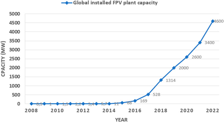
Therefore, water-based photovoltaic systems, including fixed and floating photovoltaic (FPV) systems, are gradually becoming a promising solution to help meet energy needs. Fixed photovoltaic (PV) systems utilize pile foundations to anchor themselves to the seabed (Wang and Lund, 2022). However, the economic advantages of these bottom-mounted setups diminish as water depth increases, primarily due to significantly higher costs associated with piling. In contrast, floating PV systems are designed to rest on the surface of the water and are secured in place through mooring techniques. This concept of floating photovoltaic system gained popularity in the early 2000s, with the first large-scale projects in countries such as Japan and South Korea. Since then, technology has evolved rapidly, driven by advances in floating platform design, solar panel efficiency, and system integration. FSPV systems have attracted increasing attention in recent years, attributed to their many advantages over terrestrial systems (Shyam and Kanakasabapathy, 2022). FSPV systems were first developed between 2000 and 2010, with the first small system built in Japan in 2007 and the first commercial system in California in 2008 (Farrar et al., 2022). In early 2013, Japan and South Korea witnessed the emergence of floating megawatt solar photovoltaic installations. Subsequently, the number of installations increased substantially, from a few megawatts-pics (MWc) to more than 1,300 MWc at the end of 2018. Global floating photovoltaic solar system installations exceeded 3 GW of installed capacity in 2021, with 688 MW added in 2020 alone (Figure 1) (Ramasamy and Margolis, 2021). The majority of these facilities are located in East and Southeast Asia, where 85% of global capacity is deployed. Japan and China are the leaders in this area, with approximately 200 projects and 1.3 GW of installed capacity in China, respectively. The collective FSPV capacity is expected to reach 13 GWc by 2025, a sign of a substantial increase in the global installation of FSPV systems.
Floating solar technology has been successfully implemented in several projects around the world, demonstrating its effectiveness and potential to contribute to the global energy transition. Table 1 presents the notable achievements of the floating PV industry, including their respective locations and capabilities.
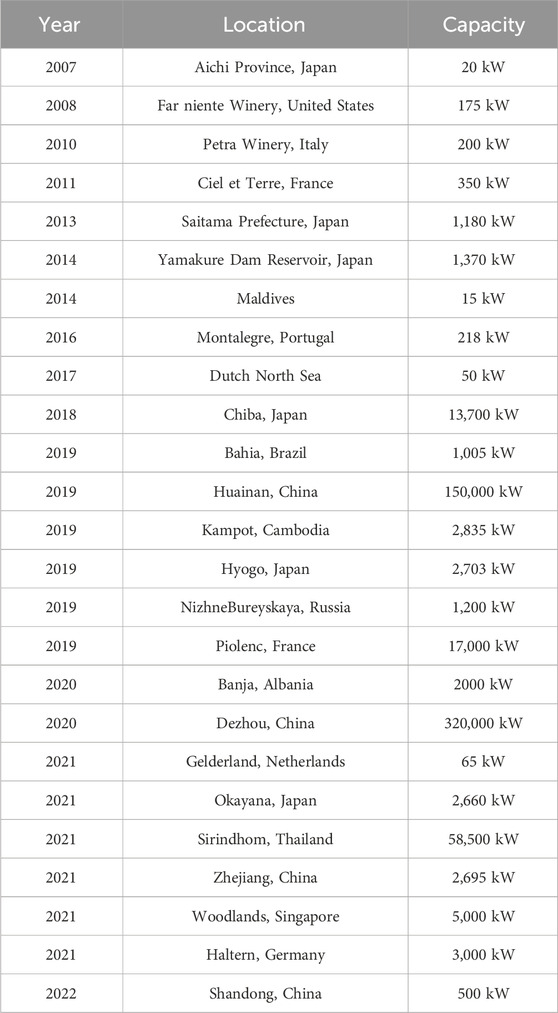
Table 1. Locations of significant floating solar photovoltaic (FPV) power plants worldwide and their capacity.
This article aims to provide a comparison between oceanic photovoltaic production systems installed in coastal environments (mainly in freshwater) and those installed in offshore environments (mainly in marine environments). In the context of microgrids, by analyzing their advantages such as energy efficiency and space utilization, as well as their limitations, including environmental impacts. The chosen model for our system is a direct current microgrid, consisting of a floating photovoltaic solar panel and a storage battery. The MATLAB/Simulink platform is used in this article to simulate the proposed system. The rest of this document is structured as follows: Section 2 provides an overview of microgrids, followed by mentions of a detailed study on floating photovoltaic systems in Section 3. Next, a model of the proposed microgrids is presented in Section 4. Section 5 presents the simulation results illustrating the different operating modes of the system developed under various conditions. Finally, Section 6 presents concluding remarks.
2 Microgrids (MGs)
A microgrid is a localized power distribution system that operates autonomously or in a mode connected to the main power grid (Ahmed et al., 2020). It is capable of generating, storing, and managing electrical energy independently. This concept is particularly suitable for remote communities, industrial facilities, hospitals, universities, or residential areas (Shahgholian, 2021) (Figure 2). The benefits of microgrids are manifold. Firstly, they increase resilience against power outages by allowing for continuous electricity supply even in the event of a failure in the main grid. This ability to operate autonomously can be crucial in remote regions or emergency situations, such as natural disasters.
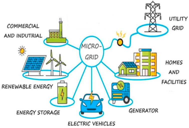
Figure 2. An example of microgrid structure. Microgrids can be classified into different categories based on various factors (Seane et al., 2022). Here are some common classifications of microgrids.
Furthermore, micro-grids promote the integration of renewable energies by enabling a more efficient and distributed use of these energy sources. This reduces dependence on fossil fuels and mitigates greenhouse gas emissions, which are essential to combating climate change. In addition, microgrids improve energy efficiency by optimizing local power generation, distribution, and consumption. By minimizing energy losses associated with long-distance transport, they allow for a more sensible use of available resources and thus contribute to a more sustainable use of energy resources. In addition, microgrids can foster local economic development by creating employment opportunities in renewable energy industries and stimulating technological innovation in the field of energy management.
2.1 Based on power energy
2.1.1 Direct current (DC) MG
Within a Direct Current (DC) microgrid, power harnessed from renewable sources undergoes direct conversion into DC electricity through power electronics. This DC electricity is subsequently distributed to the nearby energy consumers within the microgrid. Any surplus power can either be stored in batteries or converted into alternating current for potential export (Abbasi et al., 2023; Al-Ismail, 2021). A DC microgrid is a high-efficiency system that does not require any power conversion research. As a result, DC microgrids are more cost-effective than AC grids because the majority of the energy sources are DC output sources such as PV panels, batteries, and fuel cells. Similarly, the majority of the loads have direct DC input.
2.1.2 Alternating current (AC) MG
AC microgrids utilize an AC bus system to interconnect their diverse energy sources and loads. Generally, AC microgrids incorporate distributed generation sources, including renewables and traditional engine-based generators, all linked through the AC bus system. They often incorporate an energy storage medium, such as a Battery Energy Storage System (BESS). It is worth noting that some renewable sources like solar photovoltaic panels and wind turbines generate DC power, which can be converted into AC using power electronic-based converters (Chopra et al., 2022; Mohammed et al., 2019). A significant benefit of AC microgrids lies in their harmony with the pre-existing AC infrastructure. As the majority of household and commercial equipment relies on AC electricity, AC microgrids can effortlessly blend with the current electrical network, eliminating the necessity for extra conversion processes.
2.1.3 Hybrid MG
Hybrid microgrids are the combined use of AC and DC microgrids. Therefore, they have the advantages of both microgrids, such as higher reliability, efficiency, and economical operation. Hybrid AC/DC microgrids help integrate AC- and DC-based distributed energy resources, energy storage systems, and loads directly into existing distribution systems (Dagar et al., 2021). The purpose of building a hybrid microgrid is to minimize conversion levels, reduce interface equipment, increase reliability, and reduce energy costs, thereby increasing the overall efficiency of the network (Ortiz et al., 2019).
2.2 Based on operation mode
2.2.1 Stand-alone MG
An autonomous microgrid is a type of microgrid that operates independently and is disconnected from the main utility grid, essentially forming an “energy island.” It can generate, store, and distribute its own electricity without relying on external power sources. Islanded microgrids are designed to provide autonomous and self-sustaining power supply to a specific area, community, or facility (Raya-Armenta et al., 2021).
2.2.2 Grid connected MG
A grid-connected microgrid is a type of microgrid that remains interconnected with the main utility grid while also having the ability to operate autonomously or interact with the grid as needed. These microgrids are designed to offer flexibility and are typically used for various purposes, including enhancing grid reliability, improving energy efficiency, and integrating renewable energy sources (Dagar et al., 2021).
2.3 Based on energy source
2.3.1 Renewable energy source
These microgrids rely primarily on renewable energy sources such as solar photovoltaic systems, wind turbines, hydroelectric power, or biomass. They aim to reduce reliance on fossil fuels and promote clean energy generation.
2.3.2 Hybrid energy source
Hybrid microgrids combine multiple energy sources, including renewable sources and conventional sources like diesel generators or natural gas turbines. The combination of different energy sources provides flexibility, reliability, and the ability to meet varying energy demands.
3 FSPV system
Floating solar photovoltaic systems are installations that consist of placing solar panels on water planes, such as artificial lakes, water tanks, ponds, or water retentions above hydroelectric dams (Jin et al., 2023). FSPVs are an interesting option for regions with limited availability of large areas of land or for areas wishing to preserve their land for agriculture or nature conservation (Nguyen et al., 2023). Their development is part of an innovative and environmentally friendly renewable energy production approach. FSPVs work in the same way as terrestrial solar installations. Photovoltaic panels convert solar energy to direct electricity (DC). DC electricity is then converted to AC by an inverter and injected into the power grid. FSPVs can be fixed to the water surface or anchored to the bottom of the water plane. Floating structures are generally made of lightweight and corrosion-resistant materials, such as concrete, plastic, or steel. The photovoltaic panels are mounted on frames that keep them above the water surface and protect them from waves and wind. When it comes to cooling, the temperature of PV panels in FPV systems is lower compared to ground-mounted PV systems (Lindholm et al., 2021).
3.1 Components of the FSPV system
The FSPV uses a number of interconnected components to collect solar energy from panels attached to the surface of floating structures. Depending on the design and technology used, the specific components may vary; however, basic parts typically include.
3.1.1 Floating structure (potoons)
These are structures or platforms that support and float solar panels (Gorjian et al., 2021). The support structure design for FPV systems is essential and must meet criteria related to strength, stability, buoyancy, and serviceability (Dai et al., 2020). At present, high-density polyethylene (HDPE) is the predominant material used for floating structures in FPVs (Boersma et al., 2019), which includes HDPE floating pontoons, floating pipes, and platforms (Kumar et al., 2021). Connectors are anticipated to be particularly vulnerable components, especially when FPV systems are deployed in ocean environments. The persistent action of waves can cause connector fatigue and may even result in the overturning of pontoons. Consequently, enhancements are necessary for ocean applications, such as incorporating wave protection and dissipation devices around the floating structures.
Fiber-reinforced polymer (FRP) finds extensive application in FPV systems as well. In comparison to the FPV system constructed from FRP has been effectively designed, produced, and installed at Buksin Bay in Tongyeong-si, Gyeongsangnam-do, Korea (Kim et al., 2014). It offers a lighter weight along with enhanced mechanical properties and resistance to corrosion compared to traditional structural materials.
Steel and aluminum are also commonly utilized materials for floating structures (Chen et al., 2024). Finite element analysis software was employed to perform modal analysis, structural stress analysis, and deformation analysis of steel and aluminum FPV systems under various working conditions. Long-term engineering experience has led to a consensus in the field that materials made from steel and aluminum are dependable for use in FPV systems. A significant issue associated with the marine application of these materials is corrosion, which necessitates the use of anti-fouling coatings. Furthermore, the levelized cost of energy (LCOE) for this solution may currently be prohibitively high.
3.1.2 PV module
The main components of the system are solar panels. They are composed of many solar cells that convert light into energy. Different types of cells can be used in the manufacture of this module, namely, mono/multi-crystalline silicon (m-Si, p-Si), amorphous silicon (a-Si) (Kumar et al., 2020), dye-sensitized solar cells (DSCs) (Bella et al., 2016), intrinsic heterogeneous thin layers (HITs) or thin cadmium tellurate (CdTe) layers (Kumar & Kumar, 2019; Leitão et al., 2020). Floating solar panels are designed to be floating and are often manufactured with water and corrosion resistant materials (Oliveira-Pinto and Stokkermans, 2020).
3.1.3 Anchoring and mooring system
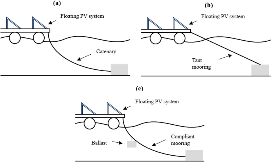
The entire array of FPV is secured against environmental forces by the mooring system, which guarantees both stability and safety (Jubayer and Hangan, 2016). For the design of FPV mooring systems in freshwater, DNV offers guidelines and suggestions (DNV GL, 2021). The mooring system can be classified into three types: catenary, compliant, and taut (Figure 3). Catenary mooring uses the weight of the mooring lines to provide a restoring force, and the pretension in the lines is crucial to limit the platform’s movement. Compliant mooring can reduce the mooring radius by connecting the lines to a buoy or sinker. Taut mooring provides a stronger restoring force than catenary mooring, using shorter lines in the same water depth, but it is more complex to install and maintain. However, taut mooring becomes more cost-effective for deep and ultra-deep water compared to the heavy catenary mooring lines. Typically, mooring lines consist of chains, wire cables, and synthetic ropes (which are more expensive) (Harris et al., 2004). Chain mooring lines are suitable for catenary mooring because their weight helps keep the mooring lines in contact with the seafloor. Additionally, wire ropes are typically selected based on their resistance to bending and fatigue, which is crucial for marine applications due to the constant loading from the ocean. Synthetic ropes exhibit more complex nonlinear effects compared to chains and wire ropes.
Freshwater plants typically use dead weights or spiral anchors to secure their mooring lines. While there is no specific research on anchoring systems for offshore floating solar panels, common marine anchoring methods may be employed, such as dead weights, dragging anchors, buried anchors, or suction-based foundations. Additionally, the stability of the seabed around the foundation should be evaluated to determine if scour protection is necessary.
3.1.4 Under water cables
Cables are employed to link the power plant’s generated electricity either to the grid or for storage in batteries. It is crucial to use waterproof and heat-resistant cables and connectors to prevent leakage and reduce the risk of electrical hazards. These cables can be extended underwater or above floaters (Cazzaniga, 2020), but they can also be used as floating cables (Where Sun Meets Water, 2019).
3.1.5 Inverters
In order to convert the direct current (DC) produced by the solar modules into alternating current (AC), the inverters play a crucial role. This alternating current can then either be directed into the grid or directly used in homes. Additionally, the inverters are responsible for regulating the electricity output, ensuring that it is distributed efficiently to either the grid or households (Ahmed et al., 2023). Plant developers have the option to use either a central or multiple-string inverter, depending on the distance from the edge to the FPV platform (Kumar et al., 2021).
3.2 Classification of the FSPV system
3.2.1 Based on module tracking
3.2.1.1 Fixed FSPV system
A bonding system attaches these fixed photovoltaic modules to floaters at an optimal angle. The advantage of this category of photovoltaic system over the floating type is the financial economy because it requires fewer mechanical structures and the design process is relatively simple (Cazzaniga et al., 2018; Mittal et al., 2017).
3.2.1.2 FSPV system with tracking
The FSPV system with tracking includes a built-in tracking mechanism that effectively monitors the sun’s azimuth angle, resulting in a significant boost of 60%–70% in energy generation when compared to the fixed-type design (Cazzaniga et al., 2018).
3.2.2 Based on floating tool
3.2.2.1 Pontoon
Pontoons made of HDPE or MDPE are commonly utilized as a floating mechanism for the FSPV system, providing ample buoyancy to support the weight of the PV system (Claus and López, 2022).
3.2.2.2 Thin film flexible FSPV modules
Flexible thin-film FPV modules offer a unique and adaptable solution for PV systems, allowing for easy deformation to conform to water waves. These modules have been found to be 5% more efficient compared to other systems (Nagananthini et al., 2020).
3.2.2.3 Submerged FSPV modules
This particular system, known as submerged FSPV, involves immersing the PV modules in shallow water. The benefits of this system include a reduction in the operating temperature of the modules due to the cooling effect of the water, as well as a decrease in light reflection when the modules are submerged. The efficiency of the modules actually improves as the depth of the water increases, reaching a maximum at an optimal depth. Research suggests that this increase in efficiency can range from 10% to 20% (Elminshawy et al., 2022).
3.3 Benefits of the FSPV system
Floating photovoltaic (PV) systems represent an optimal solution for land use, as they are installed on bodies of water rather than on land. This addresses the issue of land scarcity, especially in densely populated areas. This approach maximizes the use of existing infrastructure without impacting other land uses, such as agriculture or urban development. In addition, the cooling effect of water on solar panels increases their efficiency and performance and offsets the overheating issues common with traditional land-based systems. The shade provided by floating solar panels can also significantly reduce water evaporation from reservoirs and water bodies, which is particularly beneficial in areas with water shortages or droughts. In addition, these systems can improve water quality by limiting direct sunlight, which can inhibit algae growth and reduce waterborne diseases, ultimately improving ecosystem health. The flexibility and scalability of floating photovoltaic systems are outstanding; they are easy to install and adapt to different water bodies, from small ponds to large reservoirs and even offshore locations. This adaptability also extends to their design and allows for individual adaptation to different environmental conditions. In addition, the potential for hybrid systems that combine floating solar panels with hydropower or wind power offers diversification in renewable energy and improves overall energy reliability.
3.4 Limits and challenges of FSPV system
Floating solar photovoltaic (FPV) systems have gained attention as an emerging megawatt-scale deployment option for solar energy generation. However, they also face a number of limitations and challenges that are important to consider.
3.4.1 Technical limitation and challenges
The durability and strength of materials can be compromised in aquatic environments, particularly those with saltwater, as corrosion can corrode metal structures and electrical components. To mitigate this, it is crucial to utilize materials that are resistant to corrosion and implement additional protective measures. For instance, systems should be engineered to withstand the forces of powerful winds, waves, and sea currents, which may lead to higher expenses in design and construction (Figure 4). When it comes to maintenance and access, floating installations pose a greater challenge and expense compared to land-based systems. The difficulty in accessing these installations adds to the complexity and cost of repairs. Additionally, the presence of algae, debris, and birds necessitates more frequent cleaning, resulting in higher operating costs. To ensure stability, installations must be securely anchored, a technically intricate and costly process, particularly when dealing with deep water or water planes that have substantial level fluctuations.
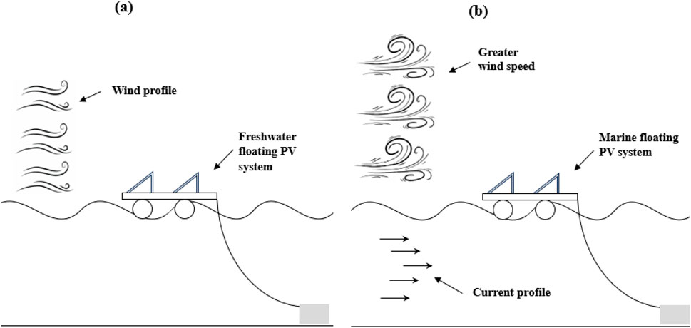
Figure 4. Environmental impacts on FPV structures in (A) freshwater environments, and (B) marine environments.
3.4.2 Environmental limitation and challenges
The presence of floating structures can have significant effects on the aquatic ecosystem. These structures have the potential to diminish the penetration of light into the water, which can disrupt the photosynthesis process of aquatic plants and disrupt the habitats of various marine organisms, including fish. Furthermore, alterations in water circulation and the creation of shade can lead to changes in water temperature and oxygen levels, ultimately impacting local ecosystems. It is also important to consider that water bodies utilized for floating photovoltaic systems may serve multiple purposes, such as irrigation, fishing, recreation, or biodiversity conservation.
3.4.3 Economic limitation and challenges
The complexity of the design, specialized materials, and anchoring systems contribute to the higher initial costs associated with floating PV systems compared to land-based installations. Additionally, as a relatively new technology, floating PVs may face technological uncertainty as industry standards have not been fully established. This lack of standards can create perceived risks for both investors and regulators.
4 Environmental loads affecting offshore floating solar PV systems
4.1 Wind speed
In offshore areas, wind loads are significantly greater than inland areas and create buoyancy and drag on FPV systems. When there is wind, installation on the water surface can cause problems with the movement and rotation of the structure, which may lead to module rupture, which is expected to have a significant impact on the power generation efficiency and service life of photovoltaic modules. It has been proven that wind can move and rotate floating structures, highlighting its significant impact on production efficiency. In the first design phase, wind-related loads on the structure (mainly considering PV panels and pontoon freeboard) can be estimated using the methodology proposed in DNVGL-RP-C205 (DNV GL, 2019).
In addition, wind resistance depends not only on the floating structure itself, but mainly on its fastening system (anchoring) (Marco and Marta, 2017). When estimating the local wind load on a PV system, the shielding effect must also be considered.
4.2 Wave
Another issue in many areas is the height of waves, which depends on wind speed and its range (Marco and Marta, 2017). Wind and waves are inextricably linked: when wind blows, it disturbs the sea surface through friction and pressure fluctuations, thus generating waves. Since large FPV systems have many connected floats, the hydrodynamic interactions between the individual floats must be considered.
The design of a floating structure and anchoring system requires initial considerations that involve studying waves alongside factors such as water currents, fetch lengths of the water surface, or tides, as relevant. This information is essential in the development of FPV systems. During this phase, gathering information efficiently from pertinent parties can greatly reduce both time and effort. Furthermore, it is crucial to thoughtfully assess how waves and wind affect floating structures and anchoring systems, as this ensures resilience to environmental influences and improves the overall robustness of the system. The materials chosen need to be able to endure stress cracking caused by wave loads.
4.3 Current
Ocean currents may not be a major issue for FPV systems installed in freshwater bodies, however, they are critical for marine applications, especially for the design of mooring and power cable systems. Ocean currents can be very complex and there are different types of currents, including ocean currents, tidal currents, wind-generated currents, and wave-induced currents, which need to be considered together. The estimation of the current loads on the structure can also be carried out using DNVGL-RP-C205. According to DNV GL (2019), the design of offshore structures must take into account currents from several perspectives: (1) significant steady movements and gradual drift of platforms; (2) lift and resistance experienced by submerged structures; (3) oscillations of structures induced by vortices; (4) interactions between currents and waves that result in alterations of wave patterns; and (5) scouring of the seabed around anchors.
5 Modelling
5.1 Modelling of the floating PV panel
A solar PV array consists of modules that are connected in series (
Where:
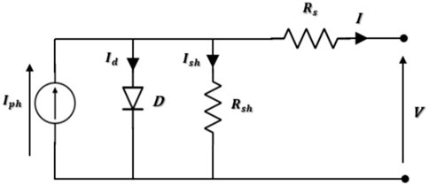
Figure 5. One diode model of a photovoltaic cell. Thus, the total current I that exits the solar PV array is given by Equations 1, 2, using the single diode model of a solar cell.
The equation of the module saturation current is given in Equation 3:
With the nominal saturation current
Equation 5, illustrates how the
In this study, Kyocera Solar KC200GT solar modules were used to build the PV system. Table 2 shows the specifications of this solar modules.
The temperature of the solar cells in a photovoltaic (PV) panel is a very important factor that affects how well the panel works. This temperature is the one at which the solar cells inside the panel are operating, and it is usually higher than the outside temperature because the panel absorbs sunlight and produces heat while turning light into electricity.
For PV system, wind speed and temperature are key factors in determining cell temperature. The cell temperature is given in Equation 6:
Where:
The equation provided for calculating the efficiency of a photovoltaic (PV) panel as a function of temperature as represented in Equation 7:
Where:
The performance ratio (PR), expressed as a percentage, de scribes the relationship between the actual and theoretical energy outputs of the PV plant, as stated in Equation 8:
Where:
5.2 Proposed MPPT method
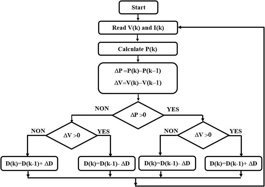
The Maximum Power Point Tracker (MPPT) function simulates the PV array and serves as a controller for the interfaced Boost converter. A number of inexpensive and simple MPPT methods, such as Perturb and Observe (P&O) and Incremental Conductance (INC) techniques, were used to maximize the PV module’s power output. Here, the P&O algorithm has been used. This algorithm is a widely accepted approach in MPPT research because it is simple and only requires voltage and current measurements of the VPV and IPV photovoltaic panels, respectively; it can detect the maximum power point even during lighting and temperature variations.
The P&O principle is based on the automatic variation of the cyclic ratio by bringing it to the optimal value in order to maximize the power delivered by the PV panel until it is placed on the MPP. Figure 6 represents the algorithm associated with a P&O-type MPPT control with a D cyclic ratio and ∆D perturbation, where the evolution of the power is analyzed after each voltage disturbance. For this type of control, two sensors (current and voltage of the GPV generator) are required to determine the power of the PV module at each moment.
5.3 Boost converter model
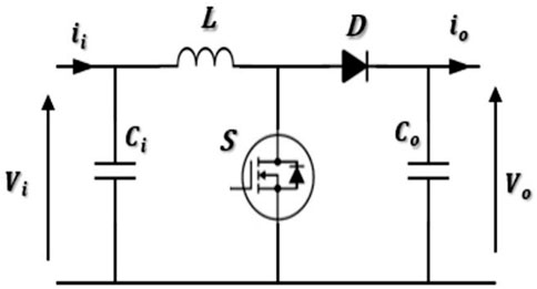
A DC-DC boost converter is a device designed to increase voltage levels from a lower to a higher range. It consists of essential components, including a switch, diode, output capacitor, and inductor. The schematic representation of a boost converter’s structure can be seen in Figure 7. This converter serves the purpose of linking the PV module to the DC bus. Its primary function is to optimize power extraction from the PV module through the implementation of an MPPT algorithm, aiming to achieve maximum power output.
5.4 Battery modelling
It is essential to possess the capability to store energy when there’s surplus power generation and utilize it during periods of low generation, as renewable energy sources within the microgrid exhibit intermittent patterns and rely on environmental conditions. In our case, it is a lithium battery.
The battery’s output voltage can be written as follows (Equation 8):
Where:
5.5 DC-DC bidirectional converter
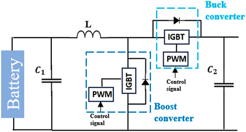
The main connection point between the BESS autonomous systems and the DC bus is facilitated by the DC-DC bidirectional converter. Its primary role is to enhance security and improve the stability of the overall performance of the microgrid. As shown in Figure 8, the bidirectional converter consists of two converters: a buck converter and a boost converter, and each converter includes a switching device (IGBT) and uses a PWM signal to activate the gate.
In the buck-boost converter, power flow is bidirectional. If there’s surplus power, a control signal triggers the converter to operate in buck mode. Conversely, when there’s a power deficit, the boost function of the bidirectional converter is activated. It elevates the voltage level, allowing the extraction of power from the battery.
6 Simulation and results discussion
This section presents simulation outcomes of the proposed microgrid to validate its effectiveness. We conduct the simulations on the MATLAB/Simulink platform because of its accuracy and user-friendly nature.
First of all, a city in Tunisia is selected as a case study site. Then, the NASA POWER service collected meteorological data such as ambient temperature, solar radiation and wind speed, at the selected location. The site is located at 33.9°N and 11.05°E. The site has an average global horizontal irradiation (GHI) of 6.8283 kWh/m2/day, average wind speed of 5.49 m/s, and average annual ambient temperature of 20.4°C. The data utilized originates from satellite imaging, providing weather information for every longitude and latitude coordinate via the NASA POWER service. We analyzed data with a monthly time resolution spanning 3 years, from January 2017 to December 2019.
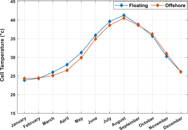
After the calculation of the cell temperature, Figure 9 shows a comparison of the calculated monthly panel cell temperatures for the two systems. These results are calculated using Equation 6. As you can see in the offshore PV system, the temperature of the panels decreases due to better cooling water. The simulation results show that the annual average panel temperature of the offshore PV system is 0.4° lower than that of the floating PV system. There is a cyclical variation in the cell temperature with summer having the highest and winter the lowest. This is connected to the extent of sunlight and the climatic conditions.
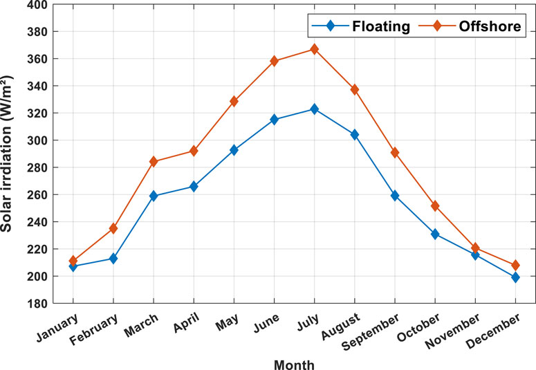
To better understand energy production, let’s discuss in the second part the difference in irradiation levels between the two locations. Figure 10 shows the average irradiation during the period of this study for both locations. For both types of systems, solar irradiation follows a classic seasonal cycle. It is minimal in winter and maximal in summer. Solar irradiation appears to be slightly higher for offshore systems. Solar irradiation appears slightly higher for offshore PV systems, by 32.48% compared to floating PV systems.
The production energy depends on the irradiance and the conversion efficiency, which in turn depends mainly on the operating temperature of the cell, which in turn is a function of the ambient and sea surface temperatures as well as the wind speed. Figure 11 show the power generation in the offshore and floating PV systems. It can be seen that the power generation of offshore PV systems is higher than that of FPV systems due to the lower temperature of the panels. Compared with FPV power stations, the power generation of offshore PV systems increases by 3.13%. Both systems demonstrate seasonal fluctuations in the generation of power. The maximum output is experienced in the summer seasons, from June to August, when the levels of solar radiation are at their peak. Conversely, the minimum output is experienced in winter months (more specifically in December, January, and February) when levels of solar radiation are at the lowest.
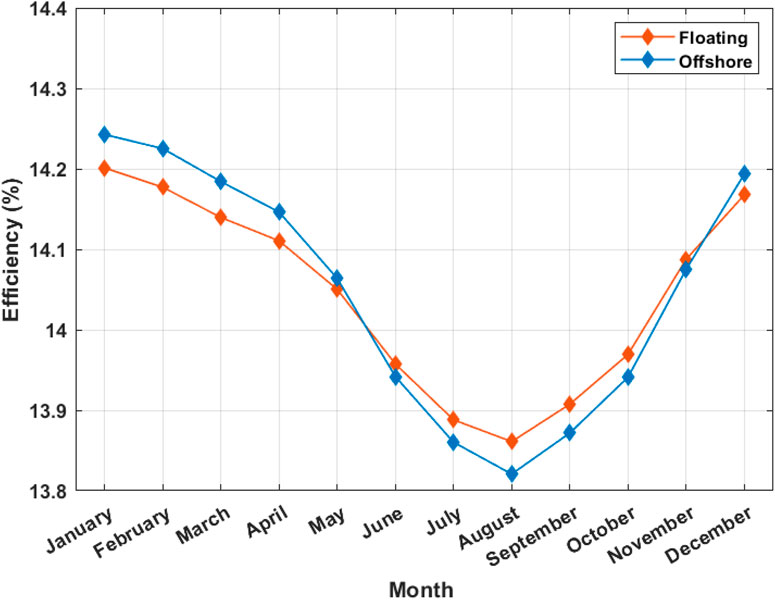
Figure 12 shows a monthly comparison of the panel efficiency for the two modes. These results are calculated using Equation 7. The annual growth rate of panel efficiency for the FPV system is 38.52%, while the panel efficiency for the GPV system is 37.24%. At all times of the year, both systems tend to have a constant level of efficiency. In the majority of the most months, it appears that offshore systems are more efficient than floating systems.
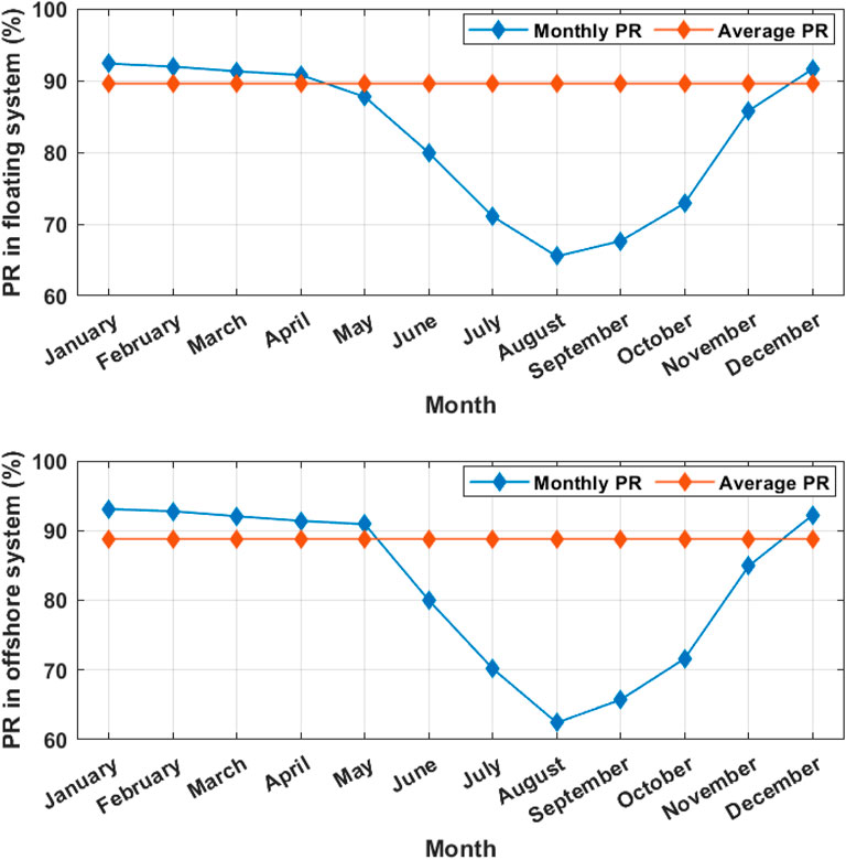
Figure 13 shows the monthly and average PR of offshore PV and FPV power plants. These results are calculated using Equation 8. The annual average PR of offshore PV and floating PV systems are 73.65% and 72.66%, respectively. It can be seen that the annual PR increase of the FPV system is about 1%.
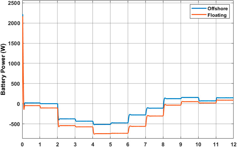
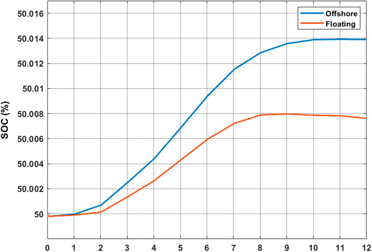
Figure 14 represent the battery power in the two systems. For the FPV system is represented by the orange color, while the power of the other type of PV is illustrated by the color blue. Figure 15 shows the state of charge of the battery, where the discharge time under the FPV system is less than for the other system. In both systems, it can be seen that the SOC in question gradually increases with time. This indicates that, slowly but surely, the batteries are charging as a result of power generated from the solar panels. The load level within the offshore system reaches a value slightly greater than that within the floating system, which may be due to several other factors, including solar radiation. Again, the increasing trend in SOC shows that the solar panels are charging the batteries efficiently. In addition, the fact that the SOC is constant means that solar power generation is enough to meet the demand. The two floating and offshore photovoltaic systems appear to be working quite well with their batteries charging efficiently.
7 Temperature and solar Irradiation effect on PV systems in water
The efficiency of solar panels and temperature are related elements that influence the overall effectiveness of a photovoltaic system. Generally, studies (Effects of Temperature, Solar Flux and Relative Humidity on the Efficient Conversion of Solar Energy to Electricity) have indicated that elevated temperatures lead to a decrease in electrical efficiency. In this manner, changes in the temperature of water can greatly influence the working efficiency of PV modules. Typically, it is observed that water tends to provide cooler ambient conditions that improve performance. Research has indicated that the temperatures of photovoltaic systems in the vicinity of water bodies are often lower than those of land-based systems. For most solar panels, each degree Celsius above the optimal operating temperature can reduce efficiency by 0.3%–0.5%. in the other side, the performance of a solar panel is directly proportional to the solar irradiation, implying that with higher levels of solar irradiance the electricity output of a PV system becomes more.
According to this paper, the offshore PV system has an average temperature of 20.4°C and 6,828.3 KWh/m2/day for the solar irradiation value. On the other hand, the offshore PV system demonstrated an average temperature of 20.44°C and 7.6079 KWh/m2/day for a solar irradiation value. The performance of solar panels is affected by temperature. In most cases, higher temperature reduces the performance of the panels. As a result, the hottest months in most cases do entail a dip in production although other aspects such as the amount of sunlight received also have an influence. Offshore sites, on average, seem to get slightly more solar irradiation. Either the water’s reduced susceptibility to haze or the panels' more favorable angular orientation could explain this.
8 Conclusion
In this article, a study is conducted to compare the oceanic photovoltaic production system and offshore in microgrids. A thorough mathematical analysis was conducted to provide accurate information on the photovoltaic system. A modeling and simulation of the proposed system were carried out using MATLAB/Simulink. In order to determine its performance, tests were conducted on offshore photovoltaic systems as well as on the floating photovoltaic system. The results reveal the superior performance of the offshore PV system in the microgrid. However, some negative points cannot be denied for this type of system.
According to this study, the results of the simulation show that the offshore PV system generates an average annual energy of 2.943 kWh, while the floating PV system produces 2.630 kWh. The offshore PV system achieved an average efficiency of 24.75%. The floating PV system, on the other hand, showed a 24.2% efficiency for photovoltaic modules. In conclusion, there is not a big difference between the performances of integrating either an offshore photovoltaic system or a floating photovoltaic system into a microgrid in our study because both systems are installed in water. Where the offshore PV system excels over the other system by just 3.13% in energy production, 0.55% in annual efficiency, and 1% in performance ratio. The high wind speed on the water reduces the temperature of solar photovoltaic cells at sea. As the temperature of the cell decreases, the efficiency of the solar photovoltaic system increases, and the production of energy produced by the photovoltaic cells increases.
Data availability statement
The original contributions presented in the study are included in the article/supplementary material, further inquiries can be directed to the corresponding author.
Author contributions
SC: Data curation, Investigation, Methodology, Writing–original draft, Writing–review and editing. FA: Methodology, Writing–original draft, Project administration, Validation, Writing–review and editing. AA: Writing–original draft, Methodology, Software. RU: Writing–original draft, Data curation, Investigation, Validation. CE-B: Writing–original draft, Conceptualization, Formal Analysis.
Funding
The author(s) declare that financial support was received for the research, authorship, and/or publication of this article. The authors declare that research work was supported by the Researchers Supporting Project number (RSP2024R258), King Saud University, Riyadh, Saudi Arabia.
Conflict of interest
The authors declare that the research was conducted in the absence of any commercial or financial relationships that could be construed as a potential conflict of interest.
Publisher’s note
All claims expressed in this article are solely those of the authors and do not necessarily represent those of their affiliated organizations, or those of the publisher, the editors and the reviewers. Any product that may be evaluated in this article, or claim that may be made by its manufacturer, is not guaranteed or endorsed by the publisher.
References
Abbasi, M., Abbasi, E., Li, L., Aguilera, R. P., Lu, D., and Wang, F. (2023). Review on the microgrid concept, structures, components, communication systems, and control methods. Energies 16 (1), 484. doi:10.3390/en16010484
Ahmed, A., Elsakka, M., Elminshawy, N., Mohamed, A., and Sundaram, S. (2023). Recent advances in floating photovoltaic systems. Chem. Rec. 23 (12), e202300229. doi:10.1002/tcr.202300229
Ahmed, M., Meegahapola, L., Vahidnia, A., and Datta, M. (2020). Stability and control aspects of microgrid architectures–a comprehensive review. IEEE Access. 8, 144730–144766. doi:10.1109/ACCESS.2020.3014977
Al-Ismail, F. S. (2021). DC microgrid planning, operation, and control: a comprehensive review. IEEE Access 9, 36154–36172. doi:10.1109/ACCESS.2021.3062840
Bella, F., Lamberti, A., Bianco, S., Tresso, E., Gerbaldi, C., and Pirri, C. F. (2016). Floating, flexible polymeric dye-sensitized solar-cell architecture: the way of near-future photovoltaics. Adv. Mater. Technol. 1 (2). doi:10.1002/admt.201600002
Cazzaniga, R. (2020). “Floating PV structures,” in Floating PV plants (Elsevier), 33–45. doi:10.1016/B978-0-12-817061-8.00004-X
Cazzaniga, R., Cicu, M., Rosa-Clot, M., Rosa-Clot, P., Tina, G. M., and Ventura, C. (2018). Floating photovoltaic plants: performance analysis and design solutions. Renew. Sustain. Energy Rev. 81, 1730–1741. doi:10.1016/j.rser.2017.05.269
Chen, B.-Q., Liu, K., and Xu, S. (2024). Recent advances in aluminum welding for marine structures. J. Mar. Sci. Eng. 12 (9), 1539. doi:10.3390/jmse12091539
Chopra, S., Vanaprasad, G. M., Tinajero, G. D. A., Bazmohammadi, N., Vasquez, J. C., and Guerrero, J. M. (2022). Power-flow-based energy management of hierarchically controlled islanded AC microgrids. Int. J. Electr. Power and Energy Syst. 141, 108140. doi:10.1016/j.ijepes.2022.108140
Claus, R., and López, M. (2022). Key issues in the design of floating photovoltaic structures for the marine environment. Renew. Sustain. Energy Rev. 164, 112502. doi:10.1016/j.rser.2022.112502
Dai, J., Zhang, C., Lim, H. V., Ang, K. K., Qian, X., Wong, J. L., et al. (2020). Design and construction of floating modular photovoltaic system for water reservoirs. Energy 191, 116549. doi:10.1016/j.energy.2019.116549
Dagar, A., Gupta, P., and Niranjan, V. (2021). Microgrid protection: a comprehensive review. Renew. Sustain. Energy Rev. 149, 111401. doi:10.1016/j.rser.2021.111401
DNV GL (2021). Available at: https://www.dnv.com/.
Elminshawy, N. A. S., Osama, A., Saif, A. M., and Tina, G. M. (2022). Thermo-electrical performance assessment of a partially submerged floating photovoltaic system. Energy 246, 123444. doi:10.1016/j.energy.2022.123444
Fang, H., Li, J., and Song, W. (2018). Sustainable site selection for photovoltaic power plant: an integrated approach based on prospect theory. Energy Convers. Manag. 174, 755–768. doi:10.1016/j.enconman.2018.08.092
Farrar, L. W., Bahaj, A. S., James, P., Anwar, A., and Amdar, N. (2022). Floating solar PV to reduce water evaporation in water stressed regions and powering water pumping: case study Jordan. Energy Convers. Manag. 260, 115598. doi:10.1016/j.enconman.2022.115598
Fathy, A., Elaziz, M. A., Sayed, E. T., Olabi, A. G., and Rezk, H. (2019). Optimal parameter identification of triple-junction photovoltaic panel based on enhanced moth search algorithm. Energy 188, 116025. doi:10.1016/j.energy.2019.116025
Gorjian, S., Sharon, H., Ebadi, H., Kant, K., Scavo, F. B., and Tina, G. M. (2021). Recent technical advancements, economics and environmental impacts of floating photovoltaic solar energy conversion systems. J. Clean. Prod. 278, 124285. doi:10.1016/j.jclepro.2020.124285
Harris, R., Johanning, L., Harris, R. E., Wolfram, J., and Frsa, M. (2006). “Mooring systems for wave energy converters: A review of design issues and choices,” in Article in Proceedings of the Institution of Mechanical Engineers Part B Journal of Engineering Manufacture. Available at: https://www.researchgate.net/publication/283549804.
Jin, Y., Hu, S., Ziegler, A. D., Gibson, L., Campbell, J. E., Xu, R., et al. (2023). Energy production and water savings from floating solar photovoltaics on global reservoirs. Nat. Sustain. 6 (7), 865–874. doi:10.1038/s41893-023-01089-6
Jubayer, C. M., and Hangan, H. (2016). A numerical approach to the investigation of wind loading on an array of ground mounted solar photovoltaic (PV) panels. J. Wind Enginee. Indus. Aerodyn. 153 (1), 60–70. doi:10.1016/j.jweia.2016.03.009
Kim, M. K., Lee, W.-Y., Kang, J.-H., Kang, J.-H., Kim, B. T., Kim, S. M., et al. (2014). 2014 clinical practice guidelines for overweight and obesity in Korea. Endocrinol. Metabolism 29 (4), 405. doi:10.3803/EnM.2014.29.4.405
Kumar, M., and Kumar, A. (2019). Performance assessment of different photovoltaic technologies for canal-top and reservoir applications in subtropical humid climate. IEEE J. Photovoltaics 9 (3), 722–732. doi:10.1109/JPHOTOV.2019.2892520
Kumar, M., Mohammed Niyaz, H., and Gupta, R. (2021). Challenges and opportunities towards the development of floating photovoltaic systems. Sol. Energy Mater. Sol. Cells 233, 111408. doi:10.1016/j.solmat.2021.111408
Kumar, N. M., Subramaniam, U., Mathew, M., Ajitha, A., and Almakhles, D. J. (2020). Exergy analysis of thin-film solar PV module in ground-mount, floating and submerged installation methods. Case Stud. Therm. Eng. 21, 100686. doi:10.1016/j.csite.2020.100686
Leitão, D., Torres, J. P. N., and Fernandes, J. F. P. (2020). Spectral irradiance influence on solar cells efficiency. Energies 13 (19), 5017. doi:10.3390/en13195017
Lindholm, D., Kjeldstad, T., Selj, J., Marstein, E. S., and Fjær, H. G. (2021). Heat loss coefficients computed for floating PV modules. Prog. Photovoltaics Res. Appl. 29 (12), 1262–1273. doi:10.1002/pip.3451
Liu, H., Krishna, V., Lun Leung, J., Reindl, T., and Zhao, L. (2018). Field experience and performance analysis of floating PV technologies in the tropics. Prog. Photovoltaics Res. Appl. 26 (12), 957–967. doi:10.1002/pip.3039
Maka, A. O. M., and Alabid, J. M. (2022). Solar energy technology and its roles in sustainable development. Clean. Energy 6 (3), 476–483. doi:10.1093/ce/zkac023
Marco, A. E. G., and Marta, M. de A. O. (2017). Some remarks about the deployment of floating PV systems in Brazil. J. Electr. Eng. 5 (1). doi:10.17265/2328-2223/2017.01.002
Masenge, I. H., and Mwasilu, F. (2020). Modeling and control of solar PV with battery energy storage for rural electrification. Tanzan. J. Eng. Technol. 39 (Issue 1), 47–58. doi:10.52339/tjet.v39i1.518
Mittal, D., Saxena, B. K., and Rao, K. V. S. (2017). Floating solar photovoltaic systems: an overview and their feasibility at Kota in Rajasthan. Int. Conf. Circuit ,Power Comput. Technol. (ICCPCT), 1–7. doi:10.1109/ICCPCT.2017.8074182
Mohammed, A., Refaat, S. S., Bayhan, S., and Abu-Rub, H. (2019). AC microgrid control and management strategies: evaluation and review. IEEE Power Electron. Mag. 6 (2), 18–31. doi:10.1109/MPEL.2019.2910292
Nagananthini, R., Nagavinothini, R., and Balamurugan, P. (2020). Floating photovoltaic thin film technology—a review (pp. 329–338). doi:10.1007/978-981-15-1616-0_32
Nguyen, N.-H., Le, B.-C., Nguyen, L.-N., and Bui, T.-T. (2023). Technical analysis of the large capacity grid-connected floating photovoltaic system on the hydropower reservoir. Energies 16 (9), 3780. doi:10.3390/en16093780
Oliveira-Pinto, S., and Stokkermans, J. (2020). Marine floating solar plants: an overview of potential, challenges and feasibility. Proc. Institution Civ. Eng. - Marit. Eng. 173 (4), 120–135. doi:10.1680/jmaen.2020.10
Ortiz, L., Orizondo, R., Águila, A., González, J. W., López, G. J., and Isaac, I. (2019). Hybrid AC/DC microgrid test system simulation: grid-connected mode. Heliyon 5 (12), e02862. doi:10.1016/j.heliyon.2019.e02862
Ramasamy, V., and Margolis, R. (2021). Floating photovoltaic system cost benchmark: Q1 2021 installations on artificial water bodies. doi:10.2172/1828287
Raya-Armenta, J. M., Bazmohammadi, N., Avina-Cervantes, J. G., Sáez, D., Vasquez, J. C., and Guerrero, J. M. (2021). Energy management system optimization in islanded microgrids: an overview and future trends. Renew. Sustain. Energy Rev. 149, 111327. doi:10.1016/j.rser.2021.111327
Seane, T. B., Samikannu, R., and Bader, T. (2022). A review of modeling and simulation tools for microgrids based on solar photovoltaics. Front. Energy Res. 10. doi:10.3389/fenrg.2022.772561
Shyam, B., and Kanakasabapathy, P. (2022). Feasibility of floating solar PV integrated pumped storage system for a grid-connected microgrid under static time of day tariff environment: a case study from India. Renew. Energy 192, 200–215. doi:10.1016/j.renene.2022.04.031
Shahgholian, G. (2021). A brief review on microgrids: Operation, applications, modeling, and control. Interna. Transac. Electri. Ener. Syst. 31 (6). doi:10.1002/2050-7038.12885
Wang, J., and Lund, P. D. (2022). Review of recent offshore photovoltaics development. Energies 15 (20), 7462. doi:10.3390/en15207462
Keywords: ocean PV system, offshore PV system, microgrid, renewable energy, comparaison, energy production, marine environments
Citation: Chayma S, Aymen F, Alkuhayli A, Ullah R and El-Bayeh CZ (2024) A comparison between the ocean and offshore photovoltaic production system into microgrids: benefits and limits. Front. Energy Res. 12:1466133. doi: 10.3389/fenrg.2024.1466133
Received: 17 July 2024; Accepted: 29 November 2024;
Published: 18 December 2024.
Edited by:
Wei Shi, Dalian University of Technology, ChinaCopyright © 2024 Chayma, Aymen, Alkuhayli, Ullah and El-Bayeh. This is an open-access article distributed under the terms of the Creative Commons Attribution License (CC BY). The use, distribution or reproduction in other forums is permitted, provided the original author(s) and the copyright owner(s) are credited and that the original publication in this journal is cited, in accordance with accepted academic practice. No use, distribution or reproduction is permitted which does not comply with these terms.
*Correspondence: Rahmat Ullah, dWxsYWhyMUBjYXJkaWZmLmFjLnVr
 Saad Chayma
 Flah Aymen
 Abdulaziz Alkuhayli
 Rahmat Ullah6*