 Langchen Huang1
 Weiling Liu
 Xinwei Wei
- 1College of Electrical and Information Engineering, Hunan University of Technology, Zhuzhou, China
- 2College of Electrical and Power Engineering, Taiyuan University of Technology, Taiyuan, China
Given the contradiction between compensating speed and compensating overshoot in traditional Proportional Integral (PI) control of Dynamic Voltage Restorer (DVR), A Feedforward compensation-active Disturbance Rejection Control (FC-ADRC) strategy based on Feedforward Compensation is proposed. ADRC control is used to improve the problem of compensating oversets existing in traditional PI control, and the voltage and current of the LC filter are introduced as the feedforward quantity to compensate the DVR controller to realize the rapid voltage compensation for the voltage dip on the user side and ensure the safety and stability of the voltage on the user side. The simulation results show that the proposed control strategy not only keeps the high dynamic response of the DVR device but also ensures the device’s adaptability to deal with uncertain disturbances.
1 Introduction
With the wide application of electronic power equipment in new industrial systems, the high-frequency harmonic pollution of power systems is increasing, and the problem of voltage sag is becoming more serious (Ma et al., 2023; Guan et al., 2023; Kang et al., 2022; Zhang et al., 2022). With the development of modern industry, the user equipment is becoming increasingly sophisticated, and the user’s requirements for power quality are increasing daily. How to ensure the safety and stability of power quality on the user side has become an urgent problem (Chen et al., 2022; Ying et al., 2023; Hong and Zhun, 2022; Liu and Tang, 2019; Gu et al., 2020) to be solved in modern power systems.
The Dynamic Voltage Restorer (DVR) generates the AC voltage with the same phase as the power grid through the power electronic device, and the compensation voltage enters the system through the power transformer in series to eliminate the influence (Deshpande et al., 2024; Jerin et al., 2017; Wang and Pei, 2022; Xin-Xin et al., 2022) of voltage sag on the user equipment. Dynamic voltage restorer (DVR) is one of the most important and effective devices for improving the user’s power quality in existing research, and it has been extensively studied by scholars at home and abroad. The main control strategy of DVR is to use the PI controller with voltage feedback so that DVR can track the voltage dip (Shukir, 2021; Appala et al., 2021; Li et al., 2018) that needs to be compensated. However, PI controller adaptability is not strong. It is easy to lead to the output voltage overshoot phenomenon, thus endangering the safety of user equipment. For the versatility of DVR in the face of different working conditions, literature (Zhang et al., 2023) proposes a composite closed-loop controller is proposed in the literature. Although this control method does not need to obtain the reference voltage value before the voltage dip, the controller needs to carry out a lot of current vector operations, and the control effect is not good when the voltage changes rapidly. Literature Li and Zhao (2022) proposes a closed-loop control idea of line voltage feedforward, but this method uses the traditional PI controller for error compensation, and overshoot still occurs when the DVR device performs voltage sag compensation.
To solve the problem of the response speed and overshoot of a dynamic voltage restorer not being balanced under the traditional PI control strategy, active disturbance rejection control technology has been introduced into the dynamic voltage restorer control field. The active disturbance rejection controller is a new control method based on disturbance estimation, which uses the extended state observer to observe the internal disturbance and external disturbance of the system and realizes the control (Ma et al., 2020; Yu et al., 2023; Wan and Yuzhen, 2022; Huiyu et al., 2020) of the nonlinear system without a precise mathematical model through the error differential feedback mechanism. Literature Ben-run et al. (2012) proposes introducing the active disturbance rejection controller into the dynamic voltage restorer as a closed-loop feedback control. Literature Kumar et al. (2021), Arya et al. (2024) aims at the problem that DVR controller’s control effect relies heavily on the parameters of proportional integral controller and its tuning method when dealing with different levels of voltage sag, and proposes to adopt optimized multi-layer neural network and fuzzy neural network control to avoid the influence of controller parameters on compensation effect. Although this method improves the control accuracy and robustness of the system, the system response speed is slow when only the active disturbance rejection controller is used to control the system. When faced with the phenomenon of power grid voltage sag, the output response speed of the dynamic voltage restorer using only the active disturbance rejection controller is difficult to track the voltage frequency after the power grid sag and the compensation voltage output of the dynamic voltage restorer will aggravate the harmonic pollution in the power grid and further endanger the safety of subsequent equipment.
Therefore, based on the existing research, this paper proposes the DVR control strategy based on feedforward active disturbance rejection and integrates the advantages of feedforward compensation control strategy and active disturbance rejection control strategy. It reduces the controller gain required by the system through feedforward compensation, improves the system response speed, and eliminates the system’s static error and overkill phenomenon by using the active disturbance rejection controller. Finally, the correctness and effectiveness of the proposed new control strategy are verified through simulation experiments.
2 Mathematical model of dynamic voltage restorer
For the theoretical feasibility verification of the control strategy proposed in this paper, this paper constructs the mathematical model of the DVR system, conducts a quantitative description and analysis of the DVR system, deeply analyzes the working principle structure and characteristics of the DVR system, and gradually builds the mathematical model of the dynamic voltage restorer based on the feedforward active disturbance rejection control strategy proposed in this paper.
In this paper, a single-phase DVR system is taken as an example to verify the feedforward active disturbance rejection control strategy. The single-phase DVR device converts the DC voltage of Udc into the required compensation voltage through SPWM modulation technology, and then the compensation voltage is cascaded into the AC bus through the isolation converter. The main circuit structure of the single-phase DVR system is shown in Figure 1. According to the state equation, output equation, and the relationship between each component of the single-phase DVR system, a dynamic voltage restorer based on a feedforward active disturbance rejection control strategy is proposed in this paper.

Figure 1. Main circuit of single-phase DVR system.
According to the topology diagram and physical information of the main circuit of the single-phase DVR system, as shown in Figure 1, the state variable equation of the single-phase DVR system can be listed as shown in Equations 1–5.
Where
To prevent the high-frequency harmonics of the compensated voltage output by the single-phase DVR device from entering the power grid, the main circuit of the single-phase DVR system connects a set of LC low-pass filters at the back end of the full-bridge inverter circuit to filter out the switching ripple in the compensated voltage.
In designing the LC filter, the filter must have as little impact as possible on the system characteristics of the single-phase DVR device. Therefore, the LC filter needs to meet the following approximate conditions within the harmonic frequency range contained in the compensated voltage:
Where s is the transformation parameter in the Laplace transform.
The full bridge circuit composed of four switching tubes constitutes the main circuit of power electronics of single-phase DVR device. By controlling the conduction of the four switching tubes, the AC voltage containing higher harmonics can be inverter output. The single-phase DVR device studied in this paper will work under bipolar PWM modulation, assuming the control quantity
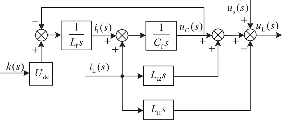
Figure 2. Single-phase DVR system control block diagram.
In the single-phase DVR device studied in this paper, the variable ratio of the isolation transformer is 1. Therefore, the voltage and current of the primary and secondary sides of the transformer are equal, that is
When the single-phase DVR control system is in the open loop control, the control quantity
Where,
Equation 6 and Equation 7 are combined and solved to obtain:
According to Equation 8, the single-phase DVR system can adjust the load voltage by adjusting the filter capacitor voltage, the filter inductor current, and the output current of the single-phase DVR transformer.
The second-order differential calculation of Equation 6 can be obtained:
By differentiating Equation (2) and substituting it into Equation (1), we get:
Can substitute Equation 6 and Equation 9 into Equation 10, simplify the solution:
Denote the higher-order perturbation
Then Equation 9 can be simplified as:
From Equation 12, it can be seen that single-phase DVR can be reduced to a second-order controlled system by taking the internal disturbance
3 Feedforward active disturbance rejection control strategy
Although the single-phase DVR system is a complex nonlinear system, according to the analysis in the second chapter of this paper, the mathematical model of the single-phase DVR system can be simplified by treating the higher-order time-domain part of the single-phase DVR mathematical model as the internal disturbance function of the system, and the simplified single-phase DVR system can be regarded as the second-order controlled system, as shown in Equation 12.
The simplified mathematical model of the second-order single-phase DVR system can be closed-loop controlled by the second-order ADRC controller. The ADRC controller is mainly controlled by a Linear Tracking Differentiator (TD), Linear Extended State Observer (Linear Extended State Observer), ESO, and Linear State Error Feedback (LSEF) three parts. The ADRC controller process is shown in Figure 3.
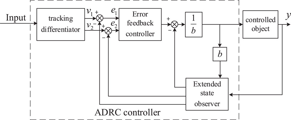
Figure 3. Flowchart of second-order ADRC controller.
Aiming at the difficult problem of ADRC parameter tuning, Linear Active Disturbance Rejection Control (LADRC) proposed by Dr. Gao Zhiqiang’s team is used to adjust the feedforward ADRC controller in (Gao, 2023) this paper.
The expression of a second-order linear differential tracker is as follows:
Where,
Where,
The linear extended state observer of Equation 13 is obtained by using the forward Euler discretization method:
Where,
Where,
Where,
If the extended state observer can realize the error calculation and differential calculation of the system variables, namely,
Finally, the estimated internal disturbance
It is necessary to improve the response speed of the DVR device and suppress the overshoot caused by the controller in the existing control methods. Thus, this paper proposes unifying feedforward compensation and active disturbance rejection control. It constructs a feedforward active disturbance rejection control strategy, which is easy to implement and suitable for engineering practice. This paper takes,
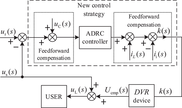
Figure 4. Feedforward active disturbance rejection control block.
4 Simulation and experimental verification
4.1 New control strategy simulation verification and comparative analysis
For the verification of the high response speed and high compensation accuracy of the control strategy proposed in this paper, the mathematical model of the dynamic voltage restorer was built in MATLAB/Simulink, and the working characteristics of the dynamic voltage restorer in the face of voltage sag phenomenon under different control strategies were compared and analyzed.
In the simulation, taking China’s low-voltage AC distribution network as an example, the normal peak voltage of the grid is 311 V and the operating frequency is 50 Hz. At the moment of 0.15 s of simulation, the voltage of the grid is reduced by 50 V (adjusting the peak voltage of the grid to 261 V) and continues for 10 cycles (the duration is 0.2 s), and a slight voltage sag fault occurs in the simulated grid. At the simulation time of 0.35 s, the voltage of the grid is reduced by 100 V (adjusting the peak voltage of the grid to 211 V) and continues for 5 cycles (the duration is 0.1 s), and serious voltage sag failure occurs in the simulated grid. At 0.45 s of the simulation, the grid voltage returned to normal. In order to show the voltage sag problem introduced in this paper more intuitively, the simulation and experimention work waveforms of voltage sag problem of power grid are shown in Figure 5.
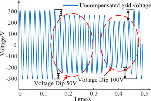
Figure 5. Simulated power grid operating voltage waveform.
In the simulation experiment, the inductance of the low-pass filter of the dynamic voltage restorer is set to 5μH, the capacitance of the low-pass filter is set to 5μF, the transformer ratio is 1:1,
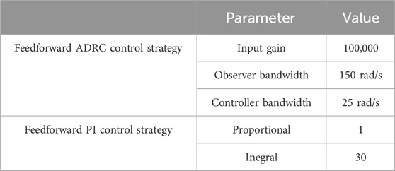
Table 1. Comparison of performance of dynamic voltage restorer under different control strategies.
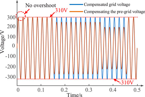
Figure 6. Dynamic voltage restorer before and after compensation under the new control strategy Grid voltage.
As shown in Figure 6, the peak voltage can be guaranteed to be stable around ±310 V after the dynamic voltage restorer compensates the grid voltage. To further quantify the compensation effect of the dynamic voltage restorer under the new control strategy proposed in this paper, the output voltage of the power grid from 0 to 0.5 s (25 cycles in total) was calculated and processed by Fast Fourier Transform (FFT). The calculation results are shown in Figure 7.
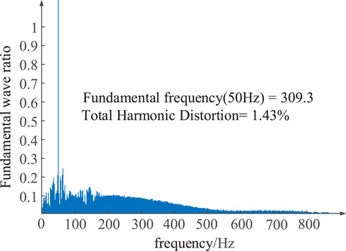
Figure 7. Dynamic voltage restorer compensated voltage FFT results under the new control strategy.
As shown in Figure 7, after compensation by dynamic voltage restorer under the new control strategy proposed in this paper, when voltage sag occurs in the power grid, the voltage fundamental of subsequent equipment can be maintained at 309.3V, with only a fundamental error of 0.7 V. The Total Harmonic Distortion (THD) of the voltage waveform is only 1.43%, which meets the standard that the THD value of the grid voltage is less than 5% in the technical guidelines of GB/T 42,154–2022 power quality monitoring of the distribution network.
For verification of the fast response performance of the proposed method, the load voltage delay after compensation of the DVR system is 90° to construct a virtual two-axis
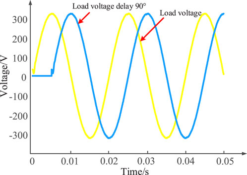
Figure 8. The grid voltage construction of the virtual two-axis
Park transform was calculated for the virtual two-axis
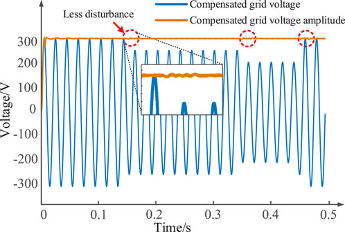
Figure 9. Relationship of voltage amplitude of the power grid after compensation by dynamic voltage restorer based on the new control strategy.
As seen from Figure 9, under the new control strategy proposed in this paper, the dynamic voltage restorer can compensate well for the defects of the voltage amplitude of the power grid, making the user voltage stable around 310 V. In addition, under the new control strategy proposed in this paper, when the grid voltage has a temporary drop, the dynamic voltage restorer has a high response speed, and no obvious overrash phenomenon occurs, which further verifies the stability and rapidity of the proposed control strategy.
For verification of the proposed strategy’s superiority, the feedforward PI control strategy is introduced to compare with the feedforward ADRC control strategy. The grid voltage after voltage compensation of the dynamic voltage restorer under the feedforward PI control strategy is shown in Figure 10.
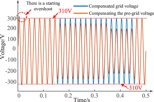
Figure 10. Grid voltage after voltage compensation of dynamic voltage restorer under feedforward PI control strategy.
As seen in Figure 9, under the feedforward PI control strategy, the dynamic voltage restorer can also maintain the power grid’s peak voltage. However, the PI control strategy inevitably has some overkill phenomenon, which reflects that the power grid voltage will over-surge due to the access of the dynamic voltage restorer, causing harm to the electrical equipment at the rear stage. To further compare the compensation effect of the dynamic voltage restorer under different control strategies, the compensated voltage of the dynamic voltage restorer under the feedforward PI control strategy is calculated by FFT, and the calculation results are shown in Figure 10.
As shown in Figure 11, under the traditional feedforward PI control strategy adopted in the control group, it can be seen that the dynamic voltage restorer can only ensure that the voltage fundamental wave of the subsequent equipment is maintained at 307.9V, with a fundamental wave error of 2.1V, and the total harmonic distortion degree of the voltage waveform is 2.49%.
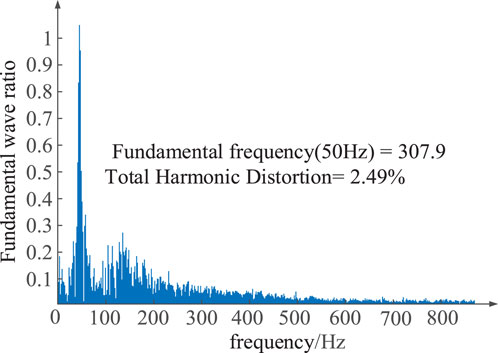
Figure 11. FFT results of the compensated voltage of dynamic voltage restorer under feedforward PI control strategy.
Similarly, a virtual two-axis
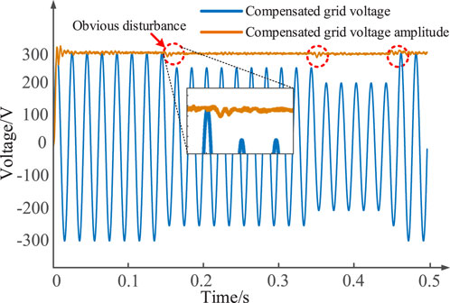
Figure 12. The voltage amplitude relationship of the power network after the dynamic voltage restorer compensation based on the feedforward PI control strategy.
Compared with the voltage amplitude relationship of the power grid after compensation by the dynamic voltage restorer based on the new control strategy, as shown in Figure 9, the voltage amplitude of the power grid after compensation by the dynamic voltage restorer based on the feedforward PI control strategy as shown in Figure 12 has an obvious disturbance in the face of both voltage dips. The dynamic voltage restorer based on the feedforward PI control strategy makes it difficult to achieve a fast and stable voltage compensation response when dealing with rapidly changing power grid voltage fluctuations.
The performance comparison between the dynamic voltage restorer under the feedforward PI control strategy and the new control strategy proposed in this paper is shown in Table 2.

Table 2. Performance comparison of dynamic voltage restorer under different control strategies.
By comparing the data in Table 2, it can be seen that the fundamental amplitude of the proposed control strategy in this paper is 309.3 V, while that of the traditional PI control strategy is 307.9 V. The output result of the proposed control strategy is closer to the standard 310V, which proves that the error of the proposed control strategy is lower. Moreover, the Total Harmonic Distortion of the voltage waveform of the traditional PI control strategy is 2.49%, while the total harmonic distortion (THD) of the proposed control strategy is only 1.43%. It is proved that the proposed control strategy can effectively reduce the power quality pollution caused by harmonic factors in DVR compensation voltage. Through the comparison of the data in Table 2, it can be seen that compared with the traditional control strategy, the dynamic voltage restorer under the new feedforward active disturbance rejection control has better performance indicators in terms of voltage safety, voltage error, and power quality, and can better achieve the task of controlling the power grid voltage sag.
4.2 Comparative analysis of new control strategies bode
For further verification of the superiority of the new control strategy proposed in this paper, this paper analyzes the DVR system using a sweeping frequency method based on the MATLAB platform and obtains the closed-loop Bode of the DVR system. The advantages of quantifiable automatic control theory data of the control strategy proposed in this paper can be directly observed through the sweep method. This paper analyzes the performance of the new control strategy and feedforward PI controller from the three angles of phase margin, amplitude margin, and delay margin in the Bode diagram. Phase and amplitude margin are important factors when designing stability control systems.
In the control system, phase margin is one of the important indexes to evaluate the stability and performance of the system. The phase margin is the gap between the phase Angle of the system and the critical phase Angle. Typically, the greater the phase margin, the more stable the system will be regarding parameter changes and external perturbations. The amplitude margin is the gap between the gain of the system and the critical gain. The greater the amplitude margin, the more stable the system regarding parameter changes and external perturbations. The delay margin depends on the phase margin and unit-gain cross-frequency of the system and is often used to express the maximum time delay that the system can withstand under closed-loop control without causing instability, i.e., the delay margin is the minimum amount of additional delay that the system can withstand at the stability boundary.
This paper uses the frequency sweep method to scan the dynamic voltage restorer under different control strategies. The frequency response data of the system is obtained by applying input signals of different frequencies to the system and measuring the amplitude and phase of the output signals. According to the data obtained by the sweeping frequency, the system can be fitted to the curve, and finally, the transfer function model of the system can be obtained. In the sweeping method, the sinusoidal signal or other input signal of a specific frequency is usually used as the excitation signal, and the output response under different frequencies can be obtained by changing the excitation signal frequency. The gain and phase difference of the system at different frequencies can be obtained by measuring the amplitude and phase of the output signal and comparing it with the input signal. In this paper, the input parameter of the closed-loop controller, that is, the grid voltage dip, is the signal injection point, and the compensation voltage of the DVR system is the output response point of the sweeping frequency method, that is, the output voltage of the DVR system. The excitation signal parameters of the sweeping frequency method used in this paper are shown in Table 3.
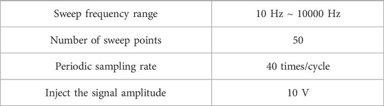
Table 3. Excitation signal parameters of the sweeping frequency method used in this paper.
In this paper, with the 3-order transfer function as the fitting target, the transfer function of dynamic voltage restorer under two different control strategies is fitted by the sweeping frequency method. Among them, the third-order transfer function of the dynamic voltage restorer based on the new control strategy fitted by the sweeping frequency method is shown in Equation 16.
According to the transfer function shown in Equation 16, the closed-loop Bode response diagram of the dynamic voltage restorer based on the new control strategy proposed in this paper can be drawn, as shown in Figure 13.
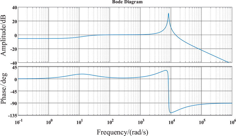
Figure 13. Bode diagram of dynamic voltage restorer based on the new control strategy.
It can be observed from Figure 13 that the dynamic voltage restorer based on the new control strategy has better response characteristics. Its phase margin can reach 150°, and its amplitude can reach 19.2 dB, which meets the stability judgment requirements of a gain margin greater than 6 dB and a phase margin greater than 40° in general engineering.
Then, the dynamic voltage restorer based on the feedforward PI control strategy was fitted with the transfer function under the sweeping frequency method. The third-order transfer function obtained by the dynamic voltage restorer based on the feedforward PI control strategy was fitted with the sweeping frequency method, as shown in Equation 17.
According to the transfer function shown in Equation 17, the closed-loop Bode response diagram of the dynamic voltage restorer based on the feedforward PI control strategy can be drawn, as shown in Figure 14.
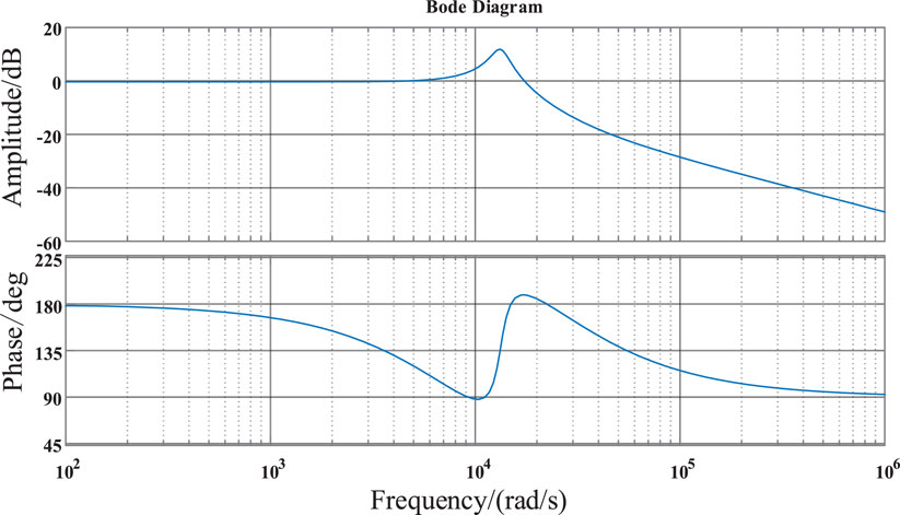
Figure 14. Bode diagram of dynamic voltage restorer under feedforward PI control strategy.
It can be observed from Figure 14 that the dynamic voltage restorer based on the feedforward PI control strategy has good response characteristics, its phase margin can reach 83.3°, and its amplitude can reach 10.2 dB, which meets the stability judgment requirements in general engineering. However, compared with the dynamic voltage restorer based on the new control strategy, the dynamic voltage restorer based on the feedforward PI control strategy has a phase margin of 44.4% less and an amplitude margin of 46.8% less, which reflects the overall performance superiority of the new control strategy proposed in this paper. The performance pairs of dynamic voltage restorers under different control strategies are shown in Table 4.

Table 4. Comparison of performance of dynamic voltage restorer under different control strategies.
4.3 Experimental verification and comparative analysis of new control strategies
To further compare and verify the superiority of the new control strategy proposed in this paper, this paper completes the Hardware In the Loop (HIL) experimental test of the DVR model based on the RT-LAB platform, as shown in Figure 15.
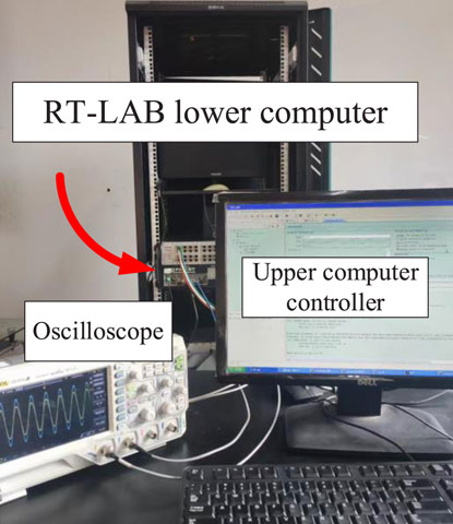
Figure 15. Hardware in the Loop (HIL) experiment platform based on RT-LAB.
Figure 16 shows the experimental waveform of the dynamic voltage restorer based on a feedforward active disturbance rejection controller when it faces the power grid with different scale dips. As can be seen from the amplified part of the waveform in Figure 16, the feedforward active disturbance rejection controller can make the dynamic voltage restorer realize rapid and stable compensation when the grid voltage is temporarily dropped and stabilize the peak value of the grid voltage received by the user side near ±310 V. The harmonic component in the waveform is low. The experimental data can prove that the dynamic voltage restorer based on the feedforward active disturbance rejection controller can stabilize the user side voltage in the process of power grid voltage dip.
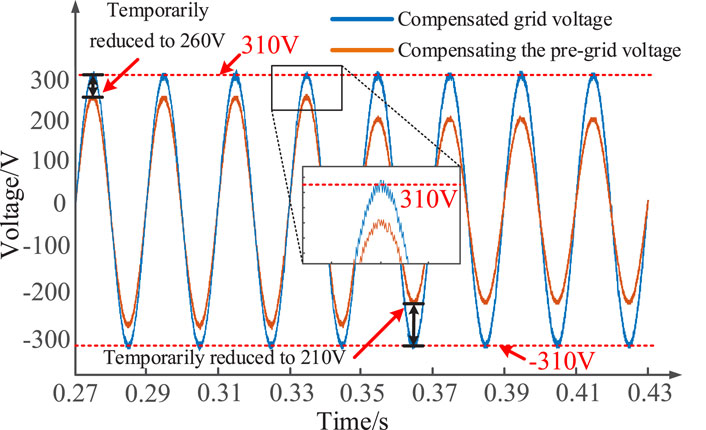
Figure 16. DVR experimental waveform based on feedforward active disturbance rejection controller.
Figure 17 shows the experimental waveform when the dynamic voltage restorer based on the feedforward PI controller faces the power grid with different scale dips. According to the enlarged part of the waveform in Figure 17, compared with the dynamic voltage restorer based on the feedforward active disturbance rejection controller, the dynamic voltage restorer based on the feedforward PI controller can also stabilize the user-side voltage near ±310 V. However, the harmonic component of the compensated voltage is higher.
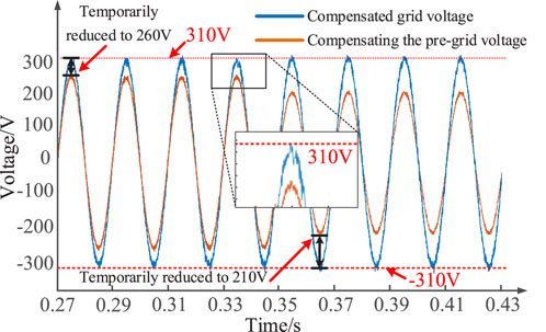
Figure 17. 2DVR experimental waveform based on feedforward PI controller.
The above simulation and experimental results show that compared with the traditional feedforward PI control strategy, the feedforward active disturbance rejection control strategy proposed in this paper can improve the compensation performance of dynamic voltage restorer and verify the effectiveness of the proposed control strategy.
5 Conclusion
There is a contradiction between response speed and the overshooting of traditional DVR controllers. This paper proposes a dynamic voltage restorer control strategy based on feedforward active disturbance rejection control. Through simulation analysis, the following conclusions are obtained.
(1) The new control strategy proposed in this paper combines the advantages of fast response of feedforward compensation method and low overshoot of active disturbance rejection control. Compared with the traditional feedforward PI control strategy, the new control strategy proposed in this paper further improves the response speed of the controller without overshoot.
(2) In this paper, the mathematical model of DVR device is analyzed and a reasonable feedforward compensation control is proposed. Compared with the traditional feedforward PI control strategy, the THD value of the compensating voltage of the DVR device is reduced, thus reducing the pollution of harmonic factors in the compensating voltage of the DVR device to the power quality.
(3) In this paper, three feed-forward loops are introduced on the basis of the active disturbance rejection controller. The response bandwidth of the controller is improved by feed-forward loops, so that the control response speed of the controller is improved, and the voltage dips of different degrees can be compensated quickly.
Data availability statement
The raw data supporting the conclusions of this article will be made available by the authors, without undue reservation.
Author contributions
LH: Writing–original draft, Writing–review and editing. WL: Writing–original draft, Writing–review and editing. NZ: Writing–original draft, Writing–review and editing. QY: Writing–original draft. XW: Writing–original draft.
Funding
The author(s) declare that financial support was received for the research, authorship, and/or publication of this article. This work was financially supported by Hunan Provincial Department of Education Scientific Research Project (22C0305). The funder was not involved in the study design, collection, analysis, interpretation of data, the writing of this article, or the decision to submit it for publication.
Conflict of interest
The authors declare that the research was conducted in the absence of any commercial or financial relationships that could be construed as a potential conflict of interest.
Publisher’s note
All claims expressed in this article are solely those of the authors and do not necessarily represent those of their affiliated organizations, or those of the publisher, the editors and the reviewers. Any product that may be evaluated in this article, or claim that may be made by its manufacturer, is not guaranteed or endorsed by the publisher.
References
Appala, T. N., Raj, S. A., Rakesh, M., and Sanjeevikumar, P. (2021). Variable fractional power-least mean square based control algorithm with optimized PI gains for the operation of dynamic voltage restorer. IET Power Electron. 14 (4), 821–833. doi:10.1049/pel2.12067
Arya, S. R., Mistry, K. D., and Kumar, P. (2024). DVR using randomized self-structuring fuzzy and recurrent probabilistic fuzzy neural-based controller. J. Institution Eng. (India) Ser. B 105 (3), 483–502. doi:10.1007/s40031-023-00973-1
Ben-run, H., Li, X., Zheng-Guo, W., and Wei-Ping, Z. (2012). Application of active disturbance rejection controller in dynamic voltage restorer. Electr. Mach. Control 16 (06), 106–110.
Chen, Z., Song, M., and Liu, S. (2022). Factors influencing the test results of voltage sag immunity. Med. Equip. 35 (21), 37–39. doi:10.14044/j.1674-1757.pcrpc.2022.02.018
Deshpande, C. V., Chilipi, R., and Arya, S. R. (2024). Modified fractional least mean square-based control scheme for dynamic voltage restorer to improve power quality. Electr. Eng. 106 (4), 5069–5087. doi:10.1007/s00202-024-02270-6
Gao, Z. (2023). Inheritance and development of active disturbance rejection control. Control Theory Appl. 40 (03), 593–595.
Gu, Y., Cheng-Jian, L., Yao, X., Fang, J. L., and Sheng, H. (2020). Research and application of Power Supply service effectiveness Improvement based on Power quality fine control. Electr. Appliances Energy Effic. Manag. Technol. 593 (8), 94–99. (in Chinese).
Guan, W., Qinglei1, Z., Siyuan, Z., Kaiwen, H., Boyu, Q., and Zhengchun, D. (2023). Research on Evaluation System of grid structure considering load loss. New Technol. Electroengineering Electr. Energy 42 (01), 40–47.
Hong, C., and Zhun, Y. (2022). Overview of power quality analysis. China Insp. Test. 30 (05), 11–14. doi:10.16428/j.cnki.cn10-1469/tb.2022.05.003
Huiyu, J., Song, J., Lan, W., and Gao, Z. (2020). On the characteristics of ADRC: a PID interpretation. Sci. China Infor- mation Sci. 63 (10), 258–260.
Jerin, A. R. A., Palanisamy, K., Umashankar, S., and Sanjeevikumar, P. (2017). Improved Fault ride through capability in DFIG based wind turbines using dynamic voltage restorer with combined feed-forward and feed-back control. IEEE Access (99), 1.
Kang, W., Jun, L., Haotong, L. I., Li, L., and Boyu, Q. (2022). Parameter optimization of low-voltage trip device for reducing transient load loss. New Technol. Electroengineering Electr. Energy 41 (10), 65–72. doi:10.12067/ATEEE2109002
Kumar, P., Arya, S. R., Mistry, K. D., and Giri, A. K. (2021). Hybrid self-learning controller for restoration of voltage power quality using optimized multilayer neural network. Int. J. circuit theory Appl. (12), 49.
Li, D., and Zhao, D. (2022). Single current feedback control strategy of an LCL grid-connected inverter based on GI-ESO and delay compensation. Energies 15, 2893. doi:10.3390/en15082893
Li, P., Xie, L., Han, J., and Pang, S. (2018). A new voltage compensation philosophy for dynamic voltage restorer to mitigate voltage sags using three-phase voltage ellipse parameters. IEEE Trans. Power Electron. (2), 1154–1166. doi:10.1109/tpel.2017.2676681
Liu, Y., and Tang, W. (2019). Hazards of typical power quality disturbance in papermaking enterprises and its monitoring and treatment measures. China Pap. Mak. 38 (12), 72–77. doi:10.11980/j.issn.0254-508X.2019.12.012
Ma, L., Chen, Y., Zhang, Y., Chen, Y., Li, Y., Lou, J., et al. (2023). Evaluation of severity of multistage voltage sag based on improved analytic hierarchy process. Power Syst. Prot. Control 51 (17), 49–57. doi:10.19783/j.cnki.pspc.221734
Ma, Y., Yang, L., Zhou, X., Yang, X., Zhou, Y., and Zhang, B. (2020). Linear active disturbance rejection control for DC bus voltage under low-voltage ride-through at the grid-side of energy storage system. Energies 13, 1207. doi:10.3390/en13051207
Shukir, S. S. (2021). Comparison the performance of the dynamic voltage restorer based on PI, fuzzy logic, and fuzzy neural controller. Int. J. Eng. Manag. 5 (1), 1. doi:10.11648/j.ijem.20210501.11
Wan, L., and Yuzhen, X. (2022). Improved single-cycle control based on linear active disturbance rejection. Electr. Appliances Energy Effic. Manag. Technol. 0 (4), 19–27. doi:10.16628/j.cnki.2095-8188.2022.04.004
Wang, S., and Pei, Y. (2022). Midpoint potential Balance problem of three-level dynamic Voltage restorer. Power Electron. Technol. 56 (04), 113–117.
Xin-Xin, M., Jun-Peng, D., Risheng, Q., and Haobo, H. (2022). Research on control strategy of single-phase dynamic voltage restorer. Power Electron. Technol. 56 (02), 110–114.
Ying, W., Xinliao, J., Yunzhu, C., Xianyong, X., and Wenxi, H. (2023). A voltage dip data generation method considering Non-uniform Distribution. Power Grid Technol. 47 (07), 2936–2949. doi:10.13335/j.1000-3673.pst.2022.1704
Yu, Y., Kong, M., Yan, J., and Lu, Y. (2023). Optimization strategy for output voltage of CCM flyback converter based on linear active disturbance rejection control. Appl. Sci. 13 (23), 12786. doi:10.3390/app132312786
Zhang, P., Fangwei, X., Chengrui, L., Hongru, Z., and Lin, X. (2022). Voltage dip source location based on perturbation power wavelet singular entropy. Intell. Electr. Power 50 (10), 30–36+44.
Keywords: dynamic voltage restorer, voltage sag, feedforward compensation, active disturbance rejection controller, power quality management, distribution network
Citation: Huang L, Liu W, Zhang N, Yan Q and Wei X (2025) Modulation strategy of dynamic voltage restorer based on dual-feedforward active disturbance rejection compound controller. Front. Energy Res. 12:1462565. doi: 10.3389/fenrg.2024.1462565
Received: 10 July 2024; Accepted: 21 November 2024;
Published: 31 January 2025.
Edited by:
Xiaohu Yang, Xi’an Jiaotong University, ChinaReviewed by:
Prashant Kumar, Symbiosis Skills and Professional University, IndiaVinay Kumar Awaar, Gokaraju Rangaraju Institute of Engineering and Technology (GRIET), India
Copyright © 2025 Huang, Liu, Zhang, Yan and Wei. This is an open-access article distributed under the terms of the Creative Commons Attribution License (CC BY). The use, distribution or reproduction in other forums is permitted, provided the original author(s) and the copyright owner(s) are credited and that the original publication in this journal is cited, in accordance with accepted academic practice. No use, distribution or reproduction is permitted which does not comply with these terms.
*Correspondence: Weiling Liu, bnVsbHdlaWxpbmdsaXUxNjNAMTYzLmNvbQ==