- 1Electrical and Electronics Engineering, M. Kumarasamy College of Engineering, Karur, India
- 2Electrical and Electronics Engineering, Karpagam College of Engineering, Coimbatore, India
- 3Department of Electrical Engineering, College of Engineering, King Saud University, Riyadh, Saudi Arabia
The current electric vehicle domain is increasingly focused on fuel cell technologies due to its flexibility, steady supply of power, low atmospheric pollution, increased startups, and rapid responses. Fuel cells exhibit nonlinear power versus current characteristics, making it challenging to extract maximum peak power from the fuel stack. To address this, this work introduces an adaptive Coati Optimization algorithm combined with a Tilt-integral-derivative (TID) controller (TID-ACOA) to find the maximum power point (MPP) of the fuel stack systems, ensuring maximum power extraction. The proposed MPPT controller is compared with other MPPT controller, including PI, TID, and TID-COA. Comprehensive evaluations are conducted on tracking current, voltage, maximum power extraction, MPPT controller efficiency, converter voltage settling time, and oscillations. The fuel stack’s low output voltages are enhanced using a boost DC-DC converter, and the entire fuel stack-fed boost converter systems is modeled using MATLAB/Simulink. Simulation result show that the TID-ACOA MPPT controller achieves higher MPP tracking efficiency compared to conventional controllers.
1 Introduction
Recently, the emphasis on renewable energy generation has surged due to the rising costs of conventional fossil fuel and the anticipated depletion of their reserve (Rafikiran et al., 2023; Touti et al., 2024; Srinivasan et al., 2021). Among the renewable resources, solar and wind energy are particularly appealing to both power producers and researchers (Tiwari and Babu, 2016a; Tiwari and Babu, 2016b; Krishnamurthy et al., 2019; Xiong et al., 2019). Nevertheless, hybrid energy sources are inherently intermittent one, with their output power heavily reliant on solar irradiations and wind speeds, respectively (Kumar et al., 2017; Reddy and Natarajan, 2018; Tiwari and Babu, 2017; Liu et al., 2020). To ensure a stable supply of power, enhanced storage solutions, such as super capacitor, battery and FC are essential. Of these options, FC power generation stands out for its high efficiencies and power density. FCs are devices that convert the chemical energies of a fuels (often hydrogen) and an oxidizing agents (typically oxygen) directly into electricity through an electrochemical process. They offer numerous advantages, such as excellent efficiencies, maximum density of power, and a flexible modular structures. FCs are classified based on the type of electrolytes they employ, including Alkaline Fuel Cell (AFC), Phosphoric Acid Fuel Cell (PAFC), Proton Exchange Membrane Fuel Cell (PEMFC), and Molten Carbonate Fuel Cell (MCFC) (Kumar et al., 2017). Among these, PEMFCs are particularly favored in electrical applications due to their characteristics of low noise generation, maximum power density, and compact size (Kumar et al., 2021). The PEMFC stands out due to its notable advantages, such as maximum efficiency, minimum operating temperature, rapid start-up, and lightweight construction, making it highly suitable for automotive applications (Hwang et al., 2015). Despite its relatively low output voltages, especially for FCEVs, DC-DC converters are essential to elevate the voltage for interfacing with battery storage systems. Moreover, PEMFCs generate electricity through an electrochemical reaction between H2 and oxygen, which means they function as nonlinear dynamic systems (Rosas-Caro et al., 2017).
The electrical power produced by PEMFCs is not constant; rather, it reaches maximum efficiency at a specific operating point under varying condition, such as membranes moisture, cell temperature, and H2/O2 ratio. In designing efficient battery chargers like step-up DC-DC converters for FC vehicles, an effective MPPT controller plays a crucial role. It optimizes power converters by adjusting their duty cycles to maximize power output (Harrag and Rezk, 2021; Akter et al., 2022; Rezk et al., 2021). Enhancing energy efficiency in FC systems through MPPT controllers is more cost-effective and straightforward compared to improving electrode electro-catalytic and membrane properties. Consequently, various MPPT methods have emerged, including Perturb and Observation (P&O) (Mayo-Maldonado et al., 2019), neural network-based approaches (Babu and Ponnambalam, 2018), Increment Conductance’s (IC) (Haroun et al., 2014; Tiwari et al., 2018; Shahin et al., 2010a), Fractional Open Circuit Voltage (FOIC) (Shahin et al., 2010b), voltage-based methods (Alcazar et al., 2008), water cycle algorithms (Tofoli et al., 2012), and others, in recent years. These advancements highlight ongoing efforts to achieve optimal performance and efficiency in FC electric vehicles (Li et al., 2012) through advanced control strategies. In (Hsieh et al., 2011), a hybrid MPPT controller was proposed to enhance efficiency and minimize steady-state oscillations in FC systems. This controller integrates neural network (NN) and variable step size incremental conductance (IC) methods. Another approach presented in (Inci and Caliskan, 2020) involves a hybrid MPPT controller using the PSO algorithm and PID controller to adjustment the operation point of PEMFC system. However, traditional PSO algorithms suffer from delayed response to operational changes. Despite these advancements, existing techniques have limitations, particularly in automatically acquiring and optimizing the parameters, such as MFs and rules. Although MPPT methods have garnered attention for FC systems, research addressing adaptive MPPT tuning for improved computational efficiency is lacking (Bayat and Baghramian, 2020; Kart et al., 2024).
1.1 Motivation
FCs has risen as superior alternatives to combustion-based power source, gaining prominence in automobile, public transportation, and maximum power generation applications over recent decades. However, optimizing power extraction from FC stacks remains a significant challenge. Achieving maximum power point (MPP) tracking involves balancing implementation costs with accuracy, results a critical focus for researchers. This ongoing challenge underscores the necessity for advanced MPPT controllers tailored specifically for FC system.
The research’s primary contributions are:
• To create an innovative design Optimization based approach for MPPT control of PEMFCs with accurate tracking.
• To propose a novel ACOA Algorithm that surpasses previous methods by delivering substantial advantages in optimizing parameters for TID controllers.
• To evaluate and contrast the effectiveness of the suggested approach with the latest optimization techniques to validate its performance.
Organization of the paper:
The manuscript is arranged as follows: The latest study on issue related to enhanced MPPT control of FC is present in Section 2. The proposed methodology for MPPT control of FC is discussed in Section 3, followed by which detailed explanation of proposed control approach in discussed in Section 4. Section 5 discusses the outcome obtained using the proposed methodology and the paper is detailed in Section 6.
2 Literature review
2.1 Related works
In 2023, Rafikiran et al. (2023) illustrated a PEMFC system to evaluate MPPT techniques across varying operating temperatures. The authors studied hybrid controllers like AA-based P&O, VS-based RBFCD and VSGWA-fuzzy methods under static and dynamic conditions. The variable optimization using the fuzzy logic controllers showed superior performances, tracking MPP accurately and handling temperature changes effectively.
In 2024, Touti et al. (2024) introduced an Adaptive Genetic Algorithm (AGA) combined with an ANFIS for MPPT in fuel cell system. The study comprehensively evaluates the controllers in term of MPP tracking speeds, oscillation at MPP, voltage converter settling times, peak power extraction, and MPPT controller efficiency. The inherently low output voltage of fuel cells is augmented using a DC-DC converter. Simulation results demonstrate that the AGAD with ANFS MPPT controllers achieves superior MPP tracking efficiencies compared to other controllers.
In 2020, Srinivasan et al. (2021) suggested a new MPPT control system using RBFN for FC energy converting system. The authors investigated various MPPT methods, including P&O and fuzzy logics, paired with DC/DC converters like variable Boost and Quadratic Boost converters. The primary goal was to enhance output power and optimize the performance of FC under diverse operating conditions. A reconfigurable variable Boost converter was employed to achieve high voltage performance, enabling operation at elevated voltages and improving overall system performance. The study compared this new configuration with traditional Boost and Quadratic Boost converter setups to validate its effectiveness. Results indicated that controllers with the reconfigured variable quadratic Boost converters outperformed P&O and FLC methods in maximizing power extraction. Notably, the RBFN controller demonstrated faster settling times and fewer oscillations during sudden changes in input conditions, highlighting its superiority in dynamic response.
In 2020, Kumar et al. (2021) introduced a 1.26 kW FCs-fed EV system featuring a reconfigurable QBC and a neural network-based MPPT algorithm. The increasing adoption of electric vehicles is crucial for reducing environmental pollution caused by traditional combustion engine vehicles using fossil fuels. The integration of PEMFC with brushless DC (BLDC) motor utilized a specially designed Quadratic Boost Converter to achieve high converter voltage gain. The performances of the system were calculated using the P&O methods and compared with the results obtained using the NN-based MPPT control under varying fuel cell input temperatures across different operational periods.
In 2020, Bayat and Baghramian (2020) introduced an innovative self-tuned type-2 fuzzy MPPT controllers designed to optimize battery charger efficiency while minimizing costs. This controller focuses on regulates the switch duty cycles of the power converter under uncertain conditions, ensuring maximum power extraction from the FC system. It also maintains the battery at peak charge levels while preventing overcharging. To enhance computational efficiency, the authors developed an improved invasive weeds optimization algorithm (EIWO) to adjust type-2 fuzzy set parameter. The study utilized MATLAB for data processing and simulation of the MPPT Type-3 fuzzy controllers. Experimental testing with a prototype device validated the controller’s performance.
In 2021, Harrag and Rezk (2021) introduced a novel hybrid P&O and type-3 fuzzy-based adapted stepping size MPPT method for PEMFC systems. This approach aims to enhance the dynamic responses and minimize the steady-state oscillation around the MPP. The type-3 fuzzy logic adjusts the step size of the traditional P&O algorithms to maximize power extraction from PEMFC systems. The hybrid controller was validated using MATLAB, simulating an 8 kW PEMFCs system power a resistive load via a DC-DC boost converter.
In 2022, Akter et al. (2022) introduced a robust nonlinear controller for a PEMFC coupled with a boost converter. The controller focuses on maintaining a stable voltage and enhancing transient stabilities. The method employs a nonlinear robust ITSMC, incorporating a unique sliding surface to capture dynamics from input voltage and load variations. A tailored law ensures finite time convergence while minimizing chattering effects. Using Lyapunov control theory, the study assesses the large-signal stability of boost converters under the proposed controller, demonstrating superior performance in reference tracking with minimized overshoot and robustness against disturbance compared to traditional ITSMC approaches.
In 2021, Rezk et al. (2021) introduced an enhanced approach for designing Fuzzy Logic Controls (FLC) system aimed at MPPT in PEMFC. The method utilizes an Evolutionary Optimization (EO) technique to determine optimal FLC parameters, focusing on maximizing tracking accuracy and speed. During optimization, the gains of FLC membership function are treated as variable, with the integrals of error serving as the objective function. Comparative analysis against PSO, GA, ECPO, and SHO methods demonstrated that the EO approach consistently outperformed others in terms of mean, median, variance, and standard deviation metrics.
2.2 Problem statement
Studies emphasize the upfront installation costs and operational expenses associated with renewable energy systems. It is argued that these systems offer superior economic advantages compared to traditional non-renewable sources. However, renewable energy generations can be variable under different peak demand scenarios. The Hybrid ANFIS MPPT Controllers for PEMFC-Fed EV System demonstrates superior MPPT efficiency compared to several other hybrid controllers. While this hybrid approach improves efficiency, it may come with higher implementation costs due to the need for additional components and computational resources. The Adaptive Hybrid ANFIS MPPT Controller combines AGA with ANFIS for MPPT. The ANN based MPPT technique for PEMFC may struggle to accurately model and predict the complex nonlinear relationship between input variables (such as voltage, current, and temperature) and power output. In recent times, FC fed reconfigured quadratic boost converters with the NN based MPPT algorithm is utilized. However, the reconfigured quadratic boost converter introduces additional complexity compared to conventional boost converters. An improved self-tuned type-2 fuzzy MPPT controllers is utilized to produce a maximum-efficiency and minimum-cost battery charger. But, the implementation of a self-tuned type-2 fuzzy MPPT controllers involves complex algorithms and computations. However, lack of interpretability may hinder diagnostic efforts and fine-tuning. The NITSM Controllers for PEMFC with DC-DC Boost Converters are robust, but can introduce high-frequency switching and chattering effects. For finding the optimum parameter to benefit the inherent flexibilities, a design which is based on recent Optimization method is developed. However, most optimization algorithms may get stuck in local optima, especially when dealing with complex numerical or engineering problems. Limitations of the research works are;
• There is a shortage of research progress on the best MPP Tracking for PEMFC system technologies with high accuracy.
• The development of controllers for MPPT in FC-connected systems did not get significant attention.
• Not enough information exists regarding how the integration of optimization with the controller architecture offers a promising approach for MPPT in FC.
An Adaptive Coati optimization with TID controller strategy for PEMFC has been offered in this research to fill this gap. The suggested structure would strengthen accurate power tracking by utilizing an optimized MPPT controller approach, while the performance of the framework could be evaluated in connection to the impact on the accuracy of tracking with FC.
3 Proposed methodology of MPPT extraction in fuel cell
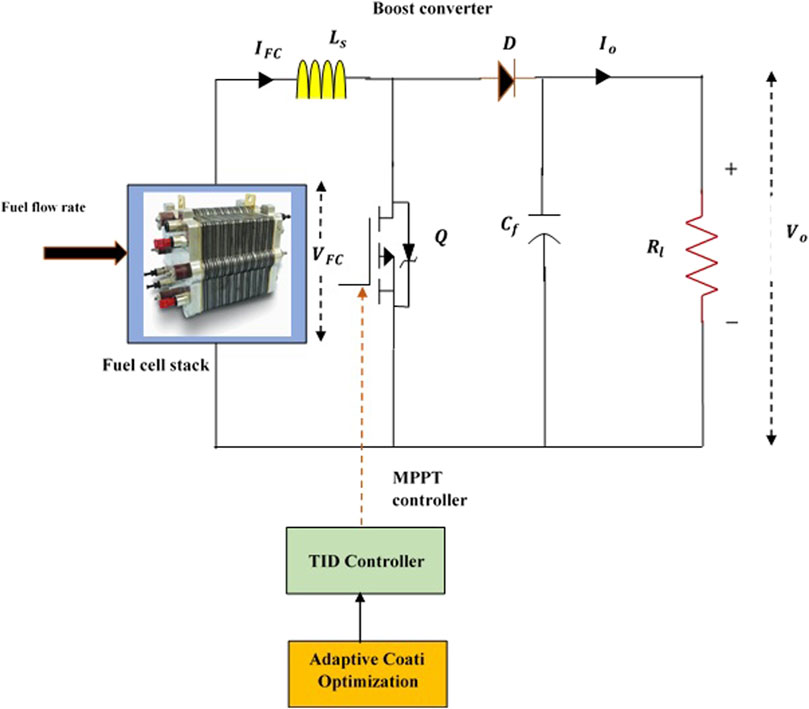
Fuel cell based power generation is widely adopted in the automotive sector as it is a prominent renewable source due to clean energy profile and minimal environmental impact. The output power of an FC system hinges significantly on the fuel flow rate, and its voltage-current characteristics are nonlinear, complicating the task of extracting maximum power from the fuel stacks.
To address this challenge, a MPPT controller is employed across the fuel flow rate condition of the FC to optimize power extraction. The MPPT controllers interface with a boost step-up converters, which efficiently increases voltages to a desired point determined by the duty cycle. Effective controlling the converters ensuing a precise regulation of the output voltages from the FC. The converter serves dual purposes, such that it steps up the input voltages and implements MPPT control based on calculated electrical signal from the FCs system.
Figure 1 illustrates the framework of the proposed system. This study introduces a TID controller strategy for FC aimed at MPPT control. The approach utilizes the ACOA method to optimize controller parameters, leveraging the inherent flexibility of TID systems for precise and rapid tracking. The optimization focuses on adjusting the parameters, such as
3.1 Modelling of PEMFC
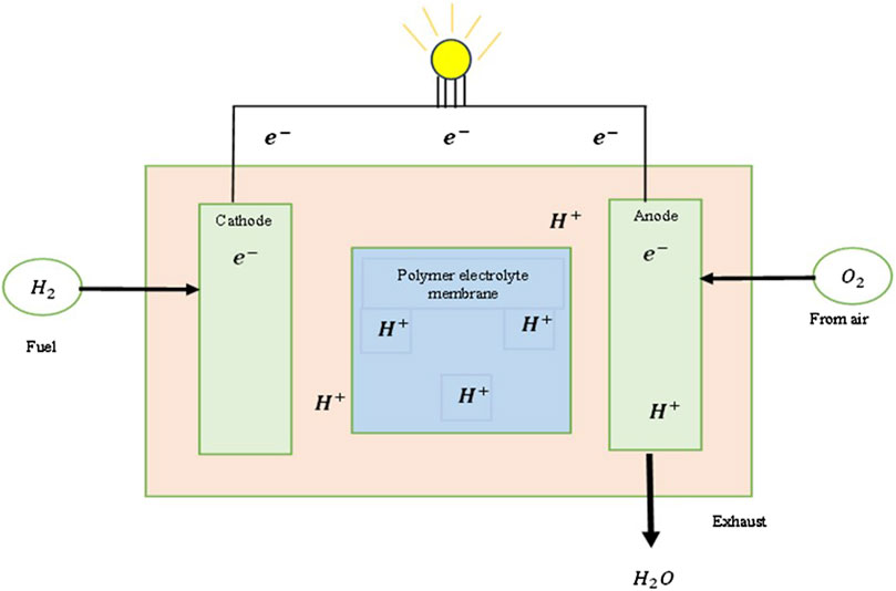
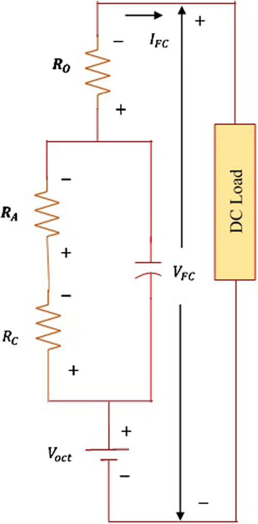
The RES exhibit non-linear power characteristics with significant distortions. Hybrid energy power systems often struggle to provide consistent and efficient power to electric vehicle (EV) systems. Consequently, modern EV manufacturers are increasingly turning to Fuel Cell (FC) technology due to its appealing attributes, such as reliability, continuous power supply, robustness, and minimal environmental impact (HussaianBasha et al., 2022). This study focuses on utilizing PEMFCs to efficiently power EV systems. PEMFCs offer advantages like rapid startup, operation at low temperatures, and quiet operation without rotating parts that generate noise pollution, and also entail lower maintenance costs. However, PEMFCs are costly to implement and operate. Figure 2 illustrates the overall operation of PEMFCs, while Figure 3 depicts their corresponding circuit.
In Figure 2, the FC input sources are H2 and O2, which are fed to the anodes and the cathode of the PEMFCs. Here, H₂ is split into ions and releases electrons that collect in the external load circuits.
Equations 1, 2 indicate that the electricity produced by a single FCs
where,
where,
3.2 Modelling of DC-DC boost converter
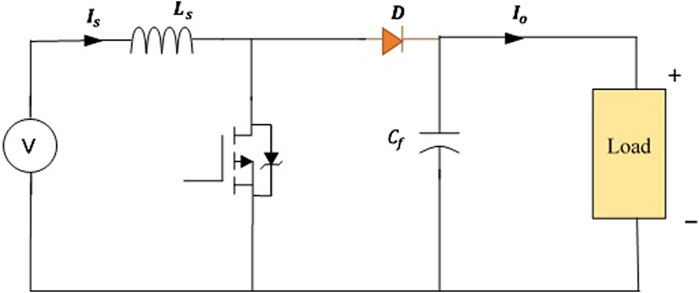
DC-DC Boost converters are employed to elevate primary DC voltages while maintaining a constant output voltage despite varying load demands. The duty ratio
To ensure consistent conductivity and equal current distribution across loads, it is essential to understand both critical inductance and critical capacitance parameters Equations 17, 18.
Where,
The minimum capacitance values at which the voltage property of the capacitors remain valid is denoted as
4 Control technique
In this work, an ACOA tuned TID controllers is used for finding the MPP of the fuel stack systems thereby extracting the maximum peak powers from the FC.
4.1 ACOA method
This section discusses the proposed ACOA method and provides a mathematical simulation of its various steps (Dehghani et al., 2023).
4.1.1 Coati actions as motivation
The coatis use cunning conduct to pursue and avoid predatory creatures and to pursue and kill Iguanas. The imitation of these coatis’ genuine actions served as the primary inspiration for the layout used in the ACOA technique.
4.1.2 Algorithm initialization method
The coatis were considered a socioeconomic element to the community-oriented ACOA technique. By determining that each coati is located within the targeted region, the amounts utilized in choosing variables have been determined. Therefore, Coatis’ viewpoint indicates an alternative to the problem stated in the ACOA. Equation 19 shall be used to determine the initial location for a coati inside the search zone based on the ACOA installation’s beginning location.
where,
Based on ACOA, the coati communities are computationally characterized using the following matrix, also known to be the communal matrix
As a result of determining potential solutions within preference variables, several factors related to the problem’s objective function are evaluated. Equation 21 is used to illustrate the values.
where,
4.1.3 Mathematical structure of ACOA
According to ACOA, the basis for improving a coatis’ candidate solution positioning involves imitating two different coatis’ actions in the environment. These actions consist of:
i) The techniques employed by coatis to attack iguanas.
ii) The methods they use to escape predators.
4.1.3.1 Phase 1: Iguana following with a strategy of attack (phase of exploration)
The initial stage of increasing the coati groups around the search area has been modeled using an assault approach that includes coatis against iguanas. This is the method used by a coatis group to approach and intimidate an iguana. When the next coati gathers around the iguanas as they approach their areas, someone waits beneath a tree. Coatis may relocate throughout the hunting zone, showcasing the ACOA’s capacity for global problem-solving in the area of solution-seeking.
The iguana is thought to be one of the most advantageous residents in the ACOA layout. Furthermore, it is thought that half of these coatis scale the branches while the other waits patiently for the iguanas to descend to the ground. To replicate the location of the coatis as they emerge from the branches, Equation 22 is used.
The iguanas were tossed to the ground and dropped in an arbitrary location within the hunting area. Equations 23, 24 are utilized to simulate the coatis on the ground will move within the seeking zone based on such a randomized position.
If coati’s new location results satisfy the objective function, the adaptation process is applicable; if not, the coati stays in its previous location. Modeling of Equation 25 shows that the condition varies over n = 1,2, … , I.
This
4.1.3.2 Phase 2: Behaviour of predators running away (exploitation phase)
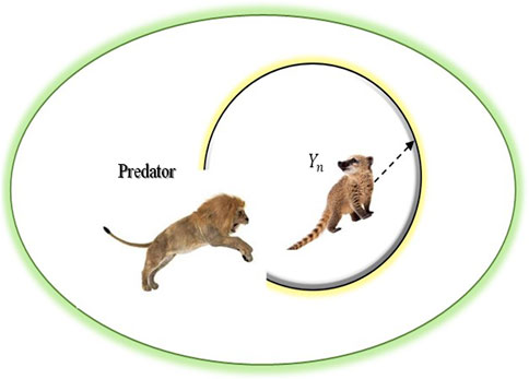
The subsequent phase of improving coati location in the search space was predicted statistically based on coati’s typical behaviour when confronting and evading predators. Coati’s actions inside this plan have caused it to come with an appropriate spot near to where it is currently located, which demonstrate the ACOA’s capability over regional exploitation. The illustration of a coatis evades a predator during ACOA’s phase after initial stage is shown in Figure 5.
Equations 26, 27 have been used to establish a randomly selected positioning close to where each coati resides in order to replicate this behavior.
This is appropriate when the improved computed locations increase the quantities related to the intended operation, which the scenarios generate with the help of the Equation 28.
where,
4.1.4 Termination
A complete ACOA recitation occurs when all coatis in the seeking area have had their spots altered in accordance with the first and subsequent phases. the population revision derived from Equations 22–28 is maintained till the final iteration of the operation. The finest outcome obtained during all iterations of the method constitutes the best solution.
4.1.5 ACOA with oscillating inertia weight strategy
In the optimization procedure, the oscillating inertia weight strategy employs a method where alternating phases of exploration and exploitation create a cyclic pattern (Ozbay and Alatas, 2021).
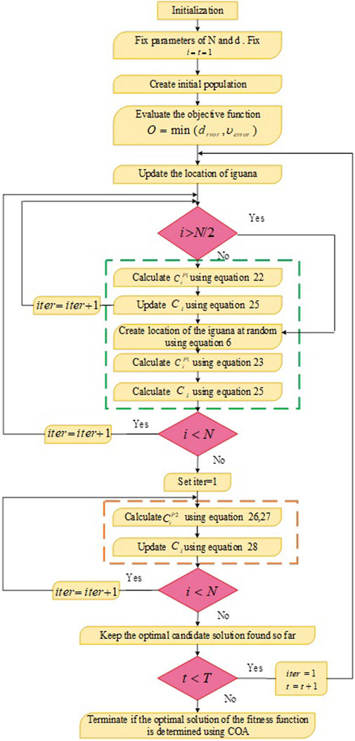
This oscillating approach utilizes a sinusoidal function to dynamically adjust the parameters during the search process. The procedure pseudo code of the proposed system is given in Algorithm 1, and the flowchart of the algorithm is shown in Figure 6.
Algorithm 1.Pseudocode of proposed ACOA algorithm.
Step 1 Set up the original coati positions
Step 2 Initialize the coati’s number
Step 3 For
Step 4 Changing the Iguana’s location will determine where the best fraction is located.
Phase 1: Exploration phase
Step 5 For
Step 6 Equation 22 can be used to identify the original place of the
Step 7 Using Equation 25 change the position of the
Step 8 End for
Step 9 For
Step 10 Equation 23 can be used to decide the iguana’s randomized location.
Step 11 Equation 24 can be used to identify the original place of the
Step 12 Using Equation 25 change the position of the
Step 13 End for
Phase 2: Exploitation phase
Step 14 Equation 26 can be used for calculating the agents’ regional boundaries.
Step 15 For
Step 16 Using Equation 27 find original place of the
Step 17 Equation 28 should be used to change where the
Step 18 End for
Step 19 Update the value of the parameters using Equation 29
Step 20 Return the best response
Step 21 End for
Step 22 Modify optimal solution
Step 23 End
4.2 TID controller
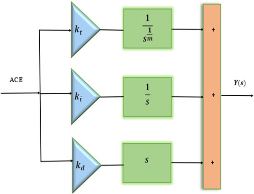
The TID controller integrates three distinct gain terms, such as tilt gain, integral gain, and derivative gain in configurations (Elkasem et al., 2022). The TID controller is an FOC designed using principles from fractional-order calculus. The tilt terms, similar to the proportional terms in a PID controllers, incorporates an additional tuning parameter
where,
5 Results and discussion
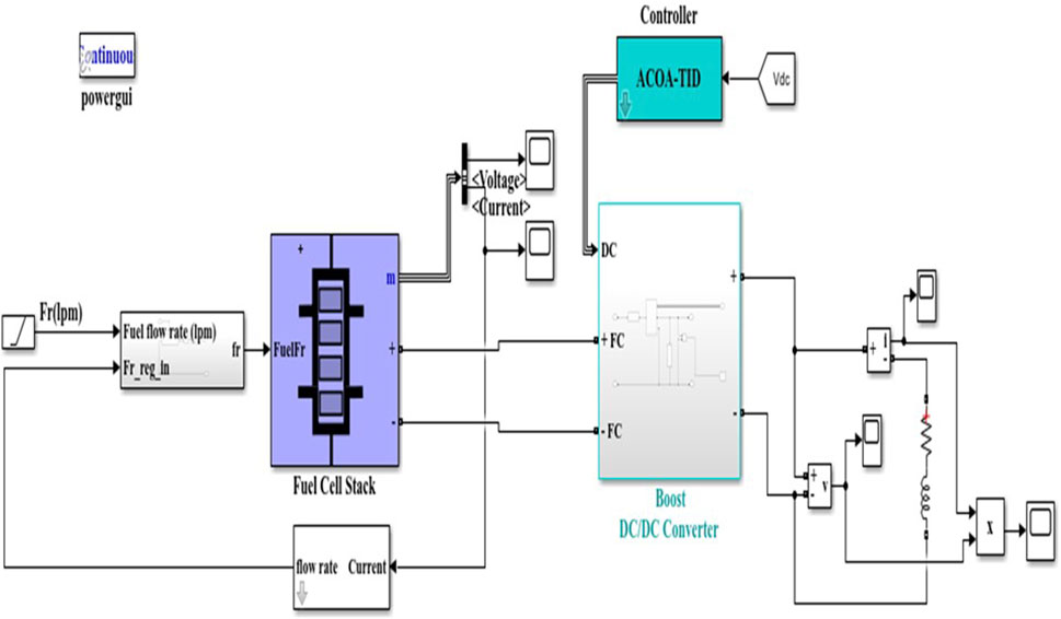
The proposed system of FC system with boost converter and an optimized TID controller has been demonstrated using the MATLAB model. Figure 8 show the simulation model of the suggested work. The suggested framework was evaluated using fuel flow rate analysis. By incorporating output power and efficiency instances, the suggested model was contrasted with existing approaches including PI, TID, and TID-COA where the voltage source, current source, and fuel flow rate are detected as independent indicators.
5.1 Evaluation of current and voltage
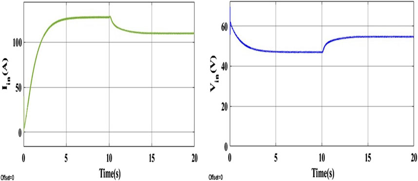
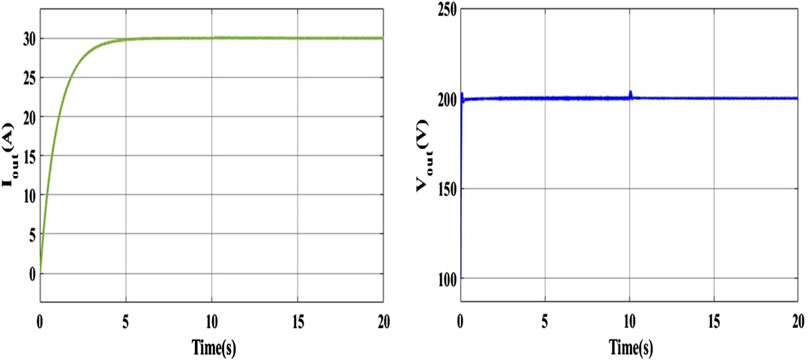
The input current and voltages waveform of the PEMFC system are presented in Figure 9. The Input current gradually increases from zero to 128 A with the fuel flow rate of 50 lpm. After 10 s, current level decreases its value and maintained at 109.3 A with the fuel flow rate of 85 lpm. Input voltage decreases from 60V to 47 V with the fuel flow rate of 50 lpm. After 10 Sec, voltage level increases its value and reaches 55 V with the fuel flow rate of 85 lpm. The output current and voltage waveform of the PEMFC systems is displayed in Figure 10. Input current gradually increases from zero to 30 A at the time of 5 s. After 5 s, current level is maintained at 30 A. The final voltage is maintained at 200 V with the fuel rate flow of 50 lpm and 85 lpm. At the time of 10 s, small spike occurs due to the fuel flow rate change.
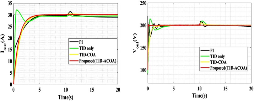
The comparative analysis of output current and voltages using different models are shown in Figure 11. The proposed TID-ACOA system is compared with the conventional methods, like PI, TID and TID-COA. From the evaluation, it is found that the proposed method’s output current and voltage waveforms are smooth than the conventional methods. Voltage spike and current spike occurs in PI, TID and TID-COA methods. Output current and voltage of the proposed method is attained to be 30A and 200 V respectively, which is maximum than the other comparative method.
5.2 Evaluation of output power
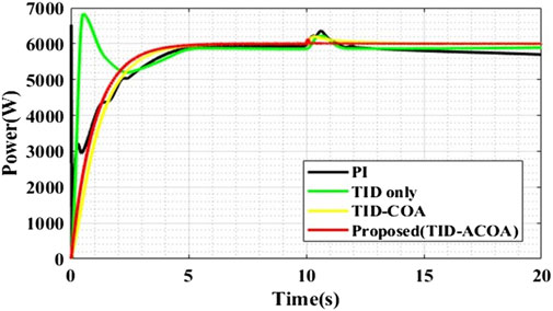
The output power of the proposed systems is displayed in Figure 12. The output power gradually increases from 0 to 6000W at 5 s. After 5 s, the power level maintained as 6000W. At 10 s, small spike occurs due to the change of fuel flow rate from 50 lpm to 85 lpm. The comparative analysis of varying output power of varying FC models is shown in Figure 13. The proposed TID-ACOA system is compared with the conventional methods, like PI, TID and TID-COA. From the evaluation, it is found that the proposed method’s output power waveform is better than the conventional methods. More spikes were noticed in conventional methods, like PI, TID and TID-COA methods. Output power of the proposed methods is 6000 W, which is higher than the other comparative methods.
5.3 Convergence analysis
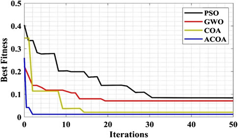
The convergence of the ACOA system is comparing with the conventional method, like PSO, GWO and COA, and is shown in Figure 14. From the evaluation, the convergence speed of the proposed ACOA methods is 50% maximum than the COA method, 85.7% greater than the GWO methods, and 88.23% superior to the PSO methods. This shows that the proposed methods have best fitness than the conventional methods.
5.4 Analysis of fuel flow rate
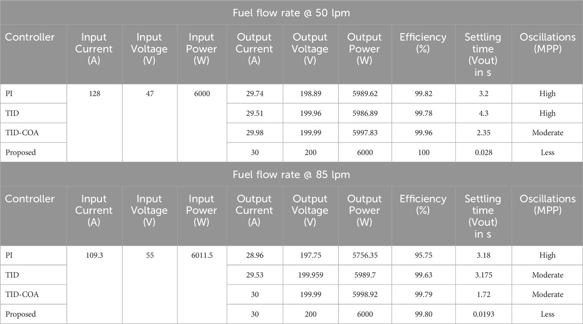
The proposed system is evaluated by varying the fuel flow rate and the analysis of fuel flow rate with respect to time interval is clearly shown in Figure 15A. From 0 to 10 s, the fuel flow rate is gradually increasing and maintained as 50 lpm. After 10 s, the fuel flow rate is steadily increased and reaches 85 lpm. The proposed TID-ACOA methods is compared with the other conventional methods, like PI, TID and TID-COA. The comparative evaluation is done under varying fuel flow rate, which is clearly tabulated in Table 1. When the fuel flow rate is 50 lpm, output current, output voltage and output power of the proposed method is 30 A, 200 V and 6000 W, respectively.
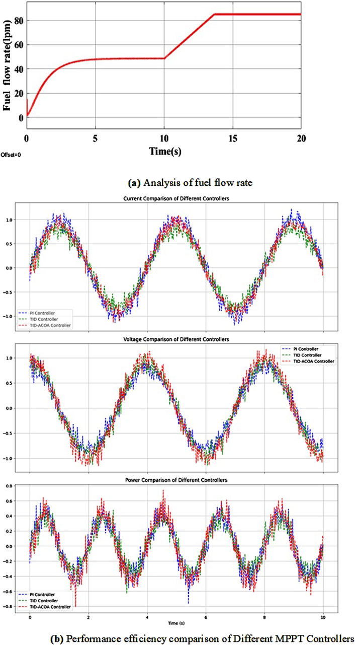
Figure 15. (A) analysis of fuel flow rate. (B) performance efficiency comparison of different MPPT controllers.
Efficiency of the proposed method is 0.036% higher than the TID-COA method, 0.218% superior to the TID controller, and 0.173% higher than the PI controller. Settling time of the proposed system is 0.028 s and also produces less oscillation. Similarly, when the fuel flow rate is 85 lpm, the output current, output voltage and output power of the proposed method is 30 A, 200 V and 6000 W respectively, which is same as the 50 lpm fuel flow rate. Efficiency of the proposed system is 99.89%, which is higher than other conventional methods. The settling time of the proposed methods is 0.0193, which is 98.87% less than the TID-COA method, 99.59% less than the TID controller, and 99.39% less than the PI method and also the proposed method has less oscillation than the conventional methods.
From Table 1 comparative analysis, it is found that the proposed TID-ACOA method has less oscillations, high output power, high efficiency and low settling time than the conventional methods, such as PI, TID and TID-COA.
Figure 15B depicts the performance comparison of different MPPT controllers, including PI, TID, and TID-ACOA. The figure illustrates three key metrics: current, voltage, and power. The top graph shows the current output for each controller over time, highlighting their respective tracking abilities. The middle graph compares the voltage levels achieved by each controller, providing insight into their effectiveness in maintaining stable voltage. The bottom graph presents the power output, demonstrating how well each controller maximizes power extraction from the fuel cell system. This comprehensive comparison showcases the efficiency of the TID-ACOA MPPT controller relative to other conventional controllers in optimizing fuel cell performance.
Table 2 depicts a comprehensive comparison of the proposed TID-ACOA MPPT controller against conventional methods. The Tracking Time (ms) column illustrates the duration each controller takes to achieve the maximum power point (MPP), showcasing the efficiency of the TID-ACOA MPPT controller in minimizing this time. The Maximum Power Point (MPP) Efficiency (%) indicates the percentage of maximum power extracted from the fuel cell stack, with the TID-ACOA MPPT controller demonstrating superior efficiency. The Converter Voltage Settling Time (ms) measures how quickly the boost converter output voltage stabilizes after reaching the MPP, with the TID-ACOA MPPT controller exhibiting a reduced settling time. Oscillations Around MPP provides a qualitative assessment of fluctuations around the MPP, where “High” reflects more fluctuations and “Very Low” denotes minimal fluctuations; the TID-ACOA MPPT controller shows fewer oscillations. Lastly, Voltage Ripple (%) quantifies the voltage fluctuation around the MPP as a percentage, highlighting the minimal ripple achieved by the TID-ACOA MPPT controller. Overall, the table underscores the TID-ACOA MPPT controller’s superior performance in tracking time and efficiency compared to traditional methods.
Table 3 depicts a comparative performance analysis of various MPPT controllers applied to fuel cell systems, highlighting the effectiveness of the proposed TID-ACOA controller. The TID-ACOA controller achieves the highest MPPT efficiency at 98.6%, outperforming other controllers like the PI controller at 93.2% and even advanced algorithms like PSO and GA, which achieve 97.1% and 97.3%, respectively. Additionally, the TID-ACOA demonstrates the fastest tracking speed of 8.5 m, significantly quicker than the TID-COA’s 9.7 m and the COA’s 11.4 m. Voltage settling time is also minimized to 7.2 m with the TID-ACOA, compared to 7.9 m with TID-COA and 10.8 m with the TID controller. Furthermore, the TID-ACOA reduces oscillations to just 0.02 V, offering greater stability compared to other methods, such as the COA with 0.07 V. Lastly, the TID-ACOA controller achieves the highest converter voltage at 57.9 V, demonstrating its superior ability to enhance low output voltages from the fuel stack. This comprehensive evaluation underscores the TID-ACOA’s superior performance across all critical metrics.
5.5 Comparison with variable fuel flow rate
Tables 4, 5 depict a comparative analysis of different MPPT controllers—PI, TID, TID-COA, and the proposed TID-ACOA—evaluated at two different fuel flow rates: 50 L per minute (lpm) and 85 lpm. The analysis includes critical performance metrics such as current and voltage of input, power of input, settling time (V_out), current and voltage of output, power of output, efficiency, and oscillations. In both scenarios, the proposed TID-ACOA controller consistently outperforms the other controllers. At a fuel flow rate of 50 lpm (Table 4), the proposed controller achieves the fastest settling time of 0.028 s, significantly quicker than the PI and TID controllers, which exhibit higher settling times of 3.2 and 4.3 s, respectively. The proposed controller also demonstrates superior efficiency, reaching 100%, while the PI and TID controllers achieve slightly lower efficiencies of 99.82% and 99.78%, respectively. Additionally, the proposed controller shows minimal oscillations, contributing to the stability and reliability of the system. Similarly, at a fuel flow rate of 85 lpm (Table 5), the proposed TID-ACOA controller again exhibits the fastest settling time of 0.0193 s, outperforming the PI and TID controllers, which have settling times of 3.18 and 3.175 s, respectively. The proposed controller maintains high efficiency at 100% and shows minimal oscillations, indicating its ability to maintain stable operation even under varying conditions.
6 Conclusion
PEMFCs offer several advantages including high power density, compact size, efficient power conversion, quick startup, and lightweight construction. In this study, a PEMFC-based TID-ACOA controller is proposed and compared against conventional PI, TID, and TID-COA controllers. The performance of these methods were assessed across varying fuel flow rates to analyze system dynamics in terms of current, voltage, power output, efficiency, settling time, and oscillations. The PEMFC-based TID-ACOA controller demonstrated superior efficiency improvements compared to other methods, achieving a 0.036% increase over TID-COA, 0.218% over TID, and 0.173% over PI methods at a fuel flow rate of 50 lpm. At 85 lpm, the proposed method achieved an efficiency of 99.808%, outperforming conventional methods. Simulation results confirm that the TID-ACOA controller exhibits robust performance across different fuel flow conditions. Additionally, the study utilized a conventional boost converter to enhance the fuel stack’s output voltage, leveraging benefits, such as simplicity in design, cost-effectiveness, and operational flexibility. In future, advanced AI techniques will be used to further improve the applicability of the proposed system in real time.
Data availability statement
The original contributions presented in the study are included in the article/supplementary material, further inquiries can be directed to the corresponding author.
Author contributions
GS Conceptualization, Data curation, Formal Analysis, Methodology, Software, Validation, Writing–original draft. CK Conceptualization, Methodology, Project administration, Resources, Software, Supervision, Validation, Visualization, Writing–original draft. FA: Formal Analysis, Funding acquisition, Investigation, Validation, Visualization, Writing–review and editing.
Funding
The author(s) declare that financial support was received for the research, authorship, and/or publication of this article. This work was supported by the Researchers Supporting Project number (RSPD 2024R646), King Saud University, Riyadh, Saudi Arabia.
Conflict of interest
The authors declare that the research was conducted in the absence of any commercial or financial relationships that could be construed as a potential conflict of interest.
Publisher’s note
All claims expressed in this article are solely those of the authors and do not necessarily represent those of their affiliated organizations, or those of the publisher, the editors and the reviewers. Any product that may be evaluated in this article, or claim that may be made by its manufacturer, is not guaranteed or endorsed by the publisher.
References
Akter, F., Roy, T. K., Islam, M. S., Alkhateeb, A. hameed F., and Mollah, Md A. (2022). Design of a nonlinear integral terminal sliding mode controller for a pem fuel cell based on a dc-dc boost converter. IEEE Access 10, 97419–97428. doi:10.1109/access.2022.3205733
Alcazar, Y. J. A., Bascope, R. T., de Oliveira, D. S., Andrade, E. H., and Cardenas, W. G. (2008). “High voltage gain boost converter based on three-state switching cell and voltage multipliers,” in Proc 34th annual conf IEEE ind electron (IECON), 2346e52.
Babu, C., and Ponnambalam, P. (2018). The theoretical performance evaluation of hybrid PV-TEG system. Energy Convers. Manag. 173, 450–460. doi:10.1016/j.enconman.2018.07.104
Bayat, P., and Baghramian, A. (2020). A novel self-tuning type-2 fuzzy maximum power point tracking technique for efficiency enhancement of fuel cell based battery chargers. Int. J. Hydrogen Energy 45 (43), 23275–23293. doi:10.1016/j.ijhydene.2020.05.274
Dehghani, M., ZeinabMontazeri, E. T., Trojovský, P., and Trojovský, P. (2023). Coati Optimization Algorithm: a new bio-inspired metaheuristic algorithm for solving optimization problems. Knowledge-Based Syst. 259, 110011. doi:10.1016/j.knosys.2022.110011
Elkasem, A. H. A., Kamel, S., Mohamed, K., ErsanKabalc, I., and Shahinzadeh, H. (2022). “Frequency stability enhancement of hybrid multi-area power grid considering high renewable energy penetration using TID controller,” in 2022 4th global power, energy and communication conference (GPECOM) (IEEE), 322–327.
Haroun, R., El Aroudi, A., Cid-Pastor, A., and Martinez-Salamero, L. (2014). “Sliding mode control of output-parallel-connected two-stage boost converters for PV systems,” in Proc 11th int multi-confsyst signals devices (SSD), 1e6.
Harrag, A., and Rezk, H. (2021). Indirect P&O type-2 fuzzy-based adaptive step MPPT for proton exchange membrane fuel cell. Neural Comput. Appl. 33, 9649–9662. doi:10.1007/s00521-021-05729-w
Hsieh, Y.-P., Chen, J.-F., Liang, T.-J., and Yang, L.-S. (2011). A novel high step up DC_ DC converter for a microgrid system. IEEE Trans. Power Electron 26 (4), 1127e36. doi:10.1109/TPEL.2010.2096826
HussaianBasha, C., Murali, M., Rafikiran, S., Mariprasath, T., and Bhaskara Reddy, M. (2022). An improved differential evolution optimization controller for enhancing the performance of PEM fuel cell powered electric vehicle system. Mater. Today Proc. 52, 308–314. doi:10.1016/j.matpr.2021.09.011
Hwang, J. J., Hu, J. S., and Lin, C. H. (2015). Design of a range extension strategy for power decentralized fuel cell/battery electric vehicles. Int. J. Hydrogen Energy 40 (35), 11704–11712. doi:10.1016/j.ijhydene.2015.04.026
Inci, M., and Caliskan, A. (2020). Performance enhancement of energy extraction capability for fuel cell implementations with improved Cuckoo search algorithm. Int. J. Hydrogen Energy 45 (19), 11309–11320. doi:10.1016/j.ijhydene.2020.02.069
Kart, S., Demir, F., Kocaarslan, I., and Genc, N. (2024). Increasing PEM fuel cell performance via fuzzy-logic controlled cascaded DC-DC boost converter. Int. J. Hydrogen Energy 54, 84–95. doi:10.1016/j.ijhydene.2023.05.130
Khalil, H., Elshazly, O., and Omar, S. (2024). Optimal fuzzy pre compensated TID controller for nonlinear dynamical systems. Menoufia J. Electron. Eng. Res. 0, 1–8. doi:10.21608/mjeer.2024.242642.1084
Krishnamurthy, K., Padmanaban, S., Blaabjerg, F., Neelakandan, R. B., and Prabhu, K. R. (2019). Power electronic converter configurations integration with hybrid energy sources A comprehensive review for state-of the-art in research. Electr. Power Components Syst. 47 (18), 1623–1650. doi:10.1080/15325008.2019.1689457
Kumar, K., Babu, N. R., and Prabhu, K. R. (2017). Design and analysis of an integrated cuk-SEPIC converter with MPPT for standalone wind/PV hybrid system. Int. J. Renew. Energy Resour. 7 (1), 96e106. doi:10.20508/ijrer.v7i1.5078.g6969
Kumar, K., Tiwari, R., VenkataVaraprasad, C. B., Jyotheeswara Reddy, K., and Reddy, K. J. (2021). Performance evaluation of fuel cell fed electric vehicle system with reconfigured quadratic boost converter. Int. J. Hydrogen Energy 46 (11), 8167–8178. doi:10.1016/j.ijhydene.2020.11.272
Li, W., Zhao, Y., Wu, J., and He, X. (2012). Interleaved high step-up converter with winding-cross-coupled inductors and voltage multiplier cells. IEEE Trans. Power Electron 27 (1), 133–143. doi:10.1109/tpel.2009.2028688
Liu, X., Krishna, R., Amgad, E., Henning, L.-B., Wang, M., and Neha, R. (2020). Comparison of well-to-wheels energy use and emissions of a hydrogen fuel cell electric vehicle relative to a conventional gasoline powered internal combustion engine vehicle. Int. J. Hydrogen Energy 45 (1), 972e8. doi:10.1016/j.ijhydene.2019.10.192
Mayo-Maldonado, J. C., Valdez-Resendiz, J. E., Sanchez, V. M., Rosas- Caro, J. C., Claudio-Sanchez, A., and Puc, F. C. (2019). A novel PEMFC power conditioning system based on the interleaved high gain boost converter. Int. J. Hydrogen Energy 44 (24), 12508–12514. doi:10.1016/j.ijhydene.2018.11.090
Ozbay, F. A., and Alatas, B. (2021). Adaptive Salp swarm optimization algorithms with inertia weights for novel fake news detection model in online social media. Multimedia Tools Appl. 80 (26), 34333–34357. doi:10.1007/s11042-021-11006-8
Rafikiran, S., Devadasu, G., Hussaian Basha, C. H., Mary Tom, P., Prashanth, V., Dhanamjayulu, C., et al. (2023). Design and performance analysis of hybrid MPPT controllers for fuel cell fed DC-DC converter systems. Energy Rep. 9, 5826–5842. doi:10.1016/j.egyr.2023.05.030
Rajput, G. K., Yadav, A., Kumar, A., Gautam, A., Tiwari, A., Babu, N. R., et al. (2020). Design of TID controller based on firefly algorithm for controlling the speed of a DC Motor. E3S Web Conf., doi:10.1051/e3sconf/202018401038
Reddy, K. J., and Natarajan, S. (2018). Energy sources and multi-input DCDC converters used in hybrid electric vehicle applications A review. Int. J. Hydrogen Energy 43 (36), 17387e408, doi:10.1016/j.ijhydene.2018.07.076
Rezk, H., Aly, M., and Ahmed, F. (2021). A novel strategy based on recent equilibrium optimizer to enhance the performance of PEM fuel cell system through optimized fuzzy logic MPPT. Energy 234, 121267. doi:10.1016/j.energy.2021.121267
Rosas-Caro, J. C., M Sanchez, V., Valdez-Resendiz, J. E., Mayo- Maldonado, J. C., Beltran-Carbajal, F., and Valderrabano-Gonzalez, A. (2017). Quadratic buck boost converter with positive output voltage and continuous input current for PEMFC systems. Int. J. Hydrogen Energy 42 (51), 30400–30406. doi:10.1016/j.ijhydene.2017.10.079
Shahin, A., Hinaje, M., Martin, J.-P., Pierfederici, S., Ra€el, S., and Davat, B. (2010b). High voltage ratio DC_DC converter for fuel-cell applications. IEEE Trans. Ind. Electron 57 (12), 3944e55. doi:10.1109/TIE.2010.2045996
Shahin, A., Huang, B., Martin, J. P., Pierfederici, S., and Davat, B. (2010a). New nonlinear control strategy for non-isolated DC/DC converter with high voltage ratio. Energy Convers. Manag. 51 (1), 56–63. doi:10.1016/j.enconman.2009.08.032
Singh, S., Manna, S., Mansoori, M. I. H., and Akella, A. K. (2020). “Implementation of perturb & observe MPPT technique using boost converter in PV system,” in 2020 international conference on computational intelligence for smart power system and sustainable energy (CISPSSE) (IEEE), 1–4.
Srinivasan, S., Tiwari, R., Krishnamoorthy, M., Padma Lalitha, M., and Kalyan Raj, K. (2021). Neural network based MPPT control with reconfigured quadratic boost converter for fuel cell application. Int. J. Hydrogen Energy 46 (9), 6709–6719. doi:10.1016/j.ijhydene.2020.11.121
Tiwari, R., and Babu, N. R. (2016a). Recent developments of control strategies for wind energy conversion system. Renew. Sustain. Energy Rev. 66, 268–285. doi:10.1016/j.rser.2016.08.005
Tiwari, R., and Babu, N. R. (2016b). Fuzzy logic based MPPT for permanent magnet synchronous generator in wind energy conversion system. IFAC-Papers Online 49 (1), 462–467. doi:10.1016/j.ifacol.2016.03.097
Tiwari, R., and Babu, N. R. (2017). Comparative analysis of pitch angle controller strategies for PMSG based wind energy conversion system. Int. J. Intelligent Syst. 9 (5), 62e73. doi:10.5815/ijisa.2017.05.08
Tiwari, R., Krishnamurthy, K., Neelakandan, R., Padmanaban, S., and Wheeler, P. (2018). Neural network based maximum power point tracking control with quadratic boost converter for PMSGd wind energy conversion system. Electron (Bruss) 7 (2), 1e17. doi:10.3390/electronics7020020
Tofoli, F. L., de Souza Oliveira, D., Torrico-Bascope, R. P., and Alcazar, Y. J. A. (2012). Novel non isolated high-voltage gain DC_DC converters based on 3SSC and VMC. IEEE Trans. Power Electron 27 (9), 3897e907. doi:10.1109/TPEL.2012.2190943
Touti, E., Aoudia, M., Hussaian Basha, C. H., and Alrougy, I. M. (2024). A novel design and analysis adaptive hybrid ANFIS MPPT controller for PEMFC-fed EV systems. Int. Trans. Electr. Energy Syst. 2024, 1–17. doi:10.1155/2024/5541124
Xiong, H., Liu, H., Zhang, R., Yu, L., Zong, Z., Zhang, M., et al. (2019). An energy matching method for battery electric vehicle and hydrogen fuel cell vehicle based on source energy consumption rate. Int. J. Hydrogen Energy 44 (56), 29733–29742. doi:10.1016/j.ijhydene.2019.02.169
Nomenclature
MPPT Maximum Power Point Tracking
TID Tilt Integral Derivative
ACOA Adaptive Coati Optimization Algorithm
PID Proportional Integral Derivative
PV Photo Voltaic
FC Fuel Cell
P&O Perturb and Observer
NN Neural Network
IC Incremental Conductance
PSO Particle Swarm Optimization
PI Proportional Integral
MF Membership Function
AAS Adaptive Adjustable Step
VSV-based RBFC Variable Step Value-Radial Basis Functions Controllers
VP&O Variable P&O
VSGWA Variable Step Gray Wolf Algorithm
ANFIS Adaptive Neuro Fuzzy Inference Systems
EIC Enhanced Increment Conductance
FLC Fuzzy Logic Controllers
IHC Improved Hill Climbing
EDE Enhanced Differential Evolutionary
MPO Marine Predators Optimization
RBFN Radial Basis Functions Networks
WECS Wind Energy Conversion Systems
EV Electric Vehicle
BLDC Brushless DC
EIWO Elitist Invasive Weed Optimization
ITSMC Integral Terminal Sliding Mode Controller
EO Equilibrium Optimizer
ECPO Electric Charged Particles Optimization
SHO Spotted Hyena Optimizer
ANN Artificial Neural Network
IGBT Insulated-Gate Bipolar Transistor
FOC Fractional Order Controller
FOIC Fractional Order Incremental Conductance
Keywords: maximum power point extraction, fuel stack, optimization, TID controller, boost DC-DC converter
Citation: Subramaniam G, Kumar C and Alsaif F (2024) Performance evaluation of fuel cell based on a DC-DC boost converter through optimized MPPT controller. Front. Energy Res. 12:1461634. doi: 10.3389/fenrg.2024.1461634
Received: 08 July 2024; Accepted: 20 September 2024;
Published: 07 October 2024.
Edited by:
Peiwen Li, University of Arizona, United StatesReviewed by:
Dheeraj Joshi, Delhi Technological University, IndiaRenyou Xie, University of New South Wales, Australia
Copyright © 2024 Subramaniam, Kumar and Alsaif. This is an open-access article distributed under the terms of the Creative Commons Attribution License (CC BY). The use, distribution or reproduction in other forums is permitted, provided the original author(s) and the copyright owner(s) are credited and that the original publication in this journal is cited, in accordance with accepted academic practice. No use, distribution or reproduction is permitted which does not comply with these terms.
*Correspondence: C. Kumar, Y2t1bWFybWU4MUBnbWFpbC5jb20=
 G. Subramaniam
 C. Kumar
 Faisal Alsaif