 Shiming Xu1,2
 Bo Yu
Bo Yu
94% of researchers rate our articles as excellent or good
Learn more about the work of our research integrity team to safeguard the quality of each article we publish.
Find out more
ORIGINAL RESEARCH article
Front. Energy Res., 05 September 2024
Sec. Energy Efficiency
Volume 12 - 2024 | https://doi.org/10.3389/fenrg.2024.1448416
This article is part of the Research TopicEnergy Management, Energy Efficiency Policies, and Energy System StudiesView all 7 articles
Currently, there is a scarcity of studies exploring the safe operating parameters for coal-fired power units at loads below 30%.To accurately understand the operating characteristics of coal-fired units under low load conditions, and to provide a design basis for flexibility modifications, a simulation model coupled with boiler and turbine was established, which includes the flue gas and air system, steam and water system, steam turbine, and steam extraction heat recovery system, and the iterative calculation strategy for low load conditions was proposed. The simulation calculation was performed on a 350 MW supercritical coal-fired unit, with the model results showing a high degree of alignment with the unit’s design and operational parameters. Under the condition of 269MW, the maximum calculation error between the model’s predicted exit flue gas temperature of the air preheater and the actual operational results was 8.84%. This discrepancy was due to a sudden increase in the operating flue gas temperature, which may be associated with a blockage in the air preheater. And the simulation results under low load conditions indicate that when the unit load is below 20%, the furnace total airflow is controlled to no less than 30% of the airflow at Maximum Continuous Rating (BMCR) and the minimum feedwater flow rate can be reduced to 20% of that in Turbine Heat Acceptance (THA) load, and the unit switches to wet state operation around 20% load. As the unit load decreases, the coal consumption rate for power generation and steam turbine heat consumption rate both increase significantly. The coal consumption rate for power generation at 30% load is increased by 13.3% compared to BMCR load, and it is increased by 32.5% at 15% load which is operated in wet state. Under low load conditions, the coal consumption rate of the unit can be reduced by decreasing the oxygen content in the flue gas, reducing the minimum feedwater flow rate, and implementing boiler water recirculation.
Green, safe, and energy-efficient practices are parallel requirements on the path to energy transition, with fossil fuels providing a secure and economical foundation for this shift. In the context of carbon peaking and carbon neutrality goals, China’s low-carbon transition in the energy and power sectors has accelerated, with new energy sources such as wind and solar power gradually becoming the primary sources of incremental electricity generation. Traditional coal-fired power’s role in the power system is shifting from a baseload power source to a regulating power source, with flexibility enhancement becoming a key direction for coal-fired power transformation (Xu et al., 2023). Significant load variations and the realizable ability to operate at ultra-low loads are crucial goals for enhancing the flexibility of coal-fired power units. According to statistics, during the 13th Five-Year Plan period, 90 million kilowatts of flexible transformation were completed, with a batch of pure condensing units and heating units achieving minimum technical output levels of 30%–35% and 40%–50% of rated capacity, respectively. Some units have achieved short-cycle operation at 10%–15% of rated load (Pan et al., 2020).
Coal-fired power units in China are generally designed to operate at rated load, which results in significant deviations from design conditions when operating at ultra-low loads, leading to noticeable declines in the economic performance of the unit. Currently, the minimum design load for boilers is typically around 30%, and when operating below this threshold, the furnace-side feed coal, airflow, and feedwater volumes deviate from the original air-coal ratio and water-coal ratio curves (Wang et al., 2023). On the turbine side, parameters such as main reheat steam temperature and cylinder efficiency exhibit substantial uncertainty, posing significant challenges for the flexibility retrofit of the unit. Pre-compliance testing is an effective method for determining operating parameters under low-load conditions. For instance, Wang et al. through deep peak-shaving experiments, analyzed temperature changes inside the furnace, variations in SCR denitrification system inlet temperature, and key parameters during wet state operation at 20% load (Wang, 2022). However, Pre-Compliance testing carries inherent safety risks.
Currently, research at low loads predominantly concentrates on issues of combustion safety in boilers. Numerous studies use Computational Fluid Dynamics (CFD) methods to simulate the combustion scenarios within coal-fired boilers under reduced load conditions (Chang et al., 2021; Li et al., 2021; Ma et al., 2023). Additionally, there are investigations that utilize numerical modeling to replicate the operating conditions within the furnace. However, these typically concentrate on load levels exceeding 30%, neglecting a comprehensive examination of the unit’s operational parameters at even lower loads (Klaus, 2006; Jens et al., 2017). Research on the progress of simulation models for coal-fired power units has been summarized (Alobaid et al., 2017), and the existing modeling methods for transient processes in coal-fired power generation units, as well as the current research status of operational flexibility in transient processes, have been reviewed (Zhao et al., 2023). Traditional dynamic simulation methods include fuzzy neural network methods and genetic algorithms. In recent years, researchers have adopted software such as GSE and APROS to model the thermal systems of coal-fired power units, resulting in significant improvements in simulation accuracy and speed (Ralf et al., 2015).
A typical process during low-load operation of a boiler is the transition from dry to wet operation, which involves three stages: dry operation, dry/wet transition, and wet operation (Wang et al., 2022). Significant differences exist in the control methods and operational parameters of boilers during dry and wet operations. In once-through boilers, during the process of load reduction, the operation mode of the boiler transitions from dry to wet, which reduces the heat absorption by the water-cooled walls in the furnace. This transition is beneficial for stable combustion and helps maintain the appropriate flue gas temperature at the denitration inlet (Zhang, 2018). In terms of wet process simulation analysis, the characteristics of wet operation for once-through boilers were studied, and a comparison was made between the economic feasibility of two high-energy hydrothermal mass recovery technology schemes (Shi et al., 2010). However, the model did not account for changes in the furnace-side parameters.
In many simulation studies, wet operation is often classified as part of the unit startup process. A model for direct-fired power generation units capable of simulating a wide range of operating processes was developed, including both dry and wet operations (Ralf et al., 2015). A startup model was established using APROS and Aspen Plus Dynamics for power generation units, analyzing the dynamic characteristics of boiler wet operation during the startup process (Deng et al., 2017; Ata et al., 2020). The process of load reduction to the stable wet operation of boilers differs significantly from boiler startup, with parameters such as the transition point from dry to wet operation and the optimal main and reheat steam temperatures during wet operation requiring further clarification. There is also a lack of comprehensive research describing the complete impact of wet operation on boilers.
This study employs a coupled calculation model of boiler and turbine to conduct simulation calculations for unit operation at low loads which analyzes the transition point from dry to wet operation of the boiler under constraints of minimum airflow and minimum feedwater flow, and determines the main thermodynamic parameters and economic viability of the boiler and turbine sides during wet operation. The simulation method proposed in this study will provide crucial insights into the flexibility retrofitting of coal-fired units and the design of novel units.
The modeling is conducted for a 350 MW supercritical unit. Boiler-side parameters include 25.4 MPa pressure/574°C/572°C. The boiler operates under supercritical pressure with a spiral coil furnace, featuring a single furnace chamber, primary and intermediate reheat, balanced ventilation, solid slag discharge, a full steel suspension structure, and a tower-type design. The superheater adopts a three-stage layout, while the reheater adopts a two-stage layout. Along the flue gas path in the upper part of the furnace, there are sequentially arranged primary superheater, tertiary superheater, secondary reheater, partitioned flue gas passage heating surface, and economizer. A flue gas temperature regulating baffle is installed at the top of the furnace to distribute the flue gas volume, controlling the outlet temperature of the reheated steam. The flue gas, after passing through the baffle adjustment, is directed through the rear flue to the SCR reactor, beneath which graded economizers are installed. The pulverized coal system utilizes a positive pressure cold primary air direct injection system, equipped with six medium-speed coal mills, corresponding to six layers of once-through burners.
The steam turbine is a highly efficient supercritical, single-reheat, single-shaft, three-cylinder, double-exhaust, condensing steam turbine unit, equipped with eight stages of non-regulating steam extraction. The high-pressure heater drain system employs a stepwise gravity drainage method, where the drainage flows from the heater at a higher pressure to the one at a lower pressure, eventually being discharged into the deaerator. The low-pressure heaters also utilize a sequential gravity drainage method, with the final discharge into the condenser, where it enters the condensate system.
When operating the boiler at below 30% load, there are no corresponding design parameters available as operational guidelines. Thus, it is necessary to establish a new coupled thermodynamic balance calculation model for both the boiler and turbine sides, as illustrated in Figure 1. This model encompasses the entire thermal system of the plant, including the boiler flue gas system, steam-water system, turbine power generation, extraction and reheat system, and other components.

Figure 1. Coupled calculation model of boiler and turbine.
In the heat exchange calculation on the furnace side, the challenge lies in determining the heat transfer coefficients of various heat exchange modules under different loads (Zhao et al., 2019). The standard of JB/T 8659–1997 introduces the convective heat transfer coefficients of gas, as well as water under different operating conditions. The convective heat transfer coefficients on the flue gas side are calculated using the empirical formula (Yang et al., 1998):
In the equation,
For the primary superheater, tertiary superheater, secondary reheater, and other heat exchangers, the influence of radiative heat transfer on the flue gas side needs to be considered. The flue gas side heat transfer coefficient can be simplified as the sum of the convective heat transfer coefficient and radiative heat transfer coefficient, without considering ash fouling thermal resistance.
From the inlet header to the outlet header of the water-cooled wall, spiral coils with low mass flow rates are employed throughout, utilizing light tubes with dimensions of Φ38 × 7.3 mm. The tube material is 15CrMoG, with a pitch of 53 mm. The convective heat transfer coefficient inside the spiral coil under supercritical pressure is calculated using the empirical formula (Yang et al., 1998):
In the equation, a2 represents the convective heat transfer coefficient on the working fluid side, with units of W·m-2·K−1; G denotes the mass flow rate of the working fluid, in kg·m-2·s-1; D is the equivalent inner diameter of the tube, in meters (m); H signifies the enthalpy of the working fluid, in J·kg-1; ρ stands for the density of the working fluid, in kg·m-3; λ represents the thermal conductivity of the working fluid, in W·m-1·K−1; T denotes the temperature, in Kelvin (K); u is the dynamic viscosity, in Pa·s. The subscript f indicates the working fluid temperature as the qualitative temperature, while the subscript w indicates the inner wall temperature of the tube as the qualitative temperature. θ represents the helix angle. The coefficient η is determined from the reference literature (Yong et al., 2022).
The convective heat transfer coefficient of subcooled water flowing inside helical light tubes under subcritical pressure is given by the following equation (Yang et al., 1998):
In the equation, Cp represents the specific heat capacity at a constant pressure of the working fluid, in J·kg-1·K−1. The correction factor for the helix angle can be determined by referring to a chart or performing linear interpolation.
In the upper furnace, vertical light tubes with a diameter of Φ38 × 6.2/7.5/8 mm and a pitch of 57.5/115 mm are selected, using 12Cr1MoVG tube material. The convective heat transfer coefficient of supercritical water in vertical upward light tubes under non-heat deterioration conditions is calculated using Equation (Yang et al., 1998):
The calculation formula for the power generation of a steam turbine generator unit is as follows:
In the equation,
During low-load operation, adjustments to the coal supply, primary and secondary air flow rates, flue gas baffle opening, and desuperheating water flow are required on the boiler side to achieve an appropriate main and reheat steam temperature. Meanwhile, on the turbine side, it is necessary to verify the corresponding feedwater temperature and power generation corresponding to the main and reheat steam temperature. Both processes require iterative calculation, as depicted in Figure 2.
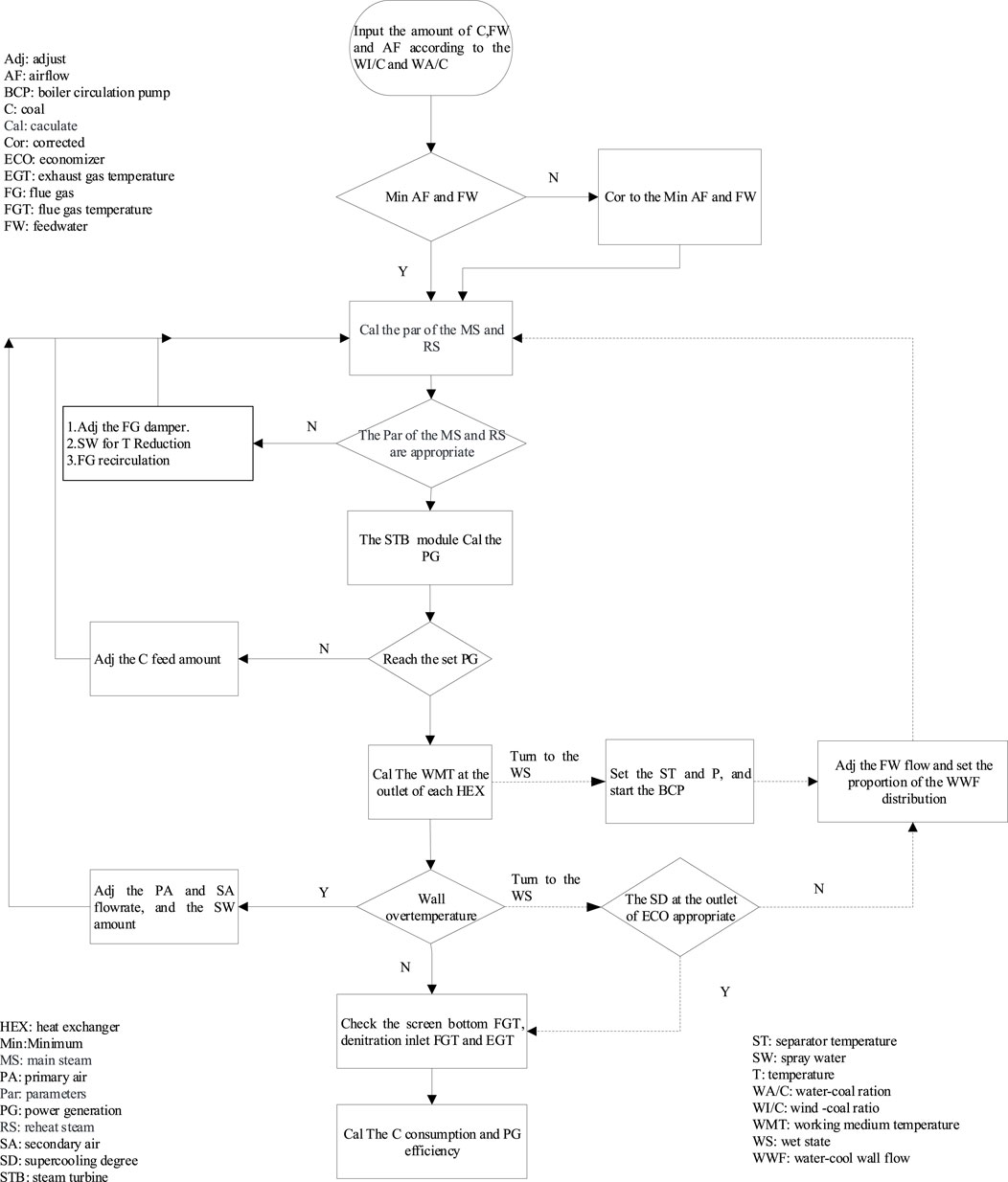
Figure 2. Coupled calculation flowchart of boiler-turbine system.
In the simulation calculations, it is assumed that the fuel burns completely without considering the impact of wall ash on heat transfer. The primary constraints include minimum air flow requirements, minimum water flow rate restrictions, and the oversaturation constraint at the economizer outlet. These constraints are all derived from the boiler operating procedures.
Based on Formulas 1–5, the heat transfer coefficients of various modules under typical loads are calculated and used as input parameters for each module. The results are shown in Figure 3, where the variation curve of heat transfer coefficients with load closely matches the thermal design parameters of the boiler. The first-stage superheater is subjected to both convective and radiative heating on the flue gas side, while the radiative heat transfer on the flue gas side of the second-stage superheater can be neglected. The heat transfer coefficient of the first-stage superheater is significantly greater than that of the second-stage superheater and gradually decreases with decreasing load.
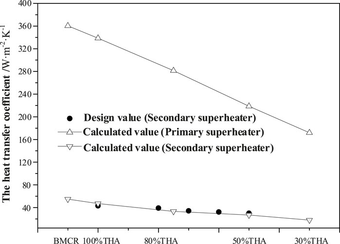
Figure 3. Variation curve of heat transfer coefficients with load.
The designed coal for combustion is Shenhua bituminous coal, The actual coal utilized comprises a blend of bituminous coal and lean coal, with industrial and elemental analyses presented in Table 1.
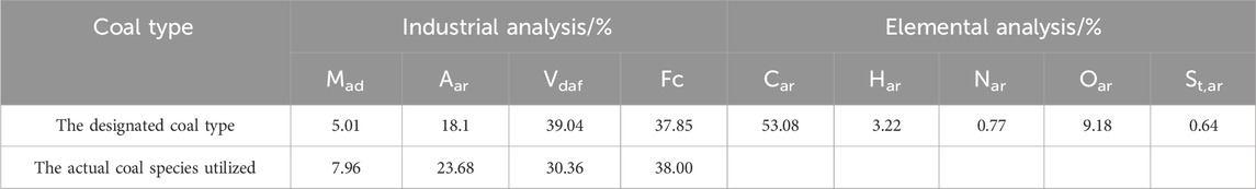
Table 1. Different cases for analysis.
Using the BMCR condition as the model calculation design condition, and 100% THA, 75% THA, 50% THA, and 30% THA as the verification conditions, the flue gas temperature distribution at different heat exchange modules inside the furnace is calculated for each load. A comparison with the boiler thermal design parameters is presented in Figure 4. It can be observed that the furnace flue gas temperature gradually decreases with decreasing load. By adjusting the heat transfer coefficients at each load, the calculated flue gas temperature values are in basic agreement with the design parameters, with a maximum deviation of 5.3% in maximum flue gas temperature.
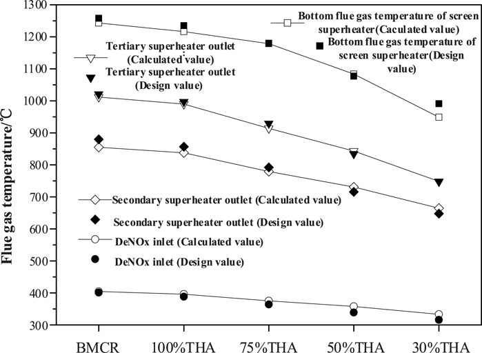
Figure 4. Comparison of smoke temperature distribution under different operating conditions.
The temperature distribution of the working medium on the steam side under various loads is illustrated in Figure 5. From 100% to 30% of the Total Heating Area (THA) operating conditions, a constant-sliding pressure operation mode is adopted. The set main and reheat steam temperatures are achieved by adjusting the flue gas damper and reducing the flow rate of the warm water. The calculated values of the outlet working medium temperatures of the economizer and water-cooled wall match the design values, with a maximum deviation of 3.63%. A comparison between the calculated and design temperatures of the flue gas and steam under the verification conditions indicates that the computational model accurately simulates the operational characteristics of the boiler and steam turbine under different loads.
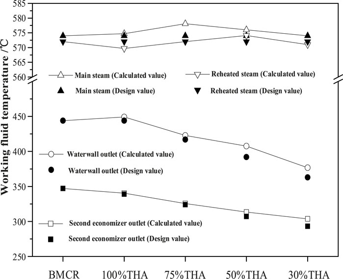
Figure 5. Comparison of temperature distribution of working medium under different working conditions.
Further, utilizing a boiler-turbine coupling model, the distribution of flue gas temperature and working medium temperature under actual coal combustion conditions in the boiler was calculated and compared with the actual operational parameters of the unit. The inlet flue gas temperature for denitrification and the outlet flue gas temperature of the air preheater were computed for load conditions of 304 MW, 269 MW, 219 MW, and 119 MW, as shown in Figure 6. It can be observed that the calculated values of the inlet flue gas temperature for denitrification and the outlet flue gas temperature of the air preheater at all four loads are in good agreement with the operational values of the unit, with a maximum deviation of 8.84%. However, at 269 MW, an anomalous increase in the operational value of the outlet flue gas temperature of the air preheater was observed, which may be related to blockage occurring in the air preheater of the unit.
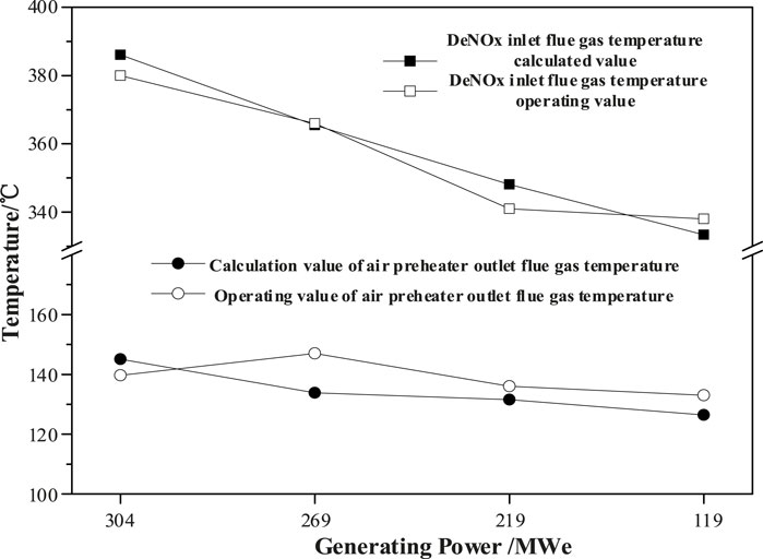
Figure 6. Comparison of simulated and operational values of inlet flue gas temperature for denitrification and outlet flue gas temperature of the air preheater at various loads.
The intermediate point temperature and the exit temperature of the second economizer were calculated under load conditions of 304 MW, 269 MW, 219 MW, and 119 MW, as shown in Figure 7. It can be observed that with decreasing load, both the intermediate point temperature and the exit temperature of the second economizer decrease. The calculated values of the working medium temperatures at these two locations are in good agreement with the operational values, with a maximum calculated error on the working medium side of 5.71%.
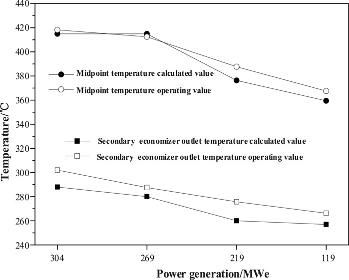
Figure 7. Comparison of simulated and operational values of intermediate point temperature and economizer outlet temperature at various loads.
Under actual operating conditions of the unit, the heat transfer coefficient deviates from the design conditions due to fouling on the heating surfaces, resulting in simulation errors greater than those under design conditions. However, for engineering design purposes, these differences remain acceptable. Currently, the unit can only operate at loads above 30%. To understand the operational characteristics at loads below 30%, it is necessary to conduct simulation calculations for low-load operations.
When the boiler operates at low loads, the traditional water-coal ratio and air-coal ratio curves become imbalanced. Limited by the boiler blowing and induced draft fan blade openings, the furnace needs to maintain a minimum air volume at low loads (Zhang et al., 2017), ensuring that the furnace air volume remains no less than 30% of the BMCR air volume. Additionally, considering the requirements for the hydraulic safety of the boiler water-cooled wall and the safety of the heating surface, it is essential to maintain the subcooling at the outlet of the economizer and prevent overheating of the water-cooled wall. The boiler feedwater flow rate cannot be continuously reduced, there exists a minimum feedwater flow rate, typically around 30% of the rated feedwater flow rate (Sun et al., 2022), and this value is closely related to the unit’s characteristics.
The calculation of feedwater flow and air flow under different loads is conducted according to the water-coal ratio and air-coal ratio curves, as illustrated in Figure 8. When the unit load is below 20%, the total airflow in the furnace will be less than 30% of the BMCR airflow. At this point, the operation should be switched to minimum airflow mode, wherein the airflow remains constant as the load continues to decrease. When the minimum feedwater flow is set at 30% of the rated feedwater flow, the corresponding unit load is approximately 30%. This indicates that the feedwater flow remains at the minimum flow rate when the unit load is below 30%. Theoretically, as the minimum flow rate increases, the transition point from dry to wet operation also advances accordingly. To enhance the economic efficiency at low loads, efforts should be made to minimize the minimum flow rate, thereby delaying the transition to wet operation.
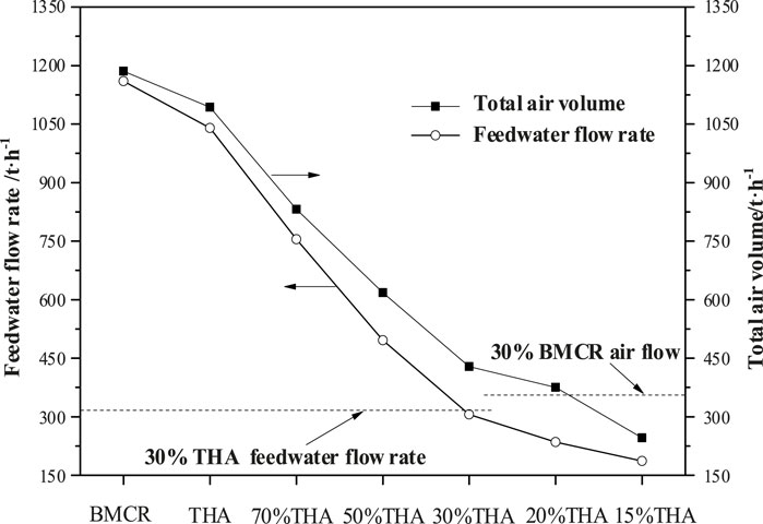
Figure 8. Unit load corresponding to minimum airflow and minimum flow rate.
Assuming the boiler is operating at 25% THA condition and is then unloaded to 15% THA condition, with the main steam pressure remaining constant, and the feedwater flow controlled according to the water-coal ratio, the mass flow velocity in the water-cooled wall region and the subcooling at the outlet of the economizer gradually decrease, as shown in Figure 9. By adhering to constraints such as the mass flow velocity in the spiral tube not falling below 500 kg·m-2·s-1 and the outlet subcooling of the economizer being within 10°C–15°C, while also considering a certain safety margin, the minimum flow rate can be set at 20% of the THA feedwater flow. Calculating the dry-wet transition point of the unit based on this minimum flow rate reveals that, as the load decreases, the outlet superheat of the separator gradually decreases. Around 20% THA, the outlet superheat of the separator reduces to 0°C, indicating the boiler transitions to wet operation.
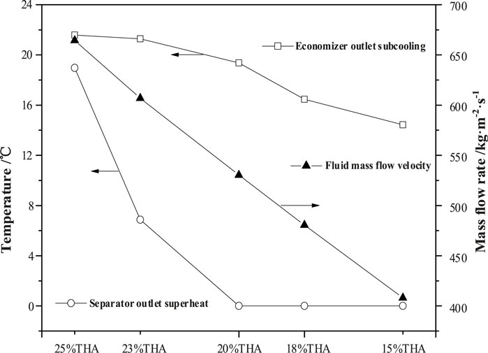
Figure 9. Dry-wet transition point of the boiler.
Based on the above analysis, the boiler operates in dry mode within the load range of 30%–20%, with the feedwater flow controlled according to the water-coal ratio and the total airflow controlled according to the air-coal ratio. When the boiler load falls below 20%, it transitions to wet-recirculation operation mode, maintaining the total airflow at 30% of BMCR minimum airflow, and the mass flow within the water-cooled wall tubes at 20% THA minimum flow. In this configuration, the fluid flow path involves water entering from the inlet manifold of the economizer, passing through the economizer, furnace, and then to the steam-water separator. After separation, the separated water is sent back to the economizer through a water storage tank at the bottom of the separator by the furnace water circulation pump. The separated steam enters the superheater system and is finally drawn out through the main steam pipeline.
During wet operation, the coal feed rate affects the dryness fraction of the working fluid at the outlet of the water-cooled wall, thereby influencing the circulation water flow rate and working fluid parameters. Taking the 15% THA condition as an example, based on the load-coal quantity curve corresponding to a coal feed rate of 25 t/h, the main reheated steam temperature is calculated to be 438/403°C, however, the generated power at the turbine side does not meet the requirement of 15% load. Increasing the coal feed rate to 27.36 t/h raises the main reheated steam temperature to 524/504°C, thereby achieving the 15% load requirement, as depicted in Figure 10. Further increasing the coal feed rate continues to elevate the main reheated steam temperature. By controlling the main steam flow rate through valves to maintain the unit’s power generation, the thermal consumption of the turbine decreases slightly, however, the outlet subcooling of the economizer drops to a low level, posing a risk of gasification within the tubes. Therefore, the most economical coal feed rate for the unit at 15% load is 27.36 t/h. Continuing to increase coal feed rates and raise steam temperatures may lead to boiler overheating.
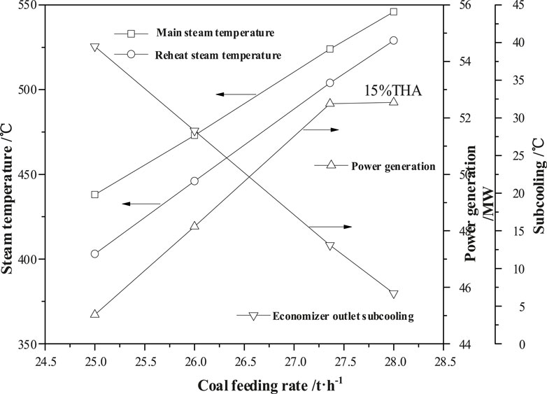
Figure 10. Thermodynamic parameters of 15% THA wet operation condition.
During the boiler startup process in wet operating conditions, significant losses in both working fluid and heat occur as the boiler feedwater expands through the drain valve into the condenser (Ma et al., 2022). Table 2 presents a comparison of the economic efficiency between the minimum flow rate operation and the boiler feedwater circulation operation at 15% of THA during wet operation. It can be observed that although boiler feedwater circulation entails drawbacks such as high initial investment and frequent start-stop cycles, it can notably reduce the coal consumption rate for power generation during wet operation.

Table 2. Comparison of wet operation schemes.
A comparison of coal feeding rate, De-NOx inlet flue gas temperature, and exhaust gas temperature at various loads is shown in Figure 11. The coal feeding rate varies linearly with load above 30%, while the outlet of the air preheater gradually decreases. During low-load operation below 30%, both coal feeding rate and air flow deviate from the original load curve. For example, at a load of 15%, with a corresponding total airflow of 245.9 t/h according to the air-coal ratio, the calculated oxygen content at the furnace outlet is 3.24%, and the exhaust gas temperature is 85.8°C. In contrast, at 30% BMCR, the corresponding airflow is approximately 355.9 t/h, resulting in a calculated oxygen content of 8.35% and an exhaust gas temperature of 87.9°C. During actual boiler operation, the airflow at low loads is also affected by factors such as the opening degree of the air supply fan blades, furnace air leakage, and tube wall overheating. Actual airflow often exceeds the minimum constrained airflow, and the oxygen content at a load of 15% may sometimes approach 10%. An increase in furnace airflow at low loads leads to an increase in exhaust gas temperature and oxygen content, resulting in decreased boiler efficiency. Therefore, reducing air leakage and adjusting the opening degree of the air supply fan at low load can be employed to decrease the oxygen content at the furnace outlet and improve boiler efficiency.
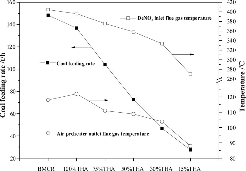
Figure 11. Coal feeding rate, de-NOx inlet flue gas temperature, and exhaust gas temperature at different loads.
The inlet flue gas temperature of the De-NOx system decreases with the reduction of the coal feeding rate and the decrease in boiler thermal efficiency. To ensure the efficient and safe operation of the De-NOx system, many units may transition to wet operation earlier. In this case study, the selected 350 MW unit can ensure that the inlet flue gas temperature for De-NOx is within the reasonable range of 300–400°C at loads above 20% by adjusting the area of the economizer and the opening degree of the flue gas damper. When the unit load is below 20%, and the inlet flue gas temperature for De-NOx is below 300°C, consideration should be given to adopting methods such as flue gas bypass or water bypass to increase the inlet flue gas temperature for De-NOx.
Table 3 presents the calculation results of two schemes, flue gas bypass and water bypass, under the condition of 15% THA. The process of flue gas bypass involves extracting a portion of high-temperature flue gas directly from the outlet of the secondary reheater and delivering it to the De-NOx inlet, bypassing the secondary superheater and secondary economizer. The process of water bypass involves diverting a portion of the feedwater directly to the lower header of the water-cooled wall from the feedwater inlet, bypassing the primary economizer and secondary economizer. From the calculation results, it can be observed that when the inlet flue gas temperature for De-NOx is increased from 270°C to 302°C using bypass methods, both coal consumption and exhaust gas temperature increase. The impact of flue gas bypass on boiler efficiency is smaller than that of water bypass.
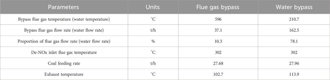
Table 3. Comparisons between the flue gas bypass and water bypass schemes.
Economic indicators such as coal consumption rate and thermal efficiency of the steam turbine. At low loads are of great concern within the industry, but there is still a lack of unified quantitative understanding (Yin et al., 2021). First, the actual coal consumption rate of the unit under operational conditions is calculated using a simulation model, as shown in Figure 12. The actual coal consumption rate during unit operation is significantly influenced by operational parameters and the health status of the unit’s equipment, such as turbine cylinder efficiency and temperature difference across the heater. However, in most simulations, ideal values are assumed. Therefore, the actual coal consumption rate during operation generally tends to be higher than the simulated results, but the trend to load variation remains consistent. As the unit load decreases, the coal consumption rate for electricity generation increases significantly. At a load of 34%, the coal consumption rate for electricity generation increases by approximately 22% compared to that at a load of 87%.
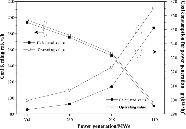
Figure 12. Comparison of simulated and operational values of coal feed rate and coal consumption rate for electricity generation at various loads.
Under the design coal type conditions, the calculation of coal consumption rate, turbine heat consumption rate, and power generation efficiency at various loads is shown in Figure 13. When using the designated coal type for combustion, the exhaust gas temperature decreases, resulting in a significant reduction in the unit’s coal consumption rate compared to the actual operational values. As the unit load decreases, both the coal consumption rate and the turbine heat consumption rate significantly increase, resulting in a decrease in power generation efficiency. At 30% load, the coal consumption rate increases by 13.3% compared to rated power, and at 15% load during wet operation, the coal consumption rate increases by 32.5%. Therefore, during boiler operation at low loads, efforts should be made to reduce the opening degree of the air supply fan and furnace air leakage to decrease the oxygen content at the furnace outlet. Additionally, the minimum feedwater flow rate setting should be reduced to minimize the load transition between dry and wet operation states as much as possible.
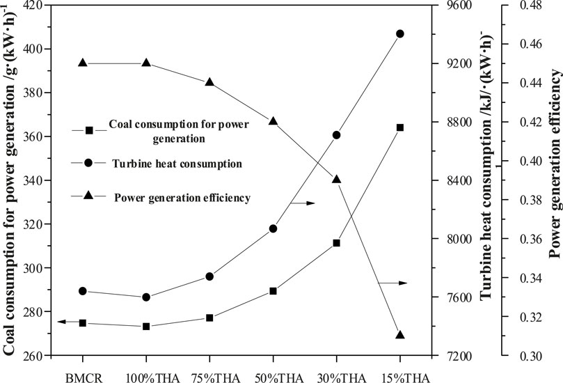
Figure 13. The coal consumption rate for electricity generation, the thermal efficiency of the steam turbine, and the coal consumption rate for electricity generation vary with load under the designated coal type conditions.
(1) When coal-fired power plants operate under variable loads, the establishment of a coupled boiler and turbine model, along with adjustments to the heat transfer coefficients of various heat exchanger modules at different loads, results in flue gas and working fluid temperature distributions that are essentially consistent with design parameters, with errors of less than 5.3%. Comparison with operational parameters of the unit shows a high degree of consistency between simulated and actual values, verifying the accuracy of the calculation model. When the unit deviates from the design coal quality, the coal consumption rate for electricity generation significantly increases.
(2) During low-load operation, boilers are constrained by minimum airflow and minimum feedwater flow rates. To improve the economic efficiency at low loads, while ensuring the hydrodynamic safety of the boiler, efforts should be made to minimize the minimum feedwater flow rate setting and reduce the load transition between dry and wet operation states. During wet operation, boiler water recirculation should be adopted. When the unit load is below 20%, the De-NOx inlet flue gas temperature may be below 300°C. It is recommended to increase the De-NOx inlet flue gas temperature by utilizing the high-temperature flue gas bypass method.
(3) The coupled model established in this study enables the determination of parameters such as coal feeding rate, main steam temperature, and De-NOx inlet flue gas temperature during low-load and wet operation of the unit. This will provide a design basis for the flexibility enhancement of the unit.
The original contributions presented in the study are included in the article/supplementary material, further inquiries can be directed to the corresponding author.
SX: Investigation, Visualization, Writing–original draft. BY: Conceptualization, Writing–review and editing. QZ: Validation, Writing–original draft. XZ: Project administration, Software, Writing–review and editing. FW: Data curation, Writing–original draft. HZ: Supervision, Writing–review and editing.
The author(s) declare that financial support was received for the research, authorship, and/or publication of this article. This project was supported by the Key R&D Program of Shaanxi Province (2024GX-YBXM-458).
Author SX was employed by Huaneng Yingkou Thermal Power Co., Ltd.
Author XZ was employed by Xi’an Thermal Power Research Institute Co., Ltd.
The remaining authors declare that the research was conducted in the absence of any commercial or financial relationships that could be construed as a potential conflict of interest.
All claims expressed in this article are solely those of the authors and do not necessarily represent those of their affiliated organizations, or those of the publisher, the editors and the reviewers. Any product that may be evaluated in this article, or claim that may be made by its manufacturer, is not guaranteed or endorsed by the publisher.
Alobaid, F., Mertens, N., Starkloff, R., Lanz, T., and Epple, B. (2017). Progress in dynamic simulation of thermal power plants. Prog. Energy Combust. Sci. 59, 79–162. doi:10.1016/j.pecs.2016.11.001
Ata, A. B., Alobaid, F., Heinze, C., Almoslh, A., and Epple, B. (2020). Comparison and validation of three process simulation programs during warm start-up procedure of a combined cycle power plant. Energy Convers. Manag. 207, 112547. doi:10.1016/j.enconman.2020.112547
Chang, J., Wang, X., Zhou, Z. J., Chen, H. G., and Niu, Y. G. (2021). CFD modeling of hydrodynamics, combustion and NOx emission in a tangentially fired pulverized-coal boiler at low load operating conditions. Adv. Powder Technol. 32, 290–303. doi:10.1016/j.apt.2020.12.008
Deng, K., Yang, C., Chen, H., Zhou, N., and Huang, S. (2017). Start-Up and dynamic processes simulation of supercritical once-through boiler. Appl. Therm. Eng. 115, 937–946. doi:10.1016/j.applthermaleng.2017.01.016
Jens, H. P., Moritz, H., Dorian, H., Jürgen, N., and Egon, H. (2017). Local steam temperature imbalances of coal-fired boilers at very low load. Energy Procedia 120, 439–446. doi:10.1016/j.egypro.2017.07.206
Klaus, T. (2006). Low load model of a once-through boiler with recirculation. IFAC Proc. Vol. 39, 303–308. doi:10.3182/20060625-4-ca-2906.00057
Li, Z. X., Qiao, X. Q., and Miao, Z. Q. (2021). Low load performance of tangentially-fired boiler with annularly combined multiple airflows. Energy 224, 120131. doi:10.1016/j.energy.2021.120131
Ma, D. F., Zhang, S. Y., He, X., Zhang, J., and Ding, X. (2023). Combustion stability and NOX emission characteristics of a 300 MWe tangentially fired boiler under ultra-low loads with deep-air staging. Energy 269, 126795. doi:10.1016/j.energy.2023.126795
Ma, D. S., Wang, Y., Lv, K., Shi, X. P., Xu, P. J., Zhang, J. Y., et al. (2022). Research progress on flexible transformation technology for coupled energy storage of thermal power units under the "dual carbon" target. Proc. CSEE 42, 136–148.
Pan, E. S., Tian, X. Q., Xu, T., and Wang, X. L. (2020). Critical problems and prospects of flexibility retrofit of thermal power in China. Electr. Power Constr. 41, 58–68.
Ralf, S., Falah, A., Karl, K., Bernd, E., Martin, S., and Felix, B. (2015). Development and validation of a dynamic simulation model for a large coal-fired power plant. Appl. Therm. Eng. 91, 496–506. doi:10.1016/j.applthermaleng.2015.08.015
Shi, H., Wang, W. G., Qu, J., Fang, Q. W., Zhu, P. B., Zeng, L. F., et al. (2010). Technical and economic analysis of boiler high energy water recovery for supercritical 350 MW unit. Therm. Power Gener. 50, 27–31.
Sun, X. D., Jiang, D. J., Ren, Y., and Shao, Y. (2022). Improvement of control method for water supply system during deep peak shaving of supercritical thermal power unit. Northeast Electr. Power Technol. 43, 21–23.
Wang, G. T., Du, M., Zhang, T., and Wu, Z. (2022). Research on coordinated system model and control strategy of thermal power unit under wet operation. J. Eng. Therm. Energy Power 37, 25–32.
Wang, W., Shen, P. Y., Li, X. H., Zhang, G. M., Zeng, D. L., and Liu, J. Z. (2023). Electricity-heat coordinated control strategy for improving the flexibility of a once-through CHP unit. Proc. CSEE 43, 2100–2109.
Wang, X. H. (2022). Influence of deep peak regulation on combustion and denitrification of 600 MW supercritical boiler. Energy Energy Conservation 207, 160–163.
Xu, S. M., Wang, Z. Y., Li, D. C., and Li, P. (2023). Summary of key points in the construction and operation of electric boiler auxiliary peak regulating project. Turbine Technol. 65, 286–288+285.
Yang, L. D., Dong, Z. K., Zhuo, N., Bao, Y. L., Pang, Y., Lu, H. L., et al. (1998). JB/T 8659-1997 Hydrodynamic calculation method for hot water boiler. Boil. Hydrodyn. Calc.
Yin, J., Liu, M., Zhao, Y., Wang, C., and Yan, J. (2021). Dynamic performance and control strategy modification for coal-fired power unit under coal quality variation. Energy 223, 120077. doi:10.1016/j.energy.2021.120077
Yong, Q., Tian, Y., Qian, X., and Li, X. (2022). Retrofitting coal-fired power plants for grid energy storage by coupling with thermal energy storage. Appl. Therm. Eng. 215, 119048. doi:10.1016/j.applthermaleng.2022.119048
Zhang, G. C., Zhou, K., Lu, F., Liu, H. G., Zhou, Z. P., and Zhou, L. Y. (2017). Improvement of control method for water supply system during deep peak shaving of supercritical thermal power unit. Therm. Power Gener. 46, 17–23.
Zhang, P. (2018). Discussion on dry and wet state technology and optimization of operation scheme for deep peak regulating. Heilongjiang Electr. Power 48, 546–550.
Zhao, Y., Liu, M., Wang, C., Wang, Z., Chong, D., and Yan, J. (2019). Exergy analysis of the regulating measures of operational flexibility in supercritical coal-fired power plants during transient processes. Appl. Energy 253, 113487. doi:10.1016/j.apenergy.2019.113487
Keywords: boiler, low load, wet operation, simulation, boiler water circulation, flexibility
Citation: Xu S, Yu B, Zhou Q, Zhang X, Wang F and Zhou H (2024) Simulation of low-load operation for a 350 MW supercritical unit. Front. Energy Res. 12:1448416. doi: 10.3389/fenrg.2024.1448416
Received: 13 June 2024; Accepted: 19 August 2024;
Published: 05 September 2024.
Edited by:
A. S. M. Monjurul Hasan, University of Technology Sydney, AustraliaReviewed by:
Marcin Wołowicz, Warsaw University of Technology, PolandCopyright © 2024 Xu, Yu, Zhou, Zhang, Wang and Zhou. This is an open-access article distributed under the terms of the Creative Commons Attribution License (CC BY). The use, distribution or reproduction in other forums is permitted, provided the original author(s) and the copyright owner(s) are credited and that the original publication in this journal is cited, in accordance with accepted academic practice. No use, distribution or reproduction is permitted which does not comply with these terms.
*Correspondence: Bo Yu, eXVib0BjdW10LmVkdS5jbg==
Disclaimer: All claims expressed in this article are solely those of the authors and do not necessarily represent those of their affiliated organizations, or those of the publisher, the editors and the reviewers. Any product that may be evaluated in this article or claim that may be made by its manufacturer is not guaranteed or endorsed by the publisher.
Research integrity at Frontiers
Learn more about the work of our research integrity team to safeguard the quality of each article we publish.