 Shuilian Xue1
 Zhilong Yin
 Feng Yu
- 1Nanjing Moral Testing and Certification Co., Ltd., Nanjing, China
- 2Xi’an Dynamic Inspection and Testing Co., Ltd., Xi’an, China
- 3School of Electrical Engineering and Automation, Nantong University, Nantong, China
With the large-scale interconnection of wind power generation, the voltage problem of the power system becomes more and more prominent. Compared with adding external reactive power compensation devices, it is more economical and responsive for fans to adjust their control strategies to provide reactive power support. To make full use of reactive power supported by wind turbines, a mathematical model of doubly fed induction generator (DFIG) wind turbines is constructed to characterize the reactive power boundary of wind turbines. Then, active disturbance rejection control (ADRC) is used to generate a voltage control signal to effectively improve the unit’s reactive response speed; in addition, a variable gain coefficient is used to adjust the reactive power output of the unit, which effectively improves the reactive power response speed and its control adaptability and robustness under changing power grid conditions. Finally, a wind turbine generator (WTG) simulation model is built using MATLAB/Simulink simulation software, different fault locations are perturbed, and the effectiveness of reactive power support of the proposed ADRC-based strategy is simulated and verified. The proposed ADRC-based strategy could inject more reactive power to the grid to improve the voltage.
1 Introduction
An important form of clean energy, the installed capacity of wind power has increased rapidly worldwide in recent years, and it has become a considerable industry. With the increasing proportion of new energy sources installed in China and the weak overcurrent characteristics of new energy power electronic equipment, a situation of large-scale new energy stations connecting to weak electricity networks has gradually appeared in some areas of China. It is foreseeable that with the comprehensive construction of large-scale renewable energy, there will be more and more situations of new energy connecting to the weak power grid in the future, and it will gradually become the development trend of new energy grid-connected power generation in the northwest and north China. However, in the scenario of weak voltage support on the system side, the system voltage will drop sharply during the fault period, which may lead to large-scale off-grid renewable energy sources and secondary chain accidents. Therefore, during a period of weak current network failure, the new energy station should not only ensure its own safe ride-through but also make full use of controllable resources to provide safe, fast, and flexible transient voltage support for the system. Generally, with the increasing proportion of renewable energy in power systems, the demand for transient control of new energy stations in weak power network environments will become increasingly prominent, and research into the application of more flexible and efficient multi-objective control methods will be an important development direction (Wang et al., 2020; Zhu et al., 2024; Yang et al., 2024).
Because wind turbines often operate at unit power factor, the reactive power regulation potential of wind turbines has not been utilized (LÓpez et al., 2008; Pannell et al., 2010; Lima et al., 2010). However, due to the low power density of wind energy, wind turbines operate under light load most of the time, and wind turbines have great reactive power potential. The doubly fed induction generator (DFIG) has been widely utilized in wind power systems due to its high efficiency and reliability (Chang et al., 2023). However, the long-distance connection between wind turbine generators (WTGs) and the main power grid results in relatively weak grid strength in the areas where WTGs are located, making them more susceptible to grid fluctuations (Gui et al., 2019; Tsili and Papathanassiou, 2009; Wu et al., 2023). Therefore, wind power grid integration standards require wind turbines to have fault ride-through capability to ensure they remain connected when grid voltage drops and to provide reactive power support to assist in rapid grid voltage recovery (Hu et al., 2014; Zou et al., 2018).
Several studies have proposed solutions to address this issue. One study proposes a voltage control strategy for coordinated static reactive power generators in DFIG that effectively suppresses grid voltage fluctuations. However, this solution may entail additional costs. Another study suggests a model predictive control-based strategy for reactive power voltage control in WTGs to enhance their rapid reactive power regulation capability. However, this method requires high-quality data and may suffer from overfitting issues. Another study proposes a DFIG wind turbine field reactive power output control based on low-voltage ride-through capability assessment, providing a reactive power evaluation index (Xu et al., 2015). However, this strategy may lack precision in reactive power control, and wind turbines need to provide grid reactive power support.
Traditional proportional-integral (PI) controllers struggle to achieve ideal control effects when facing external disturbances. In contrast, active disturbance rejection control (ADRC), developed further from traditional PI control theory, is a control strategy that does not rely on precise system models (Qiming et al., 2024). It offers fast tracking response, low overshoot, and strong disturbance rejection capabilities and has been widely applied in inverter control. For instance, some studies have combined ADRC with fuzzy PI control to improve droop control, achieving stable voltage and frequency through control of the voltage outer loop (Xia et al., 2022; Zhu et al., 2024). Another study introduced linear ADRC into current inner loop control, resulting in better suppression of sub-synchronous oscillations under various conditions. Additionally, applying ADRC in the current inner loop can weaken the coupling between dq currents, while applying it in the outer loop can enhance system disturbance rejection capabilities. Because the focus of wind power system control lies primarily on inverter control within wind turbines, ADRC methods show significant applicability in voltage control. Chang et al. (2023) divided the fault ride-through (FRT) configuration into three parts. A reactive current distribution strategy of DFIG is proposed, considering grid code requirements and stress (Wu et al., 2023). Zhu et al. (2015) addressed the virtual damping flux-based LVRT strategy for DFIG to improve the FRT performance.
To improve the transient response characteristics of wind farms under grid faults, this article introduces ADRC into the wind farm controller and proposes a hierarchical reactive power support strategy based on ADRC for DFIG. First, a mathematical model of DFIG wind turbines is constructed to characterize the reactive power boundary of wind turbines. Second, ADRC is used to generate voltage control signals to effectively improve the unit’s reactive response speed; in addition, a variable gain coefficient is used to accurately adjust the reactive power output of the unit. Finally, simulations are conducted under different short-circuit position conditions to verify the effectiveness of the proposed strategy.
2 Modeling of a wind turbine generator
The expression of a wind turbine blade model that captures the mechanical power from the wind is as in Equation 1
where cp, λ, and β are the power coefficient, tip-speed ratio, and pitch angle, respectively; ρ is the air density; A represents the swept area by the wind blade; and vw is the wind speed (Rafiee et al., 2022; Dejian et al., 2024).
cp is a non-linear function given by Equations 2–4:
where
where ωr is the rotor speed of WTG.
The power reference for maximum power point tracking (MPPT) operation, PMPPT, is expressed as in Equation 5:
where kg is a constant coefficient, λopt represents the optimal value of λ, and cp,max is the maximum value of cP.
3 Characterization of the reactive power boundary of a DFIG and ADRC-based reactive power strategy
3.1 Characterization of DFIG reactive power boundary
The reactive power of DFIG is mainly determined by its reactive power control scheme. If this scheme is improperly set, and the reactive power control setting exceeds the reactive power limit of the wind turbine generator, excessive heating of the stator will lead to the shutdown of the wind turbine generator (Xiao et al., 2019; Kayikci and Milanovic, 2007). Therefore, it is crucial to understand and characterize the reactive power boundary of the unit so that its reactive support potential can be effectively utilized during grid faults.
The primary boundary of DFIG reactive power depends on rotor current, stator current, and rotor voltage. Given the active power of the DFIG, these three physical quantities can be used as constraints to determine the maximum reactive power that the unit can absorb or generate. This boundary is depicted using a P-Q curve diagram.
The power flow on the stator winding and rotor winding is typically described in the P-Q curve diagram. Assuming the wind turbine operates in maximum power point tracking (MPPT) mode and neglecting the impedance of the step-up transformer, the stator voltage is considered as 1 per unit (pu) or normalized value.
By thoroughly understanding and characterizing the reactive power boundary of the DFIG, wind turbine operation in the grid can be effectively managed, ensuring its stability and reliability. Additionally, appropriate reactive power support can be provided when necessary to maintain stable grid operation.
(1) When considering the constraint of rotor current, the power on the stator side is expressed by rotor current, as shown in Equation 6:
where US is the stator side voltage, Ir is the rotor side current, and * is the conjugate. Zs is the stator side impedance, and Zm is the magnetization impedance.
To highlight the influence of rotor current on power, Ir is extracted, and Equation 6 is rewritten as Equation 7:
Assuming that the amplitude of the rotor current is constant and the angle changes, Equation 7 can be expressed as a circle on the complex plane. The center c of the circle is shown in Equation 8, and the radius r is shown in Equation 9.
The DFIG active power and reactive power can be expressed as:
where s is slip, and Pr and Ps are the output power of the rotor and stator, respectively.
Substituting Equations 10, 11, the total power can be obtained as in Equation 12:
where γ is the angle of the rotor current.
Considering the constraint of the rotor current, the amplitude of the rotor current is constant, and the angle changes. The image of the total power is an ellipse on the complex plane. Due to the first term on the right of the equal sign, the reactive power boundary moves down, as shown in the green curve of Figure 1.
(2) Considering the stator current constraint, the power of the stator side and the rotor side are expressed by the stator current, respectively, as in Equations 13, 14:
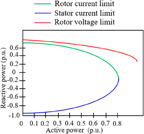
Figure 1. Reactive power limitation with different active power boundaries.
Under the representation of the stator current, the center of the reactive power image is close to the origin, so the stator current is the limiting factor of the boundary on the constructed P-Q diagram, as in the blue curve of Figure 1.
(3) When considering the constraint of rotor voltage, the power on the stator and rotor sides is expressed by rotor voltage, respectively, as shown in Equations 15, 16:
The centers of Equations 15, 16 have great negative deviation on the imaginary axis of the complex plane, and the radius is inversely proportional to the absolute value of the slip. Therefore, the rotor voltage only limits the upper boundary of the P-Q diagram when the absolute value of the slip is very high, as shown by the red dotted line in Figure 1.
Figure 1 shows the reactive power boundary of the 3 MW doubly fed wind turbine used in this article, that is, the P-Q curve. The rotor current is the dominant factor limiting the maximum generated reactive power, and the stator current is the dominant factor limiting the maximum absorbed reactive power. Compared with the curve, the reactive power boundary under different active working points can be obtained.
This article proposes a reactive power support strategy for WTGs. ADRC is used to generate a voltage control signal to effectively improve the unit’s reactive response speed; in addition, a variable gain coefficient is used to accurately adjust the reactive power output of the unit. Thus, it could achieve reactive power support for the wind farm.
3.2 Reactive power support strategy of a station based on an active disturbance rejection controller
A traditional station controller uses PI controllers to deal with the change in voltage, so it is difficult to find a balance between response speed and stability. In this article, a station controller based on ADRC is proposed.
The response speed and robustness of the control system are improved by actively estimating and compensating for the internal and external disturbances of the system. There are vector DFIG voltage equations and flux linkage equations in the dq coordinate system rotating at synchronous speed, as in Equations 17, 18:
where Ls, Lm, and Lr are the inductance of the stator, magnetizing, and rotor, respectively. ψs and ψr are the flux linkage of the stator and rotor, respectively. Rr and Rs are the resistance of the stator and rotor, respectively.
The DFIG equivalent circuit in vector form can be derived using the above equation, as shown in Figure 2.

Figure 2. DFIG equivalent circuit.
When connecting the grid, because the DFIG stator is directly connected to the grid, the stator voltage Us is equal to the grid voltage (Ug). Therefore, voltage could be expressed as in Equation 19:
In the DFIG system, power transmission is mainly carried out through the stator side, so the fluctuation of the stator current directly reflects the change in the power output. Because the power transfer is proportional to the product of voltage and current and depends on the phase angle between them, the dynamic characteristics of voltage and current on the stator side are very important for the power control and stability of the system. In this article, the fluctuation of grid voltage is evaluated by the change of the stator current, as in Equation 20:
Selecting Ug as the state variable yields x1 = Ug, x2 = fw = Ug/k-LmdIr/dkt-jω1Ψs/k, u = Is. As a result, Equation 18 can be rewritten as:
where fw is the external disturbance, including current disturbance, power disturbance, and error disturbance of model parameters of the system.
To design a linear extended state observer (LESO)-based voltage control strategy conveniently, the system state vector x = [x1, x2]T is defined, and Equation 21 could be expressed in matrix form, as shown in Figure 3.
where A, B, E and h could be expressed as in Equation 23
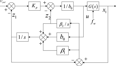
Figure 3. ADRC-based reactive power control diagram.
Defining z = [z1, z2]T as the state vector of LESO, where z1 is the observed value of x1, and z2 is the observed value of x2, the corresponding first-order LESO equation for Equation 22 can be designed as in Equation 24:
where C = (Wu et al., 2023); u is the input control variable; y^ is the input of LESO; y is the observed value of LESO; and L = [β1, β2]T is the error feedback gain matrix of LESO, which is designed according to the bandwidth of LESO.
3.3 Definition of a control coefficient for the reactive power controller
The reactive power control is used to respond to the transient voltage change, and the specific formula is as in Equation 25:
where Q ref is the reactive power command of WTG, and Δu is the deviation between the grid voltage and the reference voltage, respectively. k Q of the wind turbine is the gain coefficient of WTG, which determines the reactive power output by the wind turbine during the fault. Under the constant gain coefficient, it is difficult to make full use of the reactive power support capacity of WTG.
Considering the different reactive power output capabilities of various operating conditions, a variable gain coefficient, as shown in Equation 26, is proposed to realize the adaptive control of the unit:
where Qmax and Qmin represent the maximum reactive power that WTG can emit and absorb under a certain active output, and umax and umin represent the voltage of the grid connection point when the wind turbine generator absorbs the maximum reactive power and emits the maximum reactive power. α is the regulating factor. In this article, umax is set to 1.10, and umin is set to 0.9.
4 Characterization model system and case studies
To verify the feasibility of the control strategy proposed in this article, a simulation example system with a wind farm is built based on MATLAB/Simulink software, as shown in Figure 4. The wind farm consists of 20 sets of 3 MW-DFIGs. The wind farm is connected to the power grid through 110 kV transmission lines of 10 km. The parameters of the ADRC and PI controller are shown in Table 1, and the parameters of the model system are shown in Table 2.
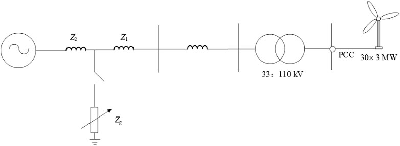
Figure 4. Model system.
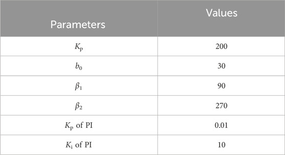
Table 1. Control parameters of the ADRC and the PI controller.
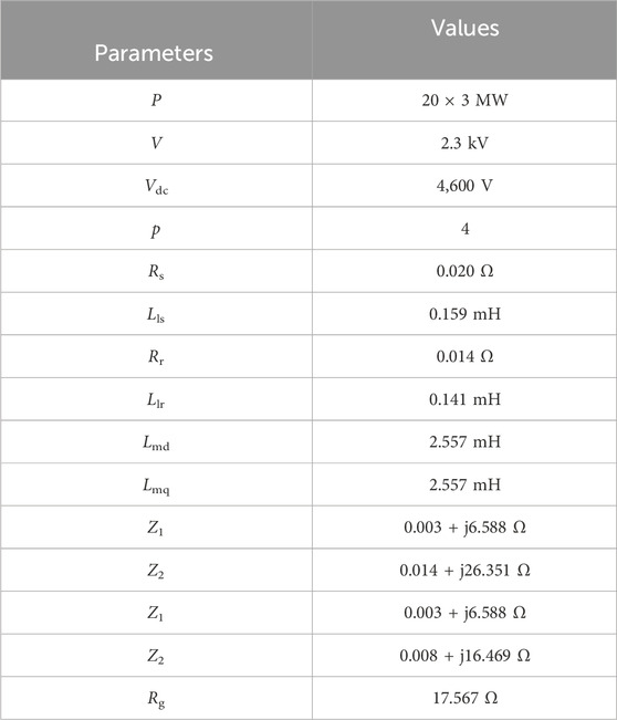
Table 2. Parameters of model system.
When the fault location, fault duration, and fault degree are different, the voltage drop degree of the grid point of the wind farm is different, and the reactive power demand for supporting the grid point voltage system is different. The reactive power support capacity of wind turbines is different under different operating conditions. The effectiveness of the proposed strategy is verified under various sizes of fault, durations of fault, and operating conditions by comparing the following two schemes: Scheme #1: ADRC-based reactive power support strategy and Scheme 2: PI-based reactive power support strategy.
4.1 Impact of fault duration
In Case 1 (Fault duration = 0.3 s, Wind speed = 10 m/s), with the rapid intervention of the ADRC controller, each wind turbine can inject reactive power more quickly. At 6.2 s, the grid-connected voltages of the ADRC control strategy and PI control strategy reach 0.613 p.u. and 0.593 p.u., respectively, as shown in Figure 5, because the ADRC controller has better response characteristics than the PI controller. Before the fault is cleared (6.3 s), the reactive power output of the wind farm with ADRC control strategy and PI control strategy is 0.270 p.u. and 0.077 p.u., respectively, as shown in Figure 5.
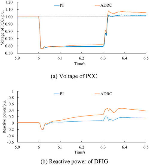
Figure 5. Results for Case 1. (A) Voltage of point of common coupling (PCC), and (B) reactive power of DFIG.
In Case 2 (Fault duration = 0.5 s, Wind speed = 10 m/s), the fault duration was increased from 0.3 s to 0.5 s, and the reactive power support of the ADRC controller and PI controller was close to the maximum after 0.3 s, so the two control strategies showed similar voltage levels during 6.3 s–6.5 s, as shown Figure 6. The ADRC-based Q control strategy shows better support performance under various fault durations than the PI-based Q control strategy.
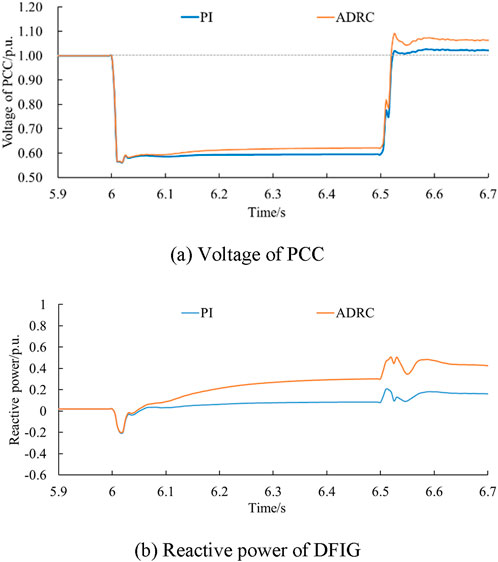
Figure 6. Results for Case 2. (A) Voltage of PCC, and (B) reactive power of DFIG.
4.2 Impact of sizes of fault
In Case 3 (Fault duration = 0.3 s, Wind speed = 10 m/s, Severe Fault), the grounding resistance is reduced from 17 Ω to 10 Ω, the voltage level of the grid connection point of the wind farm is further reduced under the condition of increasing disturbance, and the minimum voltage is reduced from 0.563 p.u. to 0.357 p.u., as shown Figure 7. The ADRC-based Q control strategy shows better support performance under various sizes of faults than those of the PI-based Q control strategy.

Figure 7. Results for Case 3. (A) Voltage of PCC, and (B) reactive power of DFIG.
4.3 Impact of operating conditions
In Case 4 (Fault duration = 0.3 s, Wind speed = 9 m/s) and Case 5 (Fault duration = 0.3 s, Wind speed = 8 m/s), the received wind speed of the wind farm decreased from 10 ms to 1–9 m s−1 and 8 m s−1. With the decrease of wind speed, the highest voltage levels during the fault period gradually decreased, which were 0.617 p.u., 0.610 p.u., and 0.603 p.u. in turn, as shown in Figures 8, 9. At various wind speeds, the ADRC-based Q control strategy shows better response characteristics than the PI control strategy.

Figure 8. Results for Case 4. (A) Voltage of PCC, and (B) reactive power of DFIG.
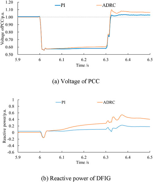
Figure 9. Results for Case 5. (A) Voltage of PCC, and (B) reactive power of DFIG.
5 Conclusion
To improve the transient response characteristics of DFIGs under grid fault, this article characterizes the DFIG reactive power boundary and proposes a reactive power control strategy for wind turbines based on ADRC. Through simulation and analysis, the following conclusions are drawn:
1) The reactive power boundaries are investigated, which can tap the reactive power support potential of units at different wind speeds.
2) Considering the characteristics of ADRC, the use of an ADRC-based Q control strategy instead of a PI controller has a faster response and injects more reactive power to compensate for the voltage dip during fault under various fault sizes, fault durations, and operating conditions.
Future research could address fault clearing, the transient overvoltage problem, the lack of a cooperative control strategy with reactive power support components, improving reactive power support capacity, and restraining transient overvoltage.
Data availability statement
The raw data supporting the conclusions of this article will be made available by the authors, without undue reservation.
Author contributions
SX: writing–original draft, writing–review and editing, methodology. ZY: methodology, writing–original draft, writing–review and editing, conceptualization, data curation, formal analysis, investigation, resources. ZW: data curation, formal analysis, resources, visualization, writing–original draft. FY: data curation, resources, supervision, validation, writing–original draft, writing–review and editing. HC: writing–original draft.
Funding
The author(s) declare that no financial support was received for the research, authorship, and/or publication of this article.
Conflict of interest
Authors SX and HC were employed by the Nanjing Moral Testing and Certification Co., Ltd. Authors ZY and ZW were employed by the Xi’an Dynamic Inspection and Testing Co., Ltd.
The remaining author declares that the research was conducted in the absence of any commercial or financial relationships that could be construed as a potential conflict of interest.
Publisher’s note
All claims expressed in this article are solely those of the authors and do not necessarily represent those of their affiliated organizations, or those of the publisher, the editors and the reviewers. Any product that may be evaluated in this article, or claim that may be made by its manufacturer, is not guaranteed or endorsed by the publisher.
References
Chang, Y., Kocar, I., Farantatos, E., Haddadi, A., and Patel, M. (2023). Short-circuit modeling of DFIG-based WTG in sequence domain considering various fault-ride-through requirements and solutions. IEEE Trans. Power Deliv. 38 (3), 2088–2100. doi:10.1109/tpwrd.2023.3235985
Dejian, Y., Li, J., Jin, Z., Gangui, Y., Xin, W., Lei, D., et al. (2024). Sequential frequency regulation strategy for DFIG and battery energy storage system considering artificial deadbands. Int. J. Electr. Power and Energy Syst. 155, 1–14. doi:10.1016/j.ijepes.2023.10950
Gui, Y., Wang, X., Blaabjerg, F., and Pan, D. (2019). Control of grid-connected voltage-source converters: the relationship between direct-power control and vector-current control. IEEE Ind. Electron. Mag. 13 (2), 31–40. doi:10.1109/mie.2019.2898012
Hu, S., Zou, X., and Kang, Y. (2014). A novel optimal design of DFIG crowbar resistor during grid faults. Int. Power Electron. Conf. Hiroshima, Jpn., 555–559.
Kayikci, M., and Milanovic, J. V. (2007). Reactive power control strategies for DFIG-based plants. IEEE Trans. Energy Convers. 22 (2), 389–396. doi:10.1109/tec.2006.874215
Liang, X., Tianfu, S., Xinyu, L., Xianfeng, T., and Denghua, D. (2022). Research on double closed-loop ADRC control strategy of wind power grid-connected inverter. Shandong Electr. Power Technol. 49 (11), 70–77.
Lima, F. K. A., Luna, A., Rodriguez, P., Watanabe, E. H., and Blaabjerg, F. (2010). Rotor voltage dynamics in the doubly fed induction generator during grid faults. IEEE Trans. Power Electron. 25 (1), 118–130. doi:10.1109/tpel.2009.2025651
López, J., GubÍa, E., Sanchis, P., Roboam, X., and Marroyo, L. (2008). Wind turbines based on doubly fed induction generator under asymmetrical voltage dips. IEEE Trans. Energy Convers. 23 (1), 321–330. doi:10.1109/tec.2007.914317
Pannell, G., Atkinson, D. J., and Zahawi, B. (2010). Minimum-threshold crowbar for a fault-ride-through grid-code-compliant DFIG wind turbine. IEEE Trans. Energy Conver 25 (3), 750–759. doi:10.1109/tec.2010.2046492
Qiming, C., Zhou, W., Cheng, Y., and Lei, Z. (2024). Study on suppression of subsynchronous oscillation of doubly-fed fan based on linear active disturbance rejection control. Electr. Power Constr. 1-14 -01-27.
Rafiee, Z., Heydari, R., Rafiee, M., Aghamohammadi, M. R., and Blaabjerg, F. (2022). Enhancement of the LVRT capability for DFIG-based wind farms based on short-circuit capacity. IEEE Syst. J. 16 (2), 3237–3248. doi:10.1109/jsyst.2022.3153887
Tsili, M., and Papathanassiou, S. (2009). A review of grid code technical requirements for wind farms. IET Renew. Power Gener. 3 (3), 308–332. doi:10.1049/iet-rpg.2008.0070
Wang, X., Taul, M. G., Wu, H., Liao, Y., Blaabjerg, F., and Harnefors, L. (2020). Grid-synchronization stability of converter-based resources an overview. IEEE Open J. Ind. Appl. 1, 115–134. doi:10.1109/ojia.2020.3020392
Wu, H., Xu, H., Li, Z., Zhao, R., and Hu, J. (2023). Reactive current distribution strategy of DFIG’s RSC and GSC considering electromagnetic stress and grid codes requirement. IEEE Trans. Energy Conver 38 (1), 273–283. doi:10.1109/tec.2022.3218708
Xiao, X., Yang, R., Zheng, Z., and Wang, Y. (2019). Cooperative rotor-side SMES and transient control for improving the LVRT capability of grid-connected DFIG-based wind farm. IEEE Trans. Appl. Super. 29 (2), 1–5. doi:10.1109/tasc.2018.2881315
Xu, H., Ma, X., and Sun, D. (2015). Reactive current assignment and control for DFIG based wind turbines during grid voltage sag and swell conditions. J. Power. Electron. 15 (1), 235–245. doi:10.6113/jpe.2015.15.1.235
Yang, D., Wang, X., Chen, W., Jin, Z., Jin, E., Gangui, Y., et al. (2024). Adaptive frequency droop feedback control-based power tracking operation of a DFIG for temporary frequency regulation. IEEE Trans. Power Syst. 39, 2682–2692. doi:10.1109/tpwrs.2023.3277009
Zhu, D., Wang, Z., Hu, J., Zou, X., Kang, Y., and Guerrero, J. M. (2024). Rethinking Fault ride-through control of DFIG-based wind turbines from new perspective of rotor-port impedance characteristics. IEEE Trans. Sustain. Energy 15, 2050–2062. doi:10.1109/TSTE.2024.3395985
Zhu, J. R., Chen, Z., Wu, X., and Deng, F. (2015). Virtual damping flux-based LVRT control for DFIG-based wind turbine. IEEE Trans. Energy Convers. 30 (1), 714–725. doi:10.1109/tec.2014.2385966
Keywords: wind power integration, doubly fed induction generators (DFIGs), reactive power support, ADRC, voltage control
Citation: Xue S, Yin Z, Wang Z, Yu F and Chen H (2024) Reactive power regulation strategy for WTGs based on active disturbance rejection control. Front. Energy Res. 12:1447094. doi: 10.3389/fenrg.2024.1447094
Received: 11 June 2024; Accepted: 14 August 2024;
Published: 04 September 2024.
Edited by:
Yonghui Liu, Hong Kong Polytechnic University, Hong Kong SAR, ChinaReviewed by:
Jun Cong Ge, Jeonbuk National University, Republic of KoreaXiaokang Liu, Polytechnic University of Milan, Italy
Copyright © 2024 Xue, Yin, Wang, Yu and Chen. This is an open-access article distributed under the terms of the Creative Commons Attribution License (CC BY). The use, distribution or reproduction in other forums is permitted, provided the original author(s) and the copyright owner(s) are credited and that the original publication in this journal is cited, in accordance with accepted academic practice. No use, distribution or reproduction is permitted which does not comply with these terms.
*Correspondence: Feng Yu, eXVmZW5nNjI4QG50dS5lZHUuY24=