 Ji Xiaotong1,2
 Jiang Kezheng
 Wang Chenyu
 Liu Dan
- 1State Key Laboratory of Advanced Electromagnetic Engineering and Technology, School of Electrical and Electronic Engineering, Huazhong University of Science and Technology, Wuhan, China
- 2State Grid Hubei Electric Power Research Institute, Wuhan, China
- 3College of Information Science and Engineering, Northeastern University, ShenYang, China
With the continuous advancement of science and technology, there is a growing global focus on new energy sources. Despite the rapid progress of offshore wind power generation systems, they are still plagued by issues such as significant transmission loss, limited transmission distance, and low-frequency oscillation, which hinder further development. To address these challenges, the Flexible Direct Current Transmission System (VSC-HVDC) has emerged as a widely studied solution. The integration of energy storage power stations presents new opportunities for enhancing offshore wind power transmission systems. These power stations not only serve as energy buffer pools to reduce transmission loss but also improve transmission efficiency through intelligent regulation and control, effectively mitigating low-frequency oscillation. This article introduces an optimization control parameter design method based on sensitivity analysis to enhance the stability of MTDC based on MMC. It outlines the topology structure of the offshore VSC-HVDC system, covering the main circuit and control system. Additionally, the article delves into the derivation of the small signal stability model of the system and investigates the selection of control parameters based on the eigenvalue objective function. Lastly, it analyzes the impact of the control system on the stability of the wind power flexible direct output converter station, highlighting the significant influence of control system parameters on the small signal stability of MTDC systems based on MMC. The MMC parameter selection strategy proposed in this paper is shown to effectively enhance system stability.
1 Introduction
Although flexible direct transmission systems based on offshore wind power have been widely studied, parameter selection of modular multilevel controllers and their stabilisation control considering energy storage plants have rarely been investigated. Offshore wind farms (Fu et al., 2022; Rong et al., 2019), as a clean and sustainable energy solution, can meet the demand for renewable energy (Haegel and Kurtz, 2022; Yi et al., 2018) in various countries and have gained rapid development. Flexible direct transmission systems are widely used as they can transmit power to load centres efficiently and stably. The energy storage power station uses various battery technologies (such as lithium-ion battery, sodium sulfur battery, lead-acid battery, etc.) or other energy storage methods (such as hydraulic energy storage, thermal energy storage, compressed air energy storage, etc.) to store and release electric energy (Wang et al., 2021). They can serve as a buffer pool for power, reducing transmission losses and improving transmission efficiency. Additionally, they can effectively suppress low-frequency oscillations through intelligent regulation to ensure the stable operation of offshore wind farms. Therefore, this paper investigates the selection of mmc parameters and its stabilisation control method for the flexible direct feeder converter station of energy storage power plant, which is of great research significance.
Modular Multilevel Converter (MMC)(Karwatzki and Mertens, 2018) is a key technology in flexible DC transmission systems, widely used in the field of power transmission due to its high voltage capability, high power density, high reliability, high efficiency, and other advantages. VSC-HVDC (Song and Breitholtz, 2016) is a new type of direct current transmission technology based on voltage source converters, using fully controlled power devices, and its transmission capacity can reach ultra-high voltage levels. In the context of the construction of China’s new power system, the advantages of flexible DC transmission technology will be further highlighted in response to major needs such as the safety and stability improvement of new energy transmission and multi DC feeding into the power grid. In reference (Wang et al., 2022), In order to improve the control performance of the controller and suppress the system oscillation, a new control method based on damping compensation is proposed. The simulation results show that the proposed method can effectively improve the anti-interference ability of the flexible direct system, accurately compensate the damping and maintain the stability of the DC voltage. In reference (Wen et al., 2020), aiming at the problem of voltage transient stability in the current flexible direct system, and considering the system communication delay, the author proposes an improved PCC DC voltage compensation scheme, which includes multiple controllers to compensate the voltage signal of the input controller. Through the simulation analysis of the multi node system, it is verified that the proposed control strategy can effectively improve the voltage transient stability of the flexible direct system, Effectively alleviate network delay. In reference (Wang et al., 2023), aiming at the problems of power grid turbulence and power quality decline caused by large-scale electronic devices when new energy is connected to the grid, the author proposes an improved droop control method based on voltage compensation, which can accurately control the constant power load in the power grid, and can synchronously optimize the system bus voltage and power to ensure the accurate distribution of active power. Moreover, the DC boost converter in the system is directly connected to the bus, which greatly reduces the cost. In reference (Zheng et al., 2024), with the increasing maturity of MMC technology and its extensive application in offshore wind farms, broadband Oscillation events in power systems are becoming more and more serious. To solve this problem, the author proposes a new control strategy based on impedance analysis method, which considers the practical problems faced by submarine cables in application, establishes a detailed system model, and proposes an optimized active damping control method for broadband oscillation mechanism. Finally, the simulation results show that the proposed method can enhance the control performance of the grid connected controller and effectively reduce the broadband oscillation of the system.
The conventional coordinated control strategies for MMC-MTDC systems primarily comprise master-slave control, voltage sag control, and voltage margin control. In reference (Yang et al., 2023), the author puts forward an integrated distributed control approach based on PI controller. This method involves establishing the small signal model of the system and analyzing the dynamic impact of the proposed integrated distributed controller on the flexible direct transmission system. The proposed approach enables accurate adjustment of the DC system voltage and precise distribution of active power. In reference (Sun et al., 2023), in view of the shortcomings of the single control method, the author considers the combination of power/voltage droop control and current/voltage droop control, and proposes a new control strategy based on the power distribution in the steady state. The rationality and superiority of the proposed method are verified by simulation. Reference (Shahriari et al., 2020) addresses the issue of DC grid fault protection in MMC-MTDC systems and proposes a novel energy-based control strategy. This method maintains a constant DC grid voltage through reactive power compensation, ensuring accurate branch and branch energy balance control during DC faults.Additionally, this strategy can greatly reduce transient overvoltages across the equivalent arm capacitors and suppress zero-sequence current in the control loop. Reference (Wu et al., 2020) proposes an active damping control method based on MMC-MTDC transmission system for calibrating M-DCPFC in response to power oscillations caused by unbalanced AC power grids. Virtual damping is introduced into the calculation of transmission line power, reducing fluctuations in DC current and effectively suppressing DC power oscillations.
The Grid Side Converter (Jiao et al., 2021), as one of the key equipment in flexible DC transmission systems, converts AC electrical energy into DC electrical energy and delivers it to the receiving end through DC cables. Compared with traditional HVDC systems, flexible DC systems adopt more advanced GSC technology, which has higher controllability and flexibility. GSC converts AC energy into controllable DC energy by rectifying and converting it. At the same time, bidirectional power flow can be achieved, which can convert AC electrical energy into DC electrical energy and deliver it to the receiving end, as well as invert the DC electrical energy from the receiving end into AC electrical energy and inject it into the power system. In reference (Wu and Guo, 2024), the author combines the current source converter with the DC voltage rise and fall, and proposes an improved integrated control strategy. The control strategy improves the overall utilization of the switch duty cycle, reduces the service time of the main switch, and improves the system efficiency and the quality of the output voltage. This method can not only ensure the power quality at the grid side, but also ensure the accurate voltage output, and avoid the use of zero vector. In order to address the challenge of voltage regulation for subsequent level DC/DC converters in power side converters, reference (Yu et al., 2023) proposes a synchronization optimization method that can track local output power during system transients and achieve synchronization optimization. In reference (Lee et al., 2024), in view of the DC bus voltage instability and controller design difficulties caused by a large number of power electronic equipment connected to the grid, the author proposes a new bi-directional active power control method, which can ensure the system stability without using pulse modulation switches, effectively reduce the overshoot problem, and maintain the DC bus voltage stability.To sum up, developing a high-power and high gain converter can not only improve the generation efficiency and capacity of offshore wind power system, but also enhance the stability and reliability of the system, which is of great significance to promote the development of offshore wind power.
In this paper, factors such as the characteristics of each component, control strategy and electrical characteristics of the MMC-MTDC system are investigated. The specific research steps in this paper are as follows:
1. A generalised model of the MMC-MTDC system is developed in the study, taking into account the characteristics of each component, the control strategy and the electrical characteristics. This model helps to deeply understand the dynamic characteristics of the system and the interactions between various subsystems, and provides a solid foundation for subsequent analysis and optimisation.
2. For the flexible direct current transmission (HVDC) system, the influence of the control system on its stability is analysed in detail. This analysis helps to reveal the role and potential problems of the control strategy in maintaining the stability of the system, and provides theoretical support for optimising the control system.
3. An optimal control parameter selection method based on sensitivity analysis is proposed. This method determines the control parameters that have the greatest influence on system stability through sensitivity analysis and optimises them on this basis, ensuring the stability and reliability of the control system under different operating conditions.
4. Through the simulation results, the parameters of the control system on the stability of the system has with a greater impact, verifying the rationality and effectiveness of the optimal control parameter design method proposed in this paper.
The practical significance of the research in this paper is significant in that the stability of the MMC-MTDC system is significantly improved by optimising the control system parameters. This is of great significance for improving the reliable operation of power systems and reducing the occurrence of faults in practical engineering. The optimal control parameter selection method proposed in the study provides an effective tool for power engineers to help them better balance the system stability and performance when designing and adjusting the control strategy, and to improve the overall system operation efficiency. The research results provide a scientific basis and reference for the design, operation and maintenance of the flexible DC transmission system, which can help to be applied and promoted in practical engineering and promote the development of the power system in the direction of higher efficiency and stability. Through the establishment of generalised models and optimised control strategies, this research provides new ideas and methods for the development and improvement of flexible DC transmission technology, and promotes the technological progress and innovation in this field.
2 Small signal modeling of MMC grid connected system in offshore wind farm
In order to study the parameter influence of multi terminal VSC-MTDC system, this section takes the four terminal VSC-MTDC transmission system as an example for modeling, including the offshore wind power side sending converter station (wfvsc), energy storage system and the onshore grid side receiving converter station (gsvsc).Furthermore, the small signal model of the system is obtained by linearizing the stable operating point. Figure 1 shows the structure of the four terminal flexible direct system, and Figure 2 shows the structure of the energy storage system at the offshore wind power generation side.
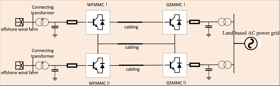
Figure 1. MTDC system of offshore wind farm.
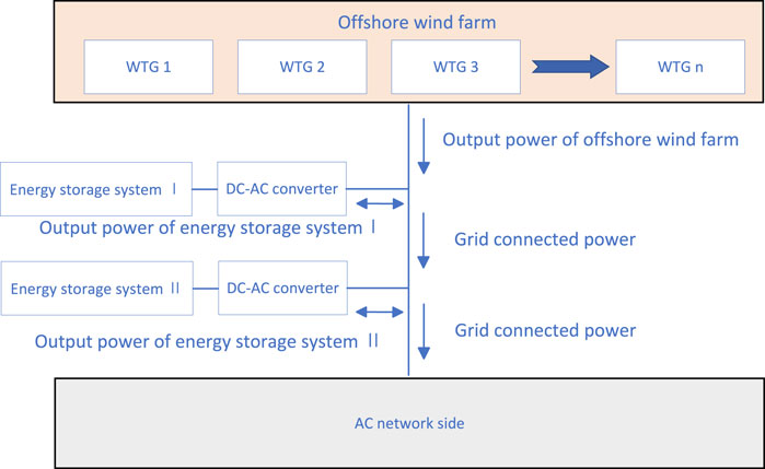
Figure 2. Structure diagram of offshore wind power generation side energy storage system.
2.1 MMC unit module topology
The structure of the sub unit module (Ji et al., 2021) is shown in Figure 3, which consists of a main bridge arm and a capacitor connected in parallel with it. The unit module is responsible for the power exchange between the two sides of the MMC, which directly affects the working state and operation performance of the converter station. where, The voltage output of the sub unit module is expressed as
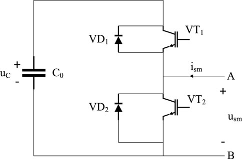
Figure 3. Unit module topology structure.
2.2 MMC main circuit topology
The three-phase modular MMC is a highly flexible and controllable multilevel converter topology (Rui et al., 2020b; Wang et al., 2024; Rui et al., 2020a), which is composed of several phase units with upper and lower bridge arms. MMC can achieve efficient energy conversion and transmission, and its multi-level structure can reduce power loss and improve energy efficiency. At the same time, it has high voltage control accuracy and response speed, and can quickly adjust the voltage level to deal with grid fluctuations, so as to improve the stability and anti-interference ability of the system. Its unique modular design makes the maintenance and repair of the system more convenient, reduces downtime and maintenance costs, and can increase the number of modules to expand the capacity and power output of the system in the face of power transmission of different sizes and demands. It can realize long-distance, large capacity power transmission, and can also be used for renewable energy access and scheduling, which has great application prospects and value. Figure 4 shows the main circuit topology of three-phase MMC (Sun et al., 2022).
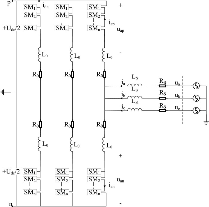
Figure 4. Unit module topology structure.
From Kirchhoff current law we get Equation 1:
where x = a, b, c. represent three-phase circuit respectively.
From Kirchhoff voltage law we get Equation 2:
where
Three phase modulation voltage can be expressed as Equation 3:
After dq rotation coordinate transformation, the three-phase modulation voltage can be expressed as Equation 4:
Combined with the above formula, the mathematical model of MMC unit module in the rotating coordinate system can be get as Equation 5:
where
The model is decomposed into two subsystems containing only positive sequence components and negative sequence components, which can be expressed as Equation 6:
The mathematical model of the converter in the rotating coordinate system can be obtained by park transformation for the subsystem with positive and negative sequence components:
Through Laplace transform, Equation 7 can be expressed as the frequency domain form of Equation 8:
where
To control the positive and negative sequence components of current respectively in the rotating coordinate system and reduce the interaction between them, PI control is used to decouple them. The decoupled expression is shown in Equation 9:
where:
When the voltage of each phase is unbalanced, there will be circulating current between phases. This is because the bridge arm structure of the input stage is symmetrical up and down, and the input current of each phase is divided equally by the upper and lower bridge arms, and the three-phase DC output terminal is connected in parallel to the medium voltage DC bus. The circulating current usually flows from the phase with higher voltage to the phase with lower voltage, and forms a closed loop through the medium voltage DC bus connected in parallel at the DC output.
The bridge arm current and the loop current can be expressed as Equations 10, 11 respectively:
where
The structure block diagram of MMC unit module in two-phase dq coordinate system is shown in Figure 5. The structure diagram of MMC control system (Huang and Chen, 2022) is as follows. It can be seen from the above Figure 6 that the object is the fundamental frequency component of each parameter in the rotating coordinate system, the outputs
where
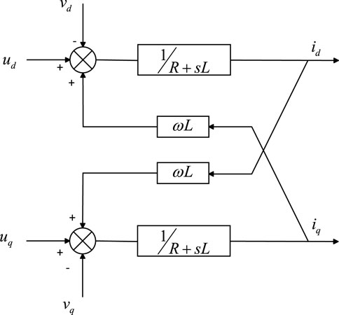
Figure 5. MMC structure diagram in rotating coordinate system.
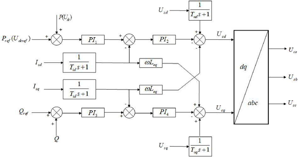
Figure 6. Structure diagram of control system based on dq transform.
2.3 MMC-MTDC AC/DC system model
DC system of flexible direct system based on MMC (Zhang et al., 2022) is mainly composed of DC transmission line, smoothing reactor and DC circuit breaker at the end of converter station. In this paper, R-L series model is used to equivalent DC transmission line. The model of a DC transmission line can be expressed as Equation 13.
where U1 and U2 are DC bus voltage of flexible direct transmission system, I is DC bus current of flexible direct transmission system, and L is equivalent reactance of DC bus of flexible direct transmission system.
In general, the AC system (Du et al., 2019) is composed of resistance, inductance, capacitance and other components in series, parallel or series parallel with each other. In this paper, Thevenin equivalent circuit is used to equivalent the AC system and establish the model, and the complex AC system is simplified to an equivalent circuit, including ideal power supply and equivalent impedance. All inductance and capacitance elements are converted to impedance form in complex frequency domain, and the impedance of all elements is added to obtain the equivalent impedance Z of the system. Then connect the ideal power supply and Z in series to form an equivalent circuit model. The Figure 7 shows the equivalent circuit diagram of AC system.
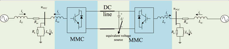
Figure 7. Equivalent circuit diagram of AC system.
2.4 Small signal modeling of MMC MTDC
Series parallel mode is a common MMC-mtdc topology, which is characterized by combining MMC modules in series and parallel to form a system with high voltage and high power capacity.
This section discusses in detail the state space model of multi terminal flexible direct transmission system based on MMC, which covers many components such as AC/DC system, main circuit and control system. The structure of the state space model is shown in Figure 8. Based on the linearization around the stable operating point, the mathematical model of small signal stability can be derived.
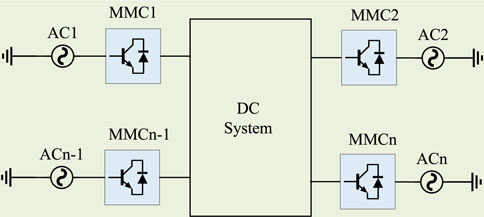
Figure 8. MTDC transmission system model based on MMC.
An AC transmission lines satisfies the differential Equation 14:
where
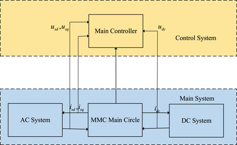
Figure 9. Flexible transmission system logic diagram.
A state-space MMC model based on the 12th order dynamic phase can be expressed as Equation 15:
where x is the state variable and u is the control input.
Based on the above theory, the dynamic vector state space model of MMC can be obtained by linear approximation at the stable operating point, which can be expressed as Equation 16:
where K is the state space matrix,
where
Output variables can be expressed as Equation 18:
where
MMC-mtdc system is composed of N converter stations. Its complete small signal model can be expressed as Equation 19:
where:
3 Verification of MTDC small signal model based on MMC
At present, the connection modes of MMC-MTDC system mainly include series connection and parallel connection. Taking the four terminal flexible direct transmission system as an example, the parallel topology is flexible, reliable, easy to maintain and expand, which is conducive to the regulation and operation of the whole system, so the system adopts the parallel topology. The selection of system parameters is shown in Table 1. Figure 10 shows the system topology.
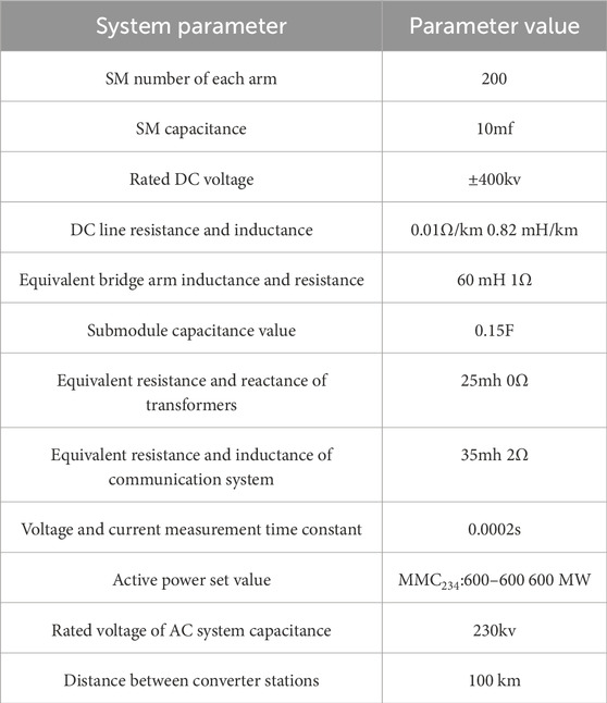
Table 1. MMC-MTDC system parameter selection.
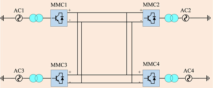
Figure 10. Structure diagram of transmission system based on MMC-MTDC.
In this topology, all converter stations have two-way transmission capability, which can realize two-way transmission of power. MMC1 and MMC3, as transmission converter stations, can convert AC power into DC power and input it into DC system. MMC2 and MMC4, as receiving converter stations, can convert DC power into AC power and transmit power to the corresponding AC system.
3.1 Simulation and verification of small signal model based on time domain
This section aims to verify the reliability and stability of the proposed small signal model. Matlab/Simulink software is used to simulate and verify the four terminal flexible direct transmission system described in Section 2.4.
Set the output active power value of converter station MMC2 to change from 600 MW to 640 MW in steps when t = 0.1 s. The dynamic response results of the established small signal model and the Simulink simulation model are shown in Figure 11. We can see that after being disturbed, the system starts to stabilize gradually after a certain time, and finally returns to the equilibrium state. The simulation results are very close to the dynamic response of the actual power system, indicating that the model has high accuracy and reliability.
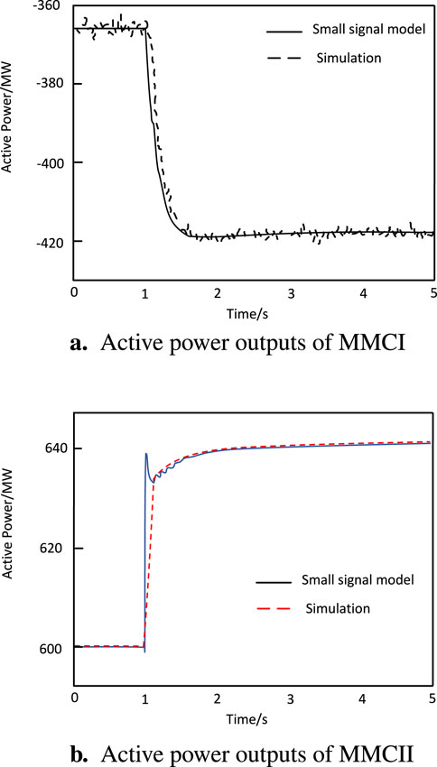
Figure 11. Dynamic response results of nonlinear model and small signal model. (A) Active power outputs of MMCI. (B) Active power outputs of MMCII.
3.2 Participation factor analysis and influence of control parameters
The eigenvalues of a linear system usually represent the response characteristics of the system. When the eigenvalues are on the left side of the imaginary axis, the stability of the system will be guaranteed, and the dynamic response of the system is convergent without divergence or oscillation. The eigenvalues of the above system are shown in Figure 12. The eigenvalues close to the imaginary axis have a greater impact on the dynamic response characteristics of the system.

Figure 12. Distribution of system eigenvalues.
The system participation factor (Iskakov, 2021) refers to the size of the dynamic response of each element in the power system to the system. Specifically, the system participation factor can be used to analyze the contribution degree of each component in the system, and can also be used to evaluate the stability of the system. By calculating the participation factor of each component, we can know the influence of the component on the stability of the system, so as to take corresponding measures for the component to improve the stability and reliability of the system. The impact correlation of participation factors is defined as Equation 20:
where:
In this paper, each state variable of MMC-MTDC system is divided into four groups, as shown in the table below. The four largest eigenvalues among all eigenvalues are analyzed by the participation factor, and the analysis results are shown in Figure 13. The results show that when the four maximum eigenvalues change, the oscillation frequency, convergence speed and steady-state response of the system change, and the stability margin is affected. Therefore, in order to achieve the best performance of the system under different conditions and effectively improve the characteristics of the system, it is necessary to study the influence of control parameters on eigenvalues.
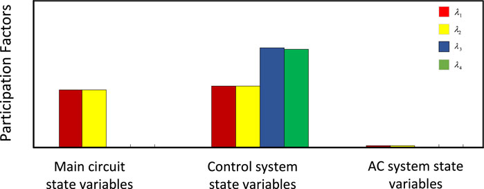
Figure 13. The maximum participation of the four eigenvalues.
3.3 Participation factor analysis and influence of control parameters
As the above control parameters will affect the system stability and stability margin, in order to improve the stability margin of MMC-MTDC system, this section first establishes the control parameter optimization method with the characteristic root as the objective function, and uses the optimization algorithm based on the sensitivity of control parameters to optimize multiple control parameters.
According to the above analysis, the MTDC system with N ports contains 18n-1 eigenvalues. When these 18n-1 eigenvalues are located in the left half of the complex plane, the stability of the system can be guaranteed. The real part of the eigenvalue can reflect the speed of the dynamic response of the system, and the eigenvalue nearest to the imaginary axis can reflect the stability margin of the studied system. If the eigenvalue closest to the virtual axis is far away from the virtual axis, the stability margin of the system is large and the system has strong stability to disturbance; On the contrary, if the eigenvalue closest to the imaginary axis is very close to the imaginary axis, it indicates that the stability margin of the system is small and the stability of the system to disturbance is weak.In order to improve the stability margin of the system, all eigenvalues should be kept away from the imaginary axis and on the leftmost side of the coordinate axis as far as possible. The system optimization model can be expressed as Equation 21:
where:
Step 1: small signal modeling of the system.
Step 2: solve the eigenvalues of the system state space matrix, and select the four eigenvalues closest to the virtual axis as the object of the optimization function.
Step 3: calculate the parameter sensitivity according to the optimization model, and establish the optimization control matrix
Step 4: determine the iteration step size in the optimization process by using the method based on Backtracking straight line search. The steps are shown in Figure 14. Of which
Step 5:adjust the control parameters of the system according to the output step t of the previous step, i.e.,
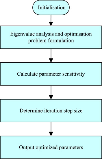
Figure 14. Flow chart of parameter optimization algorithm based on sensitivity.
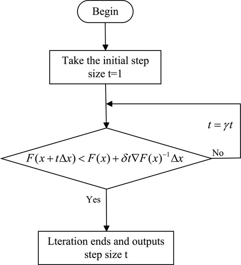
Figure 15. Steps of line search method based on Backtracking.
Termination condition:, where
4 Simulation verification
In this section, taking the flexible direct transmission system in Section 2.4 as an example, the stability evaluation and time-domain simulation are carried out in Matlab/Simulink software to verify the correctness and credibility of the proposed small signal model and the accuracy of the control parameter selection method.
4.1 Stability assessment
According to the above research results, the four maximum eigenvalues of the system state space matrix are optimized.According to Figure 16, with the increase of iteration times, the performance index g decreases, and the maximum four eigenvalues are far away from the imaginary axis. The optimized control system parameters make the system more stable.
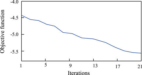
Figure 16. Objective function optimization process trajectory.
4.2 Time domain simulation
Simulation 1: when t = 1s, the setting of MMCI DC voltage reference is changed from
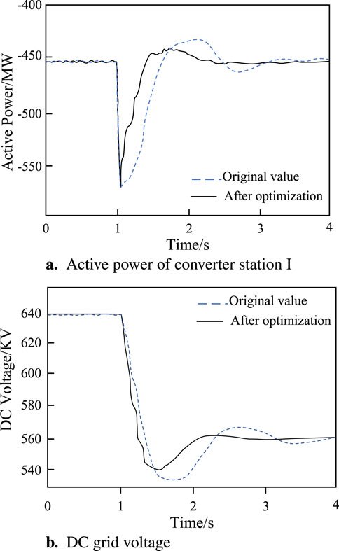
Figure 17. Dynamic response results of active power and DC voltage during MMCI DC voltage transition. (A) Active power of converter station I. (B) DC grid voltage.
Simulation 2: when t = 1 s, the MMC
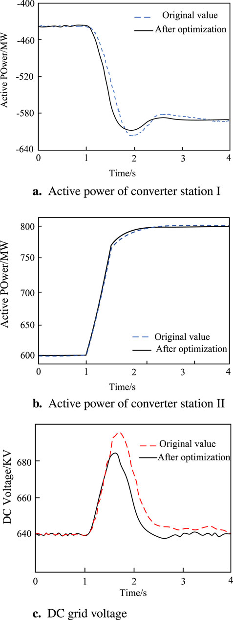
Figure 18. Change curve of active power and DC voltage when active power of MMC
Simulation 3: When t = 1 s, a resistive pole to pole short circuit fault of 20
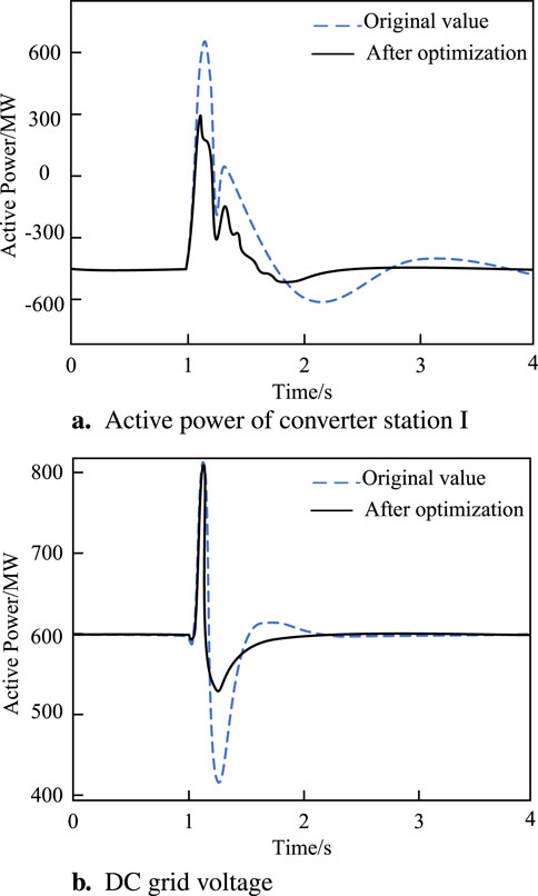
Figure 19. Active power response of system under short circuit fault. (A) Active power of converter station
The results of comprehensive stability evaluation and time-domain simulation show that the optimized control parameters improve the dynamic response speed of the four terminal flexible direct transmission system under large disturbance, the system can quickly perceive the external disturbance and accurately compensate the external disturbance, and reduce the transition time of the system. The proposed optimal control parameter design method is real and effective. This method can provide reliable stability guarantee for the design of MTDC system based on MMC, and improve the response speed and performance of the system. Therefore, this design method has important practical application value, and can provide guidance and reference for the control system design of MTDC system based on MMC.
5 Conclusion
Aiming at the stability problem of the modular multilevel converter-type multi-terminal flexible DC transmission system, which can easily lead to the change of the dynamic response within the grid due to the interaction of power allocation and voltage regulation between different converter stations, and the difficulty in selecting the control parameters, which leads to the insufficient stability margin of the system, this paper puts forward an optimization method of the control parameters. First, a small-signal model of the system is established and analyzed. Secondly, the backtracking line search method is used to determine the optimization step size, and the optimization algorithm with the eigenvalue as the optimization objective function is established. Finally, the four-terminal flexible DC transmission system is taken as an example for simulation verification. The results show that the proposed control parameter optimization algorithm can effectively improve the stability margin of the system, enhance the ability of the system to cope with various external perturbations and internal fluctuations, improve the robustness of the system and reduce vibration.
The practical significance of the results lies in the fact that the optimization of control parameters can not only improve the overall stability of the flexible DC transmission system, but also reduce the response time and fluctuation amplitude of the power grid when it encounters unexpected events or environmental changes. This is of great significance for the operation of the actual power system, because stability and reliability are key indicators in the modern power grid. The optimized system can better adapt to complex conditions such as renewable energy access and power market fluctuations to ensure the continuity and quality of power supply. In addition, the methodology provided in this study provides theoretical and practical references for the stability optimization of other similar power systems, which has high application value and promotion potential.
Data availability statement
The original contributions presented in the study are included in the article/supplementary material, further inquiries can be directed to the corresponding author.
Author contributions
JX: Data curation, Writing–original draft, Formal Analysis, Funding acquisition. JK: Investigation, Writing–original draft, Methodology, Project administration. WC: Formal Analysis, Writing–review and editing. YC: Conceptualization, Writing–original draft, Data curation, Formal Analysis. LD: Software, Writing–original draft, Supervision, Validation.
Funding
The author(s) declare that no financial support was received for the research, authorship, and/or publication of this article.
Conflict of interest
The authors declare that the research was conducted in the absence of any commercial or financial relationships that could be construed as a potential conflict of interest.
Publisher’s note
All claims expressed in this article are solely those of the authors and do not necessarily represent those of their affiliated organizations, or those of the publisher, the editors and the reviewers. Any product that may be evaluated in this article, or claim that may be made by its manufacturer, is not guaranteed or endorsed by the publisher.
References
Du, W., Fu, Q., and Wang, H. (2019). Open-loop modal coupling analysis for a multi-input multi-output interconnected mtdc/ac power system. IEEE Trans. Power Syst. 34, 246–256. doi:10.1109/TPWRS.2018.2857857
Fu, Y., Liu, Y., Huang, L.-l., Ying, F., and Li, F. (2022). Collection system topology for deep-sea offshore wind farms considering wind characteristics. IEEE Trans. Energy Convers. 37, 631–642. doi:10.1109/TEC.2021.3104040
Haegel, N. M., and Kurtz, S. R. (2022). Global progress toward renewable electricity: tracking the role of solar (version 2). IEEE J. Photovoltaics 12, 1265–1272. doi:10.1109/JPHOTOV.2022.3206532
Huang, T., and Chen, X. (2022). Sequence impedance modeling and optimization of mmc-hvdc considering dc voltage control and voltage feedforward control. ENERGIES 15, 9649. doi:10.3390/en15249649
Iskakov, A. B. (2021). Definition of state-in-mode participation factors for modal analysis of linear systems. IEEE Trans. Automatic Control 66, 5385–5392. doi:10.1109/TAC.2020.3043312
Ji, S., Huang, X., Palmer, J., Wang, F., and Tolbert, L. M. (2021). Modular multilevel converter (mmc) modeling considering submodule voltage sensor noise. IEEE Trans. Power Electron. 36, 1215–1219. doi:10.1109/TPEL.2020.3008524
Jiao, N., Wang, S., Ma, J., and Liu, T. (2021). Influencing factors of harmonic coupling in modular multilevel converter. IEEE Trans. Appl. Supercond. 31, 1–4. doi:10.1109/TASC.2021.3107820
Karwatzki, D., and Mertens, A. (2018). Generalized control approach for a class of modular multilevel converter topologies. IEEE Trans. Power Electron. 33, 2888–2900. doi:10.1109/TPEL.2017.2703917
Lee, J.-H., Park, S.-J., and Lim, S.-K. (2024). High-speed controller to enhance responsiveness and stability of dynamic characteristics for dc–dc converter. IEEE Trans. Industrial Electron. 71, 3996–4005. doi:10.1109/TIE.2023.3277086
Ma, C., Li, X., Wang, J., Wang, C., Duan, Q., and Wang, W. (2017). A comprehensive evaluation of microwave emissivity and brightness temperature sensitivities to soil parameters using qualitative and quantitative sensitivity analyses. IEEE Trans. Geoscience Remote Sens. 55, 1025–1038. doi:10.1109/TGRS.2016.2618903
Rong, F., Wu, G., Li, X., Huang, S., and Zhou, B. (2019). All-dc offshore wind farm with series-connected wind turbines to overcome unequal wind speeds. IEEE Trans. Power Electron. 34, 1370–1381. doi:10.1109/TPEL.2018.2834965
Rui, W., Qiuye, S., Dazhong, M., and Xuguang, H. (2020a). Line impedance cooperative stability region identification method for grid-tied inverters under weak grids. IEEE Trans. Smart Grid 11, 2856–2866. doi:10.1109/TSG.2020.2970174
Rui, W., Qiuye, S., Pinjia, Z., Yonghao, G., Dehao, Q., and Peng, W. (2020b). Reduced-order transfer function model of the droop-controlled inverter via Jordan continued-fraction expansion. IEEE Trans. Energy Convers. 35, 1585–1595. doi:10.1109/TEC.2020.2980033
Shahriari, E., Gruson, F., Vermeersch, P., Delarue, P., Colas, F., and Guillaud, X. (2020). A novel dc fault ride through control methodology for hybrid modular multilevel converters in hvdc systems. IEEE Trans. Power Deliv. 35, 2831–2840. doi:10.1109/TPWRD.2020.2998535
Song, Y., and Breitholtz, C. (2016). Nyquist stability analysis of an ac-grid connected vsc-hvdc system using a distributed parameter dc cable model. IEEE Trans. Power Deliv. 31, 898–907. doi:10.1109/TPWRD.2015.2501459
Sun, P., Tian, Y., Pou, J., and Konstantinou, G. (2022). Beyond the mmc: extended modular multilevel converter topologies and applications. IEEE Open J. Power Electron. 3, 317–333. doi:10.1109/OJPEL.2022.3175714
Sun, P., Wang, Y., Khalid, M., Blasco-Gimenez, R., and Konstantinou, G. (2023). Steady-state power distribution in vsc-based mtdc systems and dc grids under mixed p/v and i/v droop control. Electr. Power Syst. Res. 214, 108798–108810. doi:10.1016/j.epsr.2022.108798
Wang, D., Cheng, D., Sun, X., Chen, W., Qiao, F., Liu, X., et al. (2023). Novel travelling wave directional pilot protection approach for lcc-mmc-mtdc overhead transmission line. Int. J. Electr. power energy Syst. 144 (10), 108553. doi:10.1016/j.ijepes.2022.108553
Wang, R., Sun, Q., Hu, W., Li, Y., Ma, D., and Wang, P. (2021). Soc-based droop coefficients stability region analysis of the battery for stand-alone supply systems with constant power loads. IEEE Trans. Power Electron. 36, 7866–7879. doi:10.1109/TPEL.2021.3049241
Wang, R., Yu, X., Sun, Q., Li, D., Gui, Y., and Wang, P. (2024). The integrated reference region analysis for parallel dfigs’ interfacing inductors. IEEE Trans. Power Electron. 39, 7632–7642. doi:10.1109/TPEL.2024.3361091
Wang, Y., Liao, S., Xu, Q., Wang, L., and Guerrero, J. M. (2022). Coordinated design of control parameters for improving interactive and internal stability of mmc-hvdc. Int. J. Electr. power energy Syst. 140, 108065. doi:10.1016/j.ijepes.2022.108065
Wen, X., Peng, J., Aziz, S., and Jiang, H. (2020). Pcc voltage compensation scheme of mmc-mtdc system for transient stability enhancement under communication delay. IEEE Access 8, 187713–187720. doi:10.1109/ACCESS.2020.3026097
Wu, W., Wu, X., and Jing, L. (2020). Active damping control of multi-port dc power flow controller for suppressing power oscillation of mmc-mtdc under unbalanced grid. 3436–3441. doi:10.1109/ECCE44975.2020.9236277
Wu, Z., and Guo, X. (2024). Novel coordinated control strategy for step-up/down current-source converter. IEEE Trans. Industrial Electron. 71, 3264–3274. doi:10.1109/TIE.2023.3274857
Xiang, H., Lei, B., Li, Z., Zhao, K., Lv, Q., Zhang, Q., et al. (2015). Analysis of parameter sensitivity of induction coil launcher based on orthogonal experimental method. IEEE Trans. Plasma Sci. 43, 1198–1202. doi:10.1109/TPS.2015.2404439
Yang, Q., Chen, Y., Lin, Y., Chen, X., and Wen, J. (2023). Pi consensus-based integrated distributed control of mmc-mtdc systems. IEEE Trans. Power Syst. 38, 2333–2347. doi:10.1109/TPWRS.2022.3179530
Yi, W., Zhang, Y., Zhao, Z., and Huang, Y. (2018). Multiobjective robust scheduling for smart distribution grids: considering renewable energy and demand response uncertainty. IEEE Access 6, 45715–45724. doi:10.1109/ACCESS.2018.2865598
Yu, D., Zhang, W., Chu, Z., Zhang, H., and Wang, Z. (2023). An optimized synchronous approach to dc/dc droop backstepping control considering voltage compensation in dc microgrids. Electr. POWER Syst. Res. 228, 110014. doi:10.1016/j.epsr.2023.110014
Zhang, H., Wang, X., Mehrabankhomartash, M., Saeedifard, M., Meng, Y., and Wang, X. (2022). Harmonic stability assessment of multiterminal dc (mtdc) systems based on the hybrid ac/dc admittance model and determinant-based gnc. IEEE Trans. Power Electron. 37, 1–1665. doi:10.1109/TPEL.2021.3103797
Keywords: modular multilevel controller, multi terminal DC transmission system, parameter selection, stability analysis, offshore wind farms
Citation: Xiaotong J, Kezheng J, Chenyu W, Chang Y and Dan L (2024) MMC parameter selection and stability control for flexible direct transmission converter station of energy storage power station. Front. Energy Res. 12:1445383. doi: 10.3389/fenrg.2024.1445383
Received: 07 June 2024; Accepted: 26 August 2024;
Published: 06 September 2024.
Edited by:
Tianyang Zhao, Royal Institute of Technology, SwedenReviewed by:
Wei Hu, Hunan University, ChinaZhangjie Liu, Central South University, China
Bingyu Wang, North China Electric Power University, China
Copyright © 2024 Xiaotong, Kezheng, Chenyu, Chang and Dan. This is an open-access article distributed under the terms of the Creative Commons Attribution License (CC BY). The use, distribution or reproduction in other forums is permitted, provided the original author(s) and the copyright owner(s) are credited and that the original publication in this journal is cited, in accordance with accepted academic practice. No use, distribution or reproduction is permitted which does not comply with these terms.
*Correspondence: Wang Chenyu, MjM3MTAwOUBzdHUubmV1LmVkdS5jbg==