 Ruifeng Wang1,2
 Ke Zhu
 Wei Ren
- 1The 4th Geological Team of Hebei Geology and Mining Bureau, Chengde, China
- 2Hebei Key Laboratory of Mountain Geological Environment, Chengde, China
- 3The 6th Geological Team of Hebei Geology and Mining Bureau (Center for Applied Aeronautical Survey of Hebei Geology and Mining Bureau), Shijiazhuang, China
- 4National Coal Mine Water Hazard Prevention Engineering Technology Research Center, China University of Mining and Technology, Beijing, China
- 5Xinkai Environment Investment Co., Ltd., Beijing, China
- 6Institute of Comprehensive Survey for Natural Resources, China Geological Survey, Beijing, China
- 7Longhua County Water Affairs Bureau, Chengde, China
The Double U-pipe ground heat exchanger, known for its simple process, cost-effectiveness, high heat exchange efficiency, and low thermal resistance, remains the predominant type of ground heat exchanger in today’s shallow geothermal energy development and utilization. In recent years, significant research has focused on the factors influencing heat transfer and the heat exchange performance of Double U-pipe ground heat exchangers through experimental testing methods. However, studies that integrate numerical simulation with in situ testing have been less common. Utilizing the cylindrical heat source model theory and the results of regional in situ thermal response tests, this paper develops a Double U-pipe ground heat transfer model by establishing physical, mathematical, and heat transfer geometric models. It evaluates the effects of varying inlet temperatures, flow rates, and initial ground temperatures on heat exchange efficiency under heating conditions. The results confirm the accuracy of the Double U-pipe ground heat exchanger model based on in situ testing. They indicate that increasing the temperature differential between the inlet and initial temperatures, raising the initial ground temperature, and moderately enhancing the flow rate can improve the system’s heat exchange efficiency.
1 Introduction
Shallow geothermal energy is the heat stored in rocks, soil, groundwater, and surface water up to a depth of 200 m from the Earth’s surface. It is valued for its high efficiency and eco-friendliness. China possesses substantial shallow geothermal resources, with major cities holding approximately 2.78 × 10²⁰ J, and the exploitable resource estimated at 2.89 × 10¹² kwh (Lin et al., 2013). Ground source heat pump systems are the primary means for harnessing shallow geothermal energy, including the ground-coupled and groundwater heat pump systems. The ground-coupled system, known for its environmental benefits, energy efficiency, reliable operation, and longevity, promises wide-ranging future applications. This system operates by embedding high-density polyethylene (HDPE) pipes in the subsurface, where a circulating fluid (water) within the pipes serves as a heat transfer medium. This fluid exchanges heat with the surrounding rocks and soil, conveying the absorbed heat to the heat pump unit. Here, the heat pump’s reverse Carnot cycle transforms the low-grade heat to a high-grade heat source. Research on ground-coupled heat exchangers focuses on analyzing the heat transfer process and identifying key influencing factors. Liu et al. (2014) have performed in situ thermal response tests to examine the effects of testing and data processing techniques on outcomes; Zhang (2020) has thereby enhancing the heat transfer law and influential factors of ground-coupled pipes under layered and seepage conditions. Li, (2022) conducted numerical simulations on mid-deep buried pipes to investigate their heat transfer properties and optimize operational parameters, thus improving the heat exchange efficiency of the buried pipe heat exchangers. Wang et al. (2019) employed numerical simulation techniques to examine the heat transfer characteristics and efficiency of underground heat exchangers with buried pipes across various geological layers, suggesting that intermittent operation could prevent cold accumulation. While Yang (2023) analyzed the factors influencing the heat exchange system using test data. Additionally, Wang et al. (2023) examined the impact of backfill materials and burial depth of ground-coupled pipes on the heat exchange system through OGS numerical simulation. In the development and utilization of shallow geothermal energy, Zhang et al. (2022), Cao et al. (2022), and Cao et al. (2023) examined the application of phase change materials in ground heat exchangers (GHEs) for the storage and exchange of cold and heat energy in engineering contexts, such as high-temperature tunnel cooling and precast high-strength concrete energy piles. Li et al. (2024) and Zhang et al. (2022) respectively explored the heat transfer performance of shallow coaxial geothermal heat exchangers and medium-depth U-tube heat pump systems.
Currently, there are primarily two types of heat transfer models for vertical ground-coupled heat exchangers recognized both domestically and internationally: the analytical solution model based on line heat source theory and the numerical solution model for cylindrical heat source (Zhou, 2016). Over 30 heat transfer models for buried pipe heat exchangers have been developed, validated through experimental and numerical simulation methods. The infinite line heat source model, foundational to this area, originates from the line heat source theory introduced by Kelvin in 1882. Subsequently, Ingersoll and Jamieson developed a model based on this theory for an infinitely large medium (Ingersoll et al., 1950; Ingersoll et al., 2009). This model is ideal for scenarios with small pipe diameters, sufficient burial depth, and thermal stability, but less so for ground-coupled heat exchangers with significant thermal capacity (Eskilson, 1987; Bose et al., 1985; Fang et al., 2002). As research has progressed, this methodology has been extensively applied to analyze heat transfer in ground-coupled heat exchangers, incorporating complex factors to enhance model accuracy (Hart and Couvillion, 1986).
Carslow initially proposed the cylindrical surface heat source model (Carslow et al., 1986). In 1985, Kavanaugh enhanced this model by introducing a more practical engineering-aligned cylindrical heat source model (Kavanaugh, 1985). For practical calculations, this model accounts for the uneven heat flux density and internal thermal resistance within the pipe, as well as the thermal interactions between double U-pipes, thereby yielding more accurate calculation results (Zeng, 2017; Yu, 2016).
This article examines the double U-pipe ground heat exchanger configuration. Utilizing in situ testing, it develops a model for the heat exchange between the double U- pipe ground heat exchanger and the adjacent rock-soil mass. It simulates the effects of the heat exchanger on the surrounding rock-soil mass during operation, analyzes the spatiotemporal dynamics of the underground heat exchanger, identifies the primary factors influencing its heat exchange, and examines the operational characteristics of the underground heat exchanger.
2 Heat transfer model
2.1 Theoretical analysis of double U-pipe ground heat transfer
2.1.1 Heat transfer process of double U-pipe ground heat transfer
The heat exchange in a double U-pipe ground heat exchanger primarily involves a complex, multi-level process with the surrounding rock-soil mass. It consists of five main parts: convective heat exchange between the circulating fluid inside the double U-pipe and the walls of the double U-pipe PE pipes; heat conduction between the PE pipe’s inner and outer walls; thermal conduction from the PE pipe’s outer wall to the fine sand in the backfill material; heat conduction within the fine sand; and the heat transfer process from the fine sand to the surrounding rock-soil mass. During system operation, the heat exchange between the fluid inside the pipe and the pipe wall is forced convection, while it transitions to natural convection during intermittent periods. The backfill material and the surrounding soil primarily exchange heat through the porous medium and pore water, involving both heat conduction and convection.
2.1.2 Heat transfer model of double U-pipe ground heat exchanger
Based on the theory of cylindrical heat source, a model is established with the following assumptions:
(1) The heat transfer around the buried pipe is only radial between the rock-soil mass.
(2) The seepage of water in the rock-soil mass is not considered.
(3) There is no thermal interference from nearby pipe wells.
(4) The soil is regarded as an infinitely large medium.
For the case of constant heat flow, the formula for the temperature field distribution around the cylindrical heat source of the heat exchanger in the surrounding rock-soil mass is:
Where r is the distance between any point and the buried pipe, m; t is the operating time of ground source heat pump system, s; T0 is the original temperature of undisturbed rock-soil mass, °C; q is the heat flow of line heat source, that is, the heat transfer per unit length, W/m; λ is the thermal conductivity of soil, W/(m K);
Where J0, J1 is the zeroth and first order Bessel functions of the first kind, respectively; γ0, γ1 is the zeroth and first order Bessel functions of the second kind, respectively;
According to Kavanaugh’s research findings, the average temperature of the fluid inside the pipe is as follows (Kavanaugh, 1992; Du and Chen, 2010):
Where Tf is the average temperature of the fluid inside the pipe, °C; r0 is the borehole radius; r1 is the U-pipe radius; N is the number of buried pipe wells; C is the heat flow correction coefficient; heq is the overall thermal conductivity coefficient outside the pipe, W/(m·°C);
2.2 Geologic setting and in-situ testing of the study area
2.2.1 Geologic setting of the study area
The research site is situated in the northeast of Chengde City, Hebei Province, China, within the Yanshan mountain region of northern Hebei. The area is characterized by relatively thin Quaternary sediments in the valleys, while the bedrock is predominantly exposed. It falls within a severely cold climate zone according to building thermal engineering zoning. The regional geological formation mainly consists of Archean gneiss and other metamorphic rocks, overlaid by Mesozoic continental basins. These basins have a complete sequence ranging from the Lower Jurassic to the Lower Cretaceous, with a cumulative thickness exceeding 6,600 m. The test borehole revealed the strata in descending order as follows: sand gravel (0–2.10 m), gravelly subclay (2.10–14.52 m), Jurassic sandstone (14.52–20.00 m), conglomerate (20.00–55.51 m), andesite (55.51–105.47 m), and Archean gneiss (105.47–200 m) (Zhu et al., 2022). The borehole’s stratigraphic structure is illustrated in Figure 1.
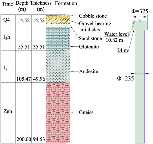
Figure 1. Stratigraphic structure diagram of the test borehole (Zhu et al., 2022).
2.2.2 Thermal properties of rocks and characteristics of the geothermal field
The analysis of borehole samples and regional geotechnical samples collected recently reveals that various lithologies and structural formations significantly differ in their physical properties. Additionally, the thermal properties of rocks and soils exhibit distinct variations. The specific heat capacity values, arranged from lowest to highest, are as follows: gneiss < sandstone < conglomerate < andesite < sand < sandy subclay; the thermal conductivity values, ordered from lowest to highest, are: conglomerate < sandy subclay < sandstone < sand < andesite < gneiss. This data indicates that, compared to bedrock, the sand and soil layers in Quaternary sediments possess a higher specific heat capacity. However, their thermal conductivity (thermal conductance) is generally lower than that of the bedrock layers. Among the bedrock layers, the primary materials exhibiting higher thermal conductivity and thermal diffusivity are predominantly Archean metamorphic rocks. Refer to Table 1 for detailed information.
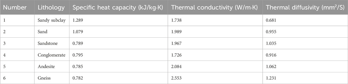
Table 1. Characteristics of the thermal physical properties of rocks and soils in test boreholes.
The shallow geothermal field encompasses the vertical variation and planar distribution characteristics of ground temperature up to 200 m beneath the surface. It is typically segmented into three layers: the variable temperature layer, the constant temperature layer, and the increasing temperature layer. Geothermal monitoring data has facilitated the creation of line charts depicting the variations in ground temperature with depth at various times. As illustrated in Figure 2, the geothermal gradient within 200 m beneath the test borehole area is approximately 1.76°C per 100 m. The top 25 m is designated as the variable temperature layer, where ground temperature exhibits significant fluctuations in response to changes in air temperature. The constant temperature layer spans from 25 to 40 m, characterized by minimal temperature variation with depth. Below 40 m lies the increasing temperature layer, where ground temperature progressively rises in a nearly linear fashion with increasing depth.
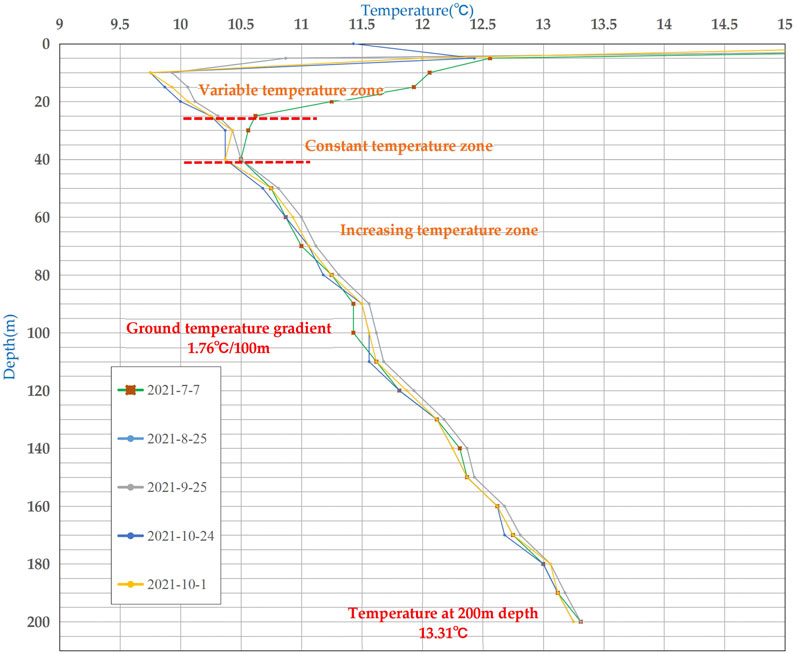
Figure 2. Variations in subsurface temperature at various depths and times within the borehole.
2.2.3 In-Situ thermal response test
This study utilizes the constant temperature method for thermal response testing to evaluate the heat exchange efficiency of a double U-pipe ground heat exchanger under various operational conditions, by conducting a comparative analysis of the experimental outcomes. The test borehole is equipped with a double U-pipe ground heat exchanger, made of high-density polyethylene (HDPE) tubing. The tubing’s installation involves both manual and mechanical techniques, with the heat exchange tubes being filled with water and the pressure kept at 0.5–0.6 MPa to prevent deformation or twisting of the PE tubes. To accurately represent the geothermal field’s characteristics under the initial and heat exchange conditions of the test borehole, a vertical temperature measuring cable is installed adjacent to the heat exchanger. This cable has temperature measurement points every 5–10 m, enabling the real-time monitoring of ground temperature data.
The constant temperature method for thermal response testing can document the operational characteristics of the heat exchanger under real operating conditions (Figure 3). The parameters of the heat exchanger include: the electric heater has a range of 36 kW, adjustable; the water chilling unit has a range of 24 kW, adjustable; the circulating pump has a range of 1–12 m³/h, adjustable, with a maximum head of 30 m; the power sensor has a range of 0–30 A, with an accuracy of class 1.0; the temperature sensor has a range of −50 to +100°C, with an accuracy of ±0.15°C; the flow sensor has a range of 0–12 m³/h, with an accuracy of class 0.5; the pressure transducer has a range of 0–1.6 MPa, with an accuracy of 10 Pa.
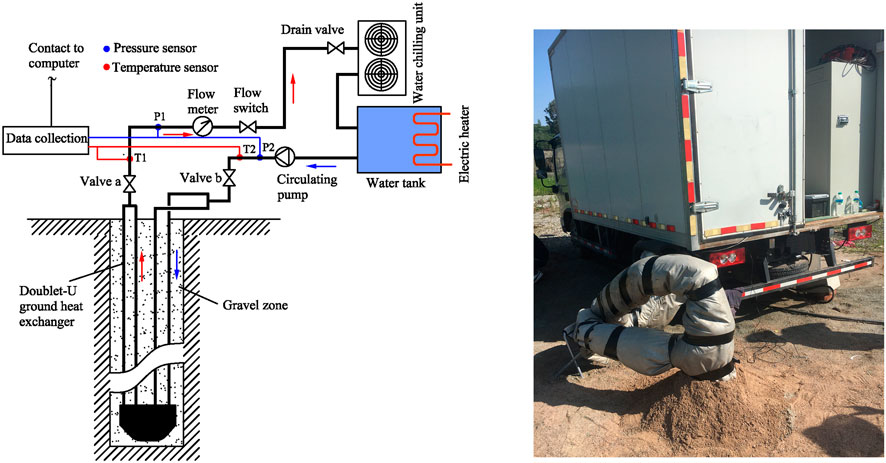
Figure 3. Thermostatic thermal response test devices (Zhu et al., 2022).
When the heat exchanger operates in heating (or cooling) mode, the heat transfer medium is heated (or cooled) by the equipment and then circulated at a fixed constant temperature through the heat exchanger tubes. Concurrently, thermal convection facilitates heat exchange between the medium and the surrounding rock-soil. By monitoring the flow and temperature of the circulating medium, the heat exchange capacity of the medium is determined and translated into the overall heat exchange rate of the borehole and the heat exchange rate per meter. As illustrated in Figure 4, in the heat discharge scenario, the outlet water temperature (the difference between inlet and outlet temperatures) of the double U-pipe ground heat exchanger is 26.1°C (8.1°C), resulting in a calculated heat exchange rate of 17.01 kW per borehole and 84.79 W/m per meter, with a heat transfer coefficient of 23.75; in the heat absorption scenario, the outlet water temperature (the difference between inlet and outlet temperatures) of the double U-pipe ground heat exchanger is 7.2°C (3.2°C), resulting in a calculated heat exchange rate of 6.11 kW per borehole and 30.45 W/m per meter. with a heat transfer coefficient of 26.12.
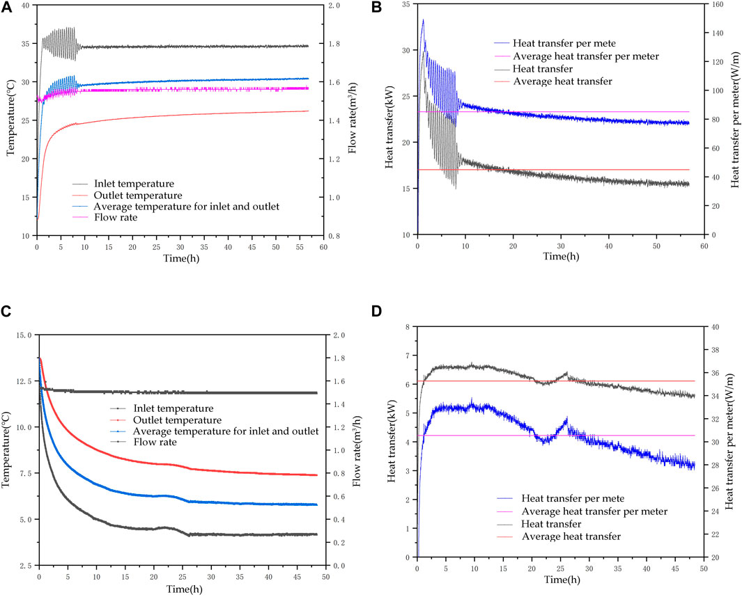
Figure 4. Thermal Response Test Results under Different Operating Conditions: (A). Temperature and flow rate curves of inlet and outlet water over time under heat rejection conditions (Zhu et al., 2022); (B). Heat transfer and average power curves over time under heat rejection conditions; (C). Temperature and flow rate curves of inlet and outlet water over time under heat extraction conditions; (D). Heat transfer and average power curves over time under heat extraction conditions.
2.3 Establishment of the double U-pipe ground heat exchanger model
2.3.1 Physical model
This article draws on in situ tests and numerical simulation conducted on double U-pipe ground heat exchangers. It primarily aims to investigate the parameters influencing the heat exchange efficiency of underground heat exchangers and the variations in the temperature field surrounding the borehole. To simplify the model and the simulation experiment, groundwater seepage in the study area is disregarded, enabling a clearer illustration of the intricate multi-level heat exchange process between the heat exchanger and the adjacent rock-soil mass. Consequently, this article presents the physical model of the double U-pipe ground heat exchanger as depicted in Figure 5. For the purpose of simplifying the heat exchanger model for easier computation, the following assumptions are made: ① The thermal contact resistance between the pipes and backfill material, as well as between backfill material and stratum soil, is overlooked; ② The soil’s homogeneity and thermal properties are considered constant; ③ The impact of moisture migration within the soil is excluded; ④ The interaction between boreholes is disregarded; ⑤ The surface temperature’s influence on the soil temperature is ignored, ensuring a uniform temperature distribution in the soil surrounding the model; ⑥ The heat transfer in the radial direction around the U- pipe through the rock-soil mass is not considered, with heat transfer occurring only in the axial and radial directions; ⑦ The temperature and flow rate of the fluid at any given interface inside the vertical pipe are assumed to be uniform.
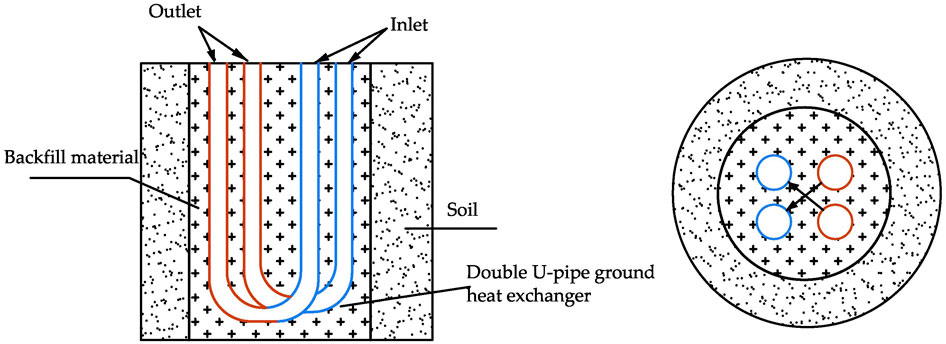
Figure 5. Physical Model of double U-pipe ground heat exchanger.
2.3.2 Mathematical model
2.3.2.1 Control equations
Focusing on the double U-pipe ground heat exchanger as the subject of study, we establish a mathematical model to describe the heat exchange between the surrounding rock mass and the heat exchanger, as illustrated in Figure 6. The heat exchange process is notably complex, and the simulation conducted using FLUENT software adheres to the conservation laws of energy, mass, and momentum.
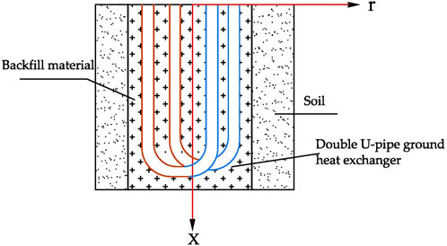
Figure 6. Mathematical Model of double U-pipe ground heat exchanger.
The continuity equation is expressed as:
Where ρ is the density of fluid inside the pipe, kg/m³; U is the velocity vector; u, ν, ω is the flow velocities corresponding to the three orthogonal coordinate directions, m/s; x, y, z is the three directions of the Cartesian coordinate system.
The energy equation is expressed as:
Where T is the soil temperature, K; k is the permeability of porous media; Cp is the specific heat at constant pressure of the soil, kJ/kg·°C; ST is viscous dissipation term, the heat source in the fluid and thermal energy that converted from mechanical energy of viscous acting fluids. Its expression can be found in reference (Versteeg and Malalasekera, 1995).
The momentum equation is formulated as follows: Fluid flow must adhere to the principle of momentum conservation. This law yields equations in three orthogonal coordinate directions (Wang, 2004). The formulas for the x, y, and z directions are represented as follows:
Where n is the velocity vector; p is the pressure on a fluid cell;
Where
2.3.2.2 Boundary conditions
In the theoretical framework of the model discussed, the earth is assumed to be an infinitely large entity, with the influence of the subterranean pipe heat exchanger on the rock-soil mass extending indefinitely. However, in practical engineering scenarios, the effect of the subterranean pipe heat exchanger on the adjacent rock-soil mass diminishes as the distance increases. This study focuses on monitoring the temperature variations within the borehole and its immediate soil environment. Given that the model’s scale is directly proportional to the actual experimental dimensions at a 1:1 ratio, and considering the extensive computational demand due to a high number of grids, the model’s diameter is designated as 2 m, with the borehole depth fixed at 200 m. The z-axis is the main axis of the borehole. This boundary condition applies to functions of the buried pipe distance r and the running time t. The assumption of initial conditions and boundary conditions:
Where
Initial parameter configurations are derived from thermal response test outcomes, indicating an initial ground temperature of 12.1°C. Additional parameters, including soil density, type of rock layer, and thermal conductivity, are established based on experimental findings.
2.3.3 Heat transfer geometric model
Previous researchers have utilized the equivalence method to approximate the double U-pipe as a cylindrical heat source model. This approach aligns the cylindrical coordinates with the geometric shape of the mathematical model, thereby simplifying the mathematical description and solution of the ground pipe model. In this study, Workbench software is employed to create the heat transfer geometric model of the double U-pipe (Figure 7). Based on the thermal properties of different strata rock types presented in Table 2, the model is segmented into modules, merging pebbles and gravel stone into one layer, and sandstone and conglomerate into another. The thermal parameters for various rock-soil mass layers are calculated using the weighted average value.
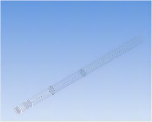
Figure 7. Model diagram.
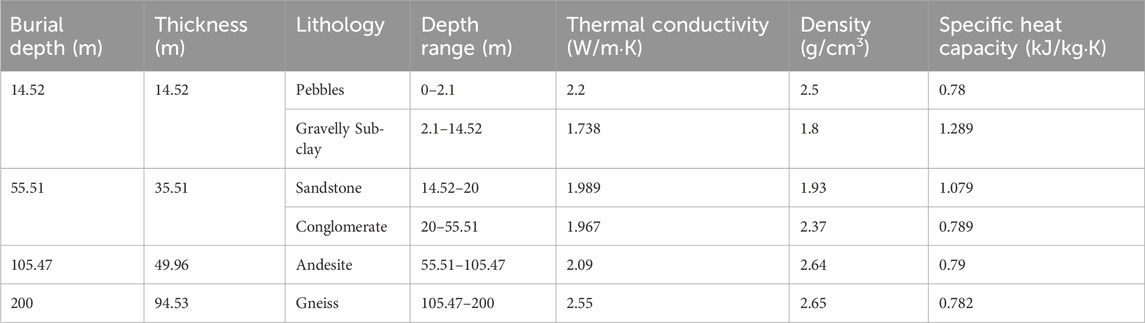
Table 2. Thermal properties of different formation lithologies.
Building on the geometric model of the double U-pipe ground source heat pump exchanger, a heat transfer model is developed. To facilitate the simulation calculation, the bottom of the double U-type heat exchanger is connected and arranged in a cross shape in this model, which as depicted in Figure 8 for simplification. This configuration minimizes the heat exchange impact of the inlet pipe on the outlet pipe fluid, thereby enhancing the heat exchange efficiency.

Figure 8. Model diagram of the connection U-pipe.
2.3.4 Mesh division of heat transfer model
This paper utilizes Fluent for fluid simulation, enabling the analysis of physical quantities like velocity, pressure, temperature, and concentration within the flow field at different locations and their temporal variations. It incorporates grid support technologies such as grid adaptation, multi-grid initialization, and polyhedral mesh to model both compressible flow and incompressible flow, two-dimensional or three-dimensional fluid flows, inviscid or viscous flows, laminar or turbulent flows, and natural or forced convection heat transfer.
The numerical simulation process in Fluent involves four stages: establishing the mathematical model, selecting the computational method, conducting iterative calculations, and visualizing the results. Initially, the model is segmented into grids. This paper utilizes Workbench to launch the model and interface with Fluent for grid segmentation. Grid segmentation is classified into unstructured and structured types. The benefit of structured segmentation is its grid quality independence from grid quantity, making it ideal for regular geometric models; however, unstructured segmentation suits irregular models despite requiring more grids (Zhao, 2017; Li et al., 2004; Gu et al., 2006; Tang et al., 2006; Zhu, 2013). Given the slender design of the double U-pipe ground heat exchanger and the significantly larger volume of backfill material and soil compared to the buried pipe, the model necessitates numerous grids without the need for excessive precision. Thus, unstructured grid segmentation is chosen, with the segmentation outcomes illustrated in Figure 9.
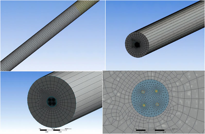
Figure 9. Model meshing.
The fluid region comprises three physical structures: the inlet pipe, the outlet pipe, and the elbow pipe. Correspondingly, the U-pipe ground heat exchanger region consists of three independent structures. Both the backfill area and the soil area contain two independent structures each. During the simulation experiment, a mesh quality verification was conducted for this model division, achieving an effective mesh unit of 98.56%, which indicates good mesh quality. By combining the flow velocity and pipe diameter parameters outlined in this paper, it is determined that the state is turbulence, based on the Reynolds number.
2.4 Boundary conditions
2.4.1 Definition of boundary types
The model presented in this paper is segmented into three components: drilling, soil, and circulating fluid, with the fluid categorized as “fluid” and the remaining two as “solid.” The model’s boundary types are defined as the inlet surface for the circulating fluid, the drilling surfaces, the ground heat exchanger, the lateral sides of the soil, and their respective upper and lower surfaces. The inlet and outlet interfaces of the ground heat exchanger are designated as velocity inlet and free outflow, respectively, with all other boundaries classified as “wall.”
2.4.2 Boundary model parameters
Before running the simulation calculations, configure the model parameters, including the thermophysical properties of the backfill material, pipe thermal parameters, and inlet and outlet temperatures. The foundation of the model delineated in this paper is based on an in situ test, with water being the chosen circulating fluid in the ground heat exchanger, under the assumption of constant water parameters. The heat exchanger is constructed from PE pipe, and medium-fine sand is the selected backfill material. A set of operational condition parameters chosen for this study is detailed in Table 3.
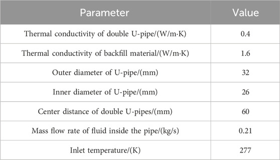
Table 3. Setting of basic parameters.
2.4.3 Boundary condition settings
In defining the boundary conditions, the fluid inlet boundary is segmented into inlet flow velocity and temperature. This study, alongside the previously mentioned experiments, models the heat extraction process by quantitatively setting the flow rate and velocity, with an inlet temperature of 4°C. The fluid outlet boundary is automatically configured by Fluent software to have a flowrate weighting of 1. The heat exchange at the ground pipe wall boundary, involving both the backfill material and the circulating fluid within the ground pipe, is designated as a coupled surface, with the pipe wall thickness specified at 6 mm. Regarding fluid properties, water is characterized by a specific heat capacity of 4.2 × 10³ J/kgK, thermal conductivity of 0.6 W/mK, and a density of 1,000 kg/m3. The drilling side surface, interacting thermally with both the inner backfill material and the outer rock-soil, is also treated as a coupled surface. The boundary condition at the drilling’s bottom is established with a constant initial ground temperature of 12.1°C. The upper surface of the rock-soil thermal energy system employs convection heat transfer, with the convection coefficient and outdoor air temperature set accordingly. The side and bottom surfaces of the soil maintain a constant temperature of 12.1°C. The soil mass extends to 200 m, with the thermal properties of each rock layer determined based on experimental outcomes.
3 Results and discussion
This article examines and compares the calculated outlet temperature with the experimental outlet temperature, drawing on thermal response test results from an in situ test of a double U-pipe ground heat exchanger. The tests maintain consistent geometric and condition parameters, thereby validating the model’s accuracy. Under simulated heating conditions, a controlled variable method is employed to independently alter the inlet temperature of the circulating fluid, the inlet flow rate, and the initial ground temperature. This approach aims to investigate variations in outlet temperature, heat exchange efficiency, and the temperatures of the surrounding rock-soil mass during operation.
3.1 Model validation
To assess the model’s precision, this study performs a simulation based on the thermal response test of a double U-pipe ground heat exchanger, maintaining the geometric and condition parameters nearly identical. The system is simulated to operate for 50 h, and the resulting outlet temperature is compared with the experimental outlet temperature, as depicted in Figure 10. The temperature change trend in the simulation aligns closely with that observed in the experiment. However, a notable discrepancy exists between the two within the first 5 h of operation, attributed to the constant temperature method employed in the actual thermal response test. During this period, the temperature fluctuates, exhibiting a higher inlet temperature, whereas the simulation maintains a steady 4°C, leading to a marked difference in outlet temperature and divergent trends. By considering the temperature after 5 h for difference calculation, the average discrepancy is found to be less than 6.3%. To simplify calculations and model development, and to minimize the grid count, similar geological layers are combined, and the necessary thermal property parameters are derived using weighted averages, thereby introducing some variance between the simulation outcomes and experimental data. Furthermore, primarily due to the impact of temperature parameters, the actual inlet temperature of the ground pipe varies dynamically, differing from the constant value used in the simulation. Consequently, a 6.3% error margin is deemed acceptable, affirming the model’s accurate validation.
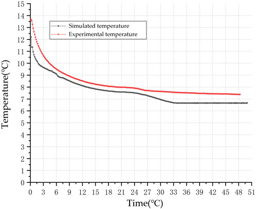
Figure 10. Outlet temperature variation curve.
3.2 The impact of inlet temperature on the Heat Exchange Characteristics of heat exchangers
The inlet temperatures were set at 4°C, 6°C, and 8°C, respectively, to simulate the outlet temperature and heat exchange rate (Figure 11). The findings show that the outlet temperature varies with the inlet temperature, initially decreasing at an increased rate before gradually stabilizing at a certain value. As the inlet temperature rises, the benefit of the temperature differential between the fluid inside the pipe and the surrounding rock of the heat source well for heat exchange lessens. This is evidenced by a significantly smaller gradient in the outlet temperature change under these conditions, along with the lowest heat exchange rate. Upon analyzing the heat exchanger’s performance at the 120th h, the heat exchange rates at 4°C, 6°C, and 8°C were recorded as 15.52 kW, 11.74 kW, and 7.96 kW, respectively. An increase in the inlet temperature from 4°C to 6°C resulted in a 24.35% decrease in the heat exchange rate; a further increase to 8°C led to a 48.7% reduction. During winter, raising the inlet temperature of the underground pipes adversely affects heat exchange due to the diminished initial temperature difference with the surrounding soil. According to Fourier’s law, a lower temperature difference equates to a weaker driving force for heat conduction, thus reducing the heat exchange rate. Therefore, in practical engineering applications, enhancing the temperature difference between the inlet and the initial temperature during winter can improve the heat exchanger’s rate, beneficial for decreasing the heat exchange capacity and enhancing the efficiency of the underground heat exchanger.
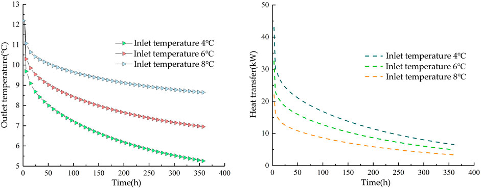
Figure 11. Impact of different inlet temperatures on heat exchange characteristics: (A) Impact on outlet temperature; (B) impact on heat exchange rate.
The simulation of temperature distribution around the heat source well at the 240th h of operation of the heat exchanger, under varying inlet temperatures, is depicted through temperature distribution contour maps (Figure 12). These maps utilize a legend to represent temperatures in absolute temperature K. The findings indicate that the ground temperature surrounding the heat exchanger, with an inlet temperature of 4°C, is lower than that at 8°C, exhibiting an average temperature difference of 2°C at identical locations. It is posited that employing a low-temperature fluid as the circulating working substance exerts a more significant impact on the adjacent rock-soil mass, and the extent of the cold front’s influence is broader. Consequently, reducing the inlet temperature to augment the temperature differential between the fluid and the rock-soil mass enhances the heat exchange rate to some degree. Nonetheless, this approach may lead to the accumulation of cold at the borehole’s upper section, thereby diminishing the outlet temperature. Prolonged operation could escalate the operational burden on the heat pump unit, diminishing its efficiency.
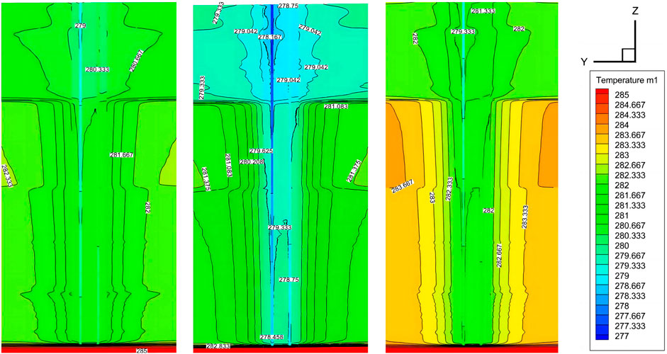
Figure 12. Temperature contour at 240 h while Different Inlet Temperatures: (A) Tin = 4°C; (B) Tin = 6°C; (C) Tin = 8°C; (D) legend.
3.3 The impact of initial ground temperature on the Heat Exchange Characteristics of heat exchangers
By adjusting the initial ground temperatures to 9.2°C, 12.2°C, and 15.2°C, and maintaining the inlet temperature at 4°C while keeping other variables constant, this study explores the effects of varying initial ground temperatures on the outlet temperature and the heat exchange rate of the heat pipe (Figure 13). The findings reveal a direct correlation between the initial ground temperature and the variations in the outlet temperature and heat exchange rate, with the highest values for both parameters recorded at an initial ground temperature of 15.2°C. At 120 h of operation, the outlet temperatures for initial ground temperatures of 12.2°C, 9.2°C, and 15.2°C were 6.96°C, 5.88°C, and 8.04°C, respectively. The lowest initial ground temperature demonstrated temperature differences of 1.08°C and 2.16°C when compared to the other two settings, suggesting that a 3°C rise in initial ground temperature could lead to an average increase of 1.08°C in the outlet temperature. The respective heat exchange rates were 15.52, 9.84, and 21.2 kW. Starting from an initial ground temperature of 9.2°C, a 3°C increase resulted in a 57.7% rise in heat exchange rate within 3 h, while a 6°C increase yielded a significant 115.4% surge in heat exchange rate. Therefore, it is clear that maintaining a constant inlet temperature while increasing the initial ground temperature boosts the efficiency of the heat exchanger. In the context of winter heating, regions with higher initial ground temperatures demonstrate greater heat exchanger efficiency, potentially allowing for a reduction in the required heat exchanger capacity during the design phase.

Figure 13. Different initial ground temperatures affect the outcome: (A) Outlet temperature changes; (B) Different Heat transfer changes.
Simulation of the ground temperature field characteristics around the heat exchanger after 240 h of operation, under varying initial ground temperatures, demonstrated that an initial ground temperature of 15.2°C significantly impacted the upper rock-soil mass layers more than 9.2°C (Figure 14). This was due to a greater initial temperature difference with the inlet fluid at the start of the heat exchange process. This larger temperature difference served as a stronger driving force for heat exchange, leading to a more rapid and intense heat transfer. Therefore, in practical engineering operations, for regions with higher initial ground temperatures, adjusting the inlet temperature is crucial to optimize heat exchange and prevent heat accumulation in the upper layers.
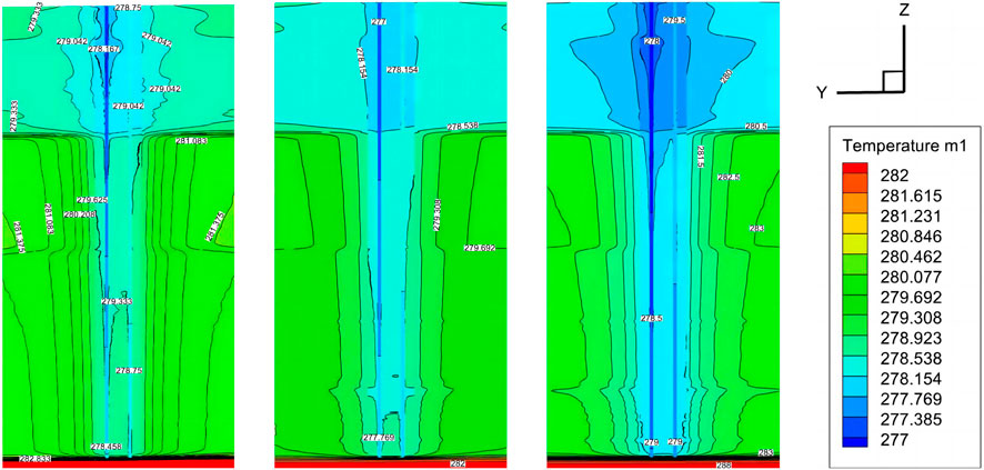
Figure 14. Temperature cloud maps formed from different initial ground temperatures: (A) Initial ground temperature 12.2°C; (B) Initial ground temperature 9.2°C; (C) Initial ground temperature 15.2°C; (D) legend.
3.4 Impact of inlet flow on the heat transfer characteristics of heat exchangers
In this model, with the inlet temperature maintained at a constant 4°C, an increase in inlet flow rate results in a decrease in outlet temperature, thus diminishing the temperature differential between the inlet and outlet (Figure 15). Upon analyzing the operation at 120 h, the outlet temperatures for inlet flow rates of 0.75 m³/h, 1 m³/h, and 1.5 m³/h were observed to be 6.94°C, 6.37°C, and 5.66°C, respectively. The temperature difference between 0.75 m³/h and the other two rates was 0.57°C and 1.28°C, respectively, corresponding to a reduction in outlet temperature by 8.2% and 18.4%. It is posited that increasing the fluid velocity inside the pipe diminishes the heat exchange duration between the fluid and the surrounding rock-soil mass, leading to a decrease in outlet temperature. The flow rate’s impact on the heat exchange rate initially increases and then diminishes, with the turning point occurring after 250 h, where the heat exchange rate at 1.5 m³/h is lower than at 0.75 m³/h. This is attributed to the fact that, at the onset of operation, the temperature of the rock-soil mass around the heat exchanger is higher, and an increase in flow rate, to a certain degree, enhances the heat exchange rate. As the system continues to operate and the temperature of the rock-soil mass around the heat exchanger drops, a “high flow rate, low temperature difference” phenomenon emerges. A high flow rate leads to a shorter residence time in the pipe, gradually diminishing the heat exchange rate; conversely, a lower flow rate results in a slower fluid velocity, longer heat exchange duration, and a higher heat exchange rate compared to a high flow rate. Therefore, increasing the flow rate can enhance the heat exchange rate up to a certain point, but with diminished heat exchange efficiency; beyond a specific value, the heat exchange performance may be less effective than that of a lower flow rate operation.
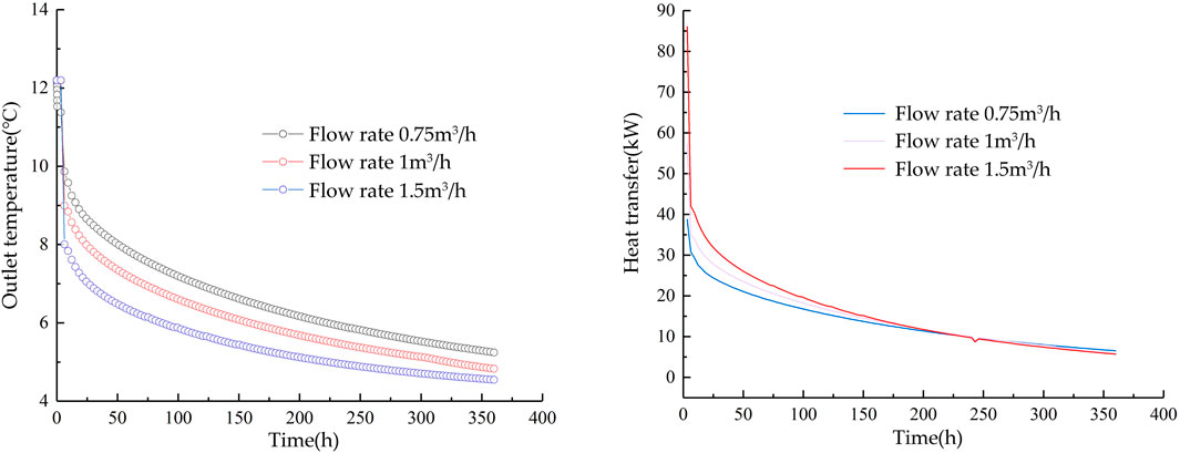
Figure 15. Effects of Different Flow Rates: (A) Impact of different flow rates on outlet temperature; (B) Impact of different flow rates on heat exchange rate.
Simulation of ground temperature field characteristics after 270 h of operation under varying inlet flow rates reveals that changes in flow rates within the pipe result in different thermal response times and temperature differences between the surrounding rock-soil mass and the fluid temperature (Figure 16). A moderate increase in flow rate can improve heat exchange efficiency, but a significant increase results in a quicker reduction in the temperature of the surrounding rock-soil mass, thereby decreasing heat exchange efficiency over extended operation. In practical engineering applications, it is recommended to increase the flow rate moderately.
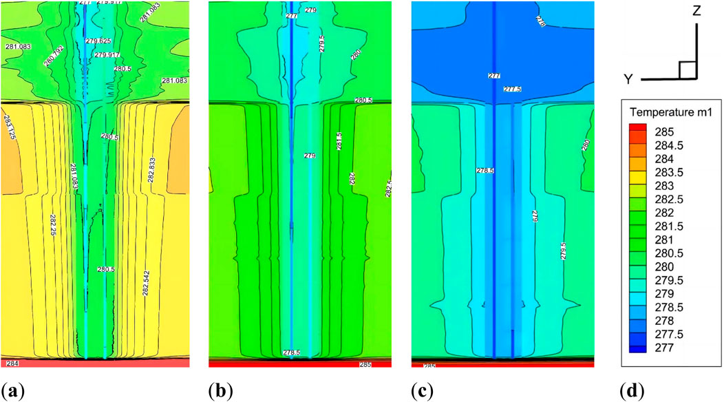
Figure 16. Temperature Contour Maps Formed by Different Inlet Flow Rates: (A) Inlet flow rate of 0.75 m³/h; (B) Inlet flow rate of 1 m³/h; (C) Inlet flow rate of 5 m³/h; (D) legend.
4 Conclusion
This study investigates the influence of a double U-pipe ground heat exchanger on the temperatures of the surrounding rock-soil mass, as well as the impact of variations in relevant parameters on the heat exchange properties. This is achieved by simulating the heat exchange process of the exchanger. The conclusions are as follows:
1. Changing the inlet temperature directly influences heat exchange efficiency. In winter, a 2°C change in inlet temperature leads to a 24.35% reduction in heat exchange amount; when the change rises to 4°C, the heat exchange amount decreases by 48.7%, significantly affecting heat exchange efficiency.
2. The initial ground temperature shows a positive correlation with both the heat exchange rate and the outlet temperature. An increase of 3°C in the initial ground temperature can elevate the outlet temperature by 1.08°C, and the heat exchange rate within 3 h by 57.7%; a 6°C rise can boost the outlet temperature by 2.16°C, enhancing the heat exchange rate by 115.4%.
3. Moderately increasing the inlet flow rate can improve the heat exchange rate, but maintaining a too high flow rate over an extended period can result in a “high flow rate, small temperature difference” scenario, which adversely affects the system’s heat exchange.
4. Long-term operation of the heat exchanger will lead to the accumulation of cold/heat in the surrounding rock-soil mass, reducing the efficiency of heat exchange. The upper part of the heat exchanger is where problems first occur and are most serious.
Data availability statement
The original contributions presented in the study are included in the article/supplementary material, further inquiries can be directed to the corresponding author.
Author contributions
RW: Conceptualization, Writing–review and editing. MS: Methodology, Writing–review and editing. KZ: Software, Writing–review and editing. JY: Formal Analysis, Writing–review and editing. WR: Validation, Writing–review and editing. GY: Project administration, Writing–review and editing. ZY: Writing–original draft. SG: Resources, Writing–review and editing.
Funding
The authors declare that financial support was received for the research, authorship, and/or publication of this article. This research was supported by the following projects: S&T Program of Chengde (Project No. 202008F024); the key R&D projects of resources and environment in Hebei Province (Project No. 20374207D); S&T Program of Hebei (Project No. 215A9904D); the National Natural Science Foundation of China (Grant No. U2344227).
Acknowledgments
We would like to express our gratitude to Chengbing Zhang from the Hebei Bureau of Geological and Mineral Resources Exploration for the technical guidance and assistance he provided during this research.
Conflict of interest
Author KZ was employed by Xinkai Environment Investment Co., Ltd.
The remaining authors declare that the research was conducted in the absence of any commercial or financial relationships that could be construed as a potential conflict of interest.
Publisher’s note
All claims expressed in this article are solely those of the authors and do not necessarily represent those of their affiliated organizations, or those of the publisher, the editors and the reviewers. Any product that may be evaluated in this article, or claim that may be made by its manufacturer, is not guaranteed or endorsed by the publisher.
References
Bose, J. E., Parker, J. D., and McQuiston, F. C. (1985). Design/data manual for closed-loop ground coupled heat pump systems. United States: Oklahoma State Univ. Stillwater.
Cao, Z., Zhang, G., Liu, Y., Xu, Z., and Chenglin, Li (2022). Influence of backfilling phase change material on thermal performance of precast high-strength concrete energy pile. Renew. Energy 184, 374–390. doi:10.1016/j.renene.2021.11.100
Cao, Z., Zhang, G., Wu, Y., Yang, J., Sui, Y., and Xu, Z. (2023). Energy storage potential analysis of phase change material (PCM) energy storage units based on tunnel lining ground heat exchangers. Appl. Therm. Eng. 235, 121403. doi:10.1016/j.applthermaleng.2023.121403
Carslow, H. S., Jaeger, J. C., and Morral, J. E. (1986). Conduction of heat in solids. 2nd edn. London, United Kingdom: Oxford University Press.
Du, C., and Chen, Y. (2010) “Improved model of finite length line heat source for vertical buried pipes,” in Proceedings of the national HVAC&R academic annual conference 2010. Hangzhou, China, November 9, 2010.
Fang, Z., Diao, N., and Cui, P. (2002). Discontinuous operation of geothermal heat exchangers. Tsinghua Sci. Technol. 02, 194–197.
Gu, Z., Wu, Y., Tang, Z., and Ma, Z. (2006). Numerical simulation of unsteady heat transfer in U-tube underground heat exchange systems. J. Eng. Thermophys. 02, 313–315. doi:10.3321/j.issn:0253-231X.2006.02.043
Hart, D. P., and Couvillion, R. (1986). Earth-coupled heat transfer: offers engineers and other practitioners of applied physics the information to solve heat transfer problems as they apply to earth-coupling. Ohio, United States: National Water Well Association.
Ingersoll, L. R., Adler, F. T., Plass, H. J., and Ingersoll, A. C. (1950). Theory of earth heat exchangers for the heat pump. Heat. Pip. Air Cond. 22, 113–122.
Ingersoll, R. L., Zobel, J. O., and Ingersoll, C. A. (2009). Heat conduction with engineering, geological, and other applications. Phys. Today. 8, 17. doi:10.1063/1.3061951
Kavanaugh, S. P. (1985) Simulation and experimental verification of vertical groundcoupled heat pump systems. PhD Thesis. Oklahoma (United States): Oklahoma State University, 2–9. doi:10.1002/(SICI)1099-114X(19970625)21:8<707::AID-ER274>3.0.CO
Kavanaugh, S. P. (1992). Field test of a vertical ground-coupled heat pump in Alabama. ASHRAE Trans. 98, 607–615.
Li, C. (2022). Heat exchange characteristics and operating parameter optimization of mid-deep geothermal energy building heating ground source heat exchanger. PhD Thesis. Xi’an (China): Chang’an University. doi:10.26976/d.cnki.gchau.2022.000088
Li, W., Jiakui, Xu, Chen, Y., and Chen, Z. (2024). Heat transfer performance and optimal design of shallow coaxial ground heat exchangers. Appl. Therm. Eng. 250, 123571. doi:10.1016/j.applthermaleng.2024.123571
Li, X., Jun, Z., and Qian, Z. (2004). Numerical simulation of soil temperature around a group of U-shaped vertical buried pipe heat exchangers. Acta Energ. Sol. Sin. 25, 703–707. doi:10.3321/j.issn:0254-0096.2004.05.028
Lin, W., Liu, Z., Wang, W., and Wang, G. (2013). The assessment of geothermal resources potential of China. Geol. China 01, 312–321. doi:10.3969/j.issn.1000-3657.2013.01.021
Liu, C., Wang, G., Wang, W., and Lin, W. (2014). Analysis of underground rock and soil thermal properties based on field thermal response test method. J. Jilin Univ. (Earth Sci. Ed.) 05, 1602–1608. doi:10.13278/j.cnki.jjuese.201405203
Tang, Z., Xiaoyan, S., Huang, J., and Wang, X. (2006). Numerical simulation of U-tube underground heat exchangers for ground source heat pumps. J. Beijing Univ. Technol. 1, 62–66. doi:10.3969/j.issn.0254-0037.2006.01.013
Versteeg, H. K., and Malalasekera, W. (1995). An introduction to computational fluid dynamics: the finite volume method. New York, NY: John Wiley and Sons Inc.
Wang, D., Han, T., and Xin, Ai (2023). Numerical simulation study on influencing factors of ground source heat exchanger. Jilin Geol. 02, 96–106118. doi:10.3969/j.issn.1001-2427.2023.02.015
Wang, F. (2004). Computational fluid dynamics analysis - principles and applications of CFD software. Beijing, China: Tsinghua University Press.
Wang, W. (2019). Study on heat transfer characteristics and heat exchange efficiency evaluation of layered formation vertical ground source heat exchangers. PhD Thesis. Beijing (China): China University of Geosciences. doi:10.27492/d.cnki.gzdzu.2019.000052
Yang, Y. (2023). Test on key influencing factors of GSHP ground source heat exchanger in Xi’an area. Chin. Coal Geol. 10, 58–62. doi:10.3969/j.issn.1674-1803.2023.10.10
Yu, G. (2016). Numerical analysis and research on the pipe diameter of dual U-shaped ground source heat pump ground buried pipes in a lianyungang project. Master’s thesis. Nanjing (China): Nanjing Normal University.
Zeng, F. (2017). Study on heat exchange performance of vertical buried pipe ground source heat pumps and ground temperature field simulation. Master’s Thesis. Nanjing (China): Nanjing Normal University.
Zhang, D. (2020) Study on heat transfer characteristics of vertical ground source heat exchangers under stratified and percolation conditions. PhD Thesis. Beijing (China): China University of Mining and Technology.doi:10.27623/d.cnki.gzkyu.2020.001811
Zhang, G., Cao, Z., Xiao, S., Guo, Y., and Chenglin, Li (2022). A promising technology of cold energy storage using phase change materials to cool tunnels with geothermal hazards. Renew. Sustain. Energy Rev. 163, 112509. doi:10.1016/J.RSER.2022.112509
Zhao, X. (2017). The impact of groundwater seepage on heat exchange of ground source heat pump buried pipes and soil. Master’s Thesis. Beijing (China): Beijing University of Civil Engineering and Architecture.
Zhou, Z. (2016) Study on vertical buried pipe system of ground source heat pump in severe cold regions. Master’s Thesis. Daqing (China): Northeast Petroleum University.
Zhu, J. (2013). Study on heat transfer characteristics of vertical ground buried pipe heat exchangers for soil source heat pumps. Master’s Thesis. Yangzhou (China): Yangzhou University.
Keywords: in-situ testing, double U-pipe ground heat exchanger, heat transfer model, shallow geothermal energy, numerical simulation
Citation: Wang R, Shi M, Zhu K, Yu J, Ren W, Yan G, Yin Z and Gao S (2024) Research on the heat transfer model of double U-pipe ground heat exchanger based on in-situ testing. Front. Energy Res. 12:1442185. doi: 10.3389/fenrg.2024.1442185
Received: 01 June 2024; Accepted: 16 August 2024;
Published: 29 August 2024.
Edited by:
Francesco Liberato Cappiello, University of Naples Federico II, ItalyReviewed by:
Marcello Iasiello, Università degli Studi di Napoli Federico II, ItalyZiming Cao, Southeast University, China
Copyright © 2024 Wang, Shi, Zhu, Yu, Ren, Yan, Yin and Gao. This is an open-access article distributed under the terms of the Creative Commons Attribution License (CC BY). The use, distribution or reproduction in other forums is permitted, provided the original author(s) and the copyright owner(s) are credited and that the original publication in this journal is cited, in accordance with accepted academic practice. No use, distribution or reproduction is permitted which does not comply with these terms.
*Correspondence: Ke Zhu, emh1a2ViajAzMDZAMTYzLmNvbQ==