 Yi Lu1
 Gang Shi
- 1Electric Power Research Institute of State Grid Zhejiang Electric Power Corporation, Hangzhou, China
- 2Department of Electrical Engineering, Shanghai Jiao Tong University, Shanghai, China
As the penetration of the integrated intermittent and fluctuating new energy (e.g., wind and photovoltaic power) increases, the conventional grid-following voltage source converter (VSC)-based high voltage direct current (HVDC) transmission system faces the problem of interactive instability with the grid. A novel grid-forming control strategy is proposed to overcome these issues, which adopts the dynamics of a DC capacitor to realize the function of self-synchronization with the grid. Moreover, the per-unit DC voltage can automatically track the grid frequency, acting as a phase-locked loop. Next, the small-signal model of the grid-forming VSC-HVDC system is established, and the stability of the system is analyzed using the eigenvalue analysis method and the complex power coefficient method. In addition, the stabilization controller is proposed for the grid-forming (GFM) control structure, which further enhances the grid-forming VSC-HVDC system’s stability and helps it operate stably under both stiff and weak grid conditions. Research results show that the VSC-HVDC system under the proposed grid-forming control can work stably in both stiff and weak grids. The grid-forming VSC-HVDC system is robust and can maintain stable operations with a large range variation of the parameters in the current and voltage control loop. Simulations are carried out on the PSCAD/EMTDC platform to verify the proposed grid-forming control strategy.
1 Introduction
In recent years, new energy sources, including wind and photovoltaic power, have developed rapidly in response to the energy crisis (Liu et al., 2024). The proportion of new energy integrated into the grid and the proportion of power electronic converters in the power system have been continuously increasing (Ma et al., 2024). The renewable energy-based power system is forming a “dual high” development trend (Zhang et al., 2023). At the same time, the power grid tends to exhibit weak grid characteristics (Sang et al., 2018; Zhu et al., 2020), which can cause problems such as low inertia and abnormal interaction phenomena (Wu Q. et al., 2019), posing severe challenges to the stability of renewable power generation.
The VSC-based high voltage direct current (HVDC) system is an effective way to solve the transmission issues of high-ratio new energy. As a key component of the HVDC system, the control strategy of the VSC plays a significant role in ensuring system stability and the quality of output power. At present, the control modes of grid-connected VSCs mainly include the grid-forming (GFM) control and the grid-following (GFL) control (Zhang et al., 2021). Under these two control modes, the grid-connected VSCs reflect the external characteristics of the current source and voltage source, respectively (Zhang et al., 2023; Pawar et al., 2021). The conventional VSC adopts the GFL control strategy, where the phase-locked loop (PLL) is employed to measure the voltage phase in the point of common connection (PCC) and adjust the output current to control the grid-connected power. However, due to the abnormal interference between the PLL and the grid’s impedance, the interactive stability margin of the grid-connected VSC gradually decreases with the reduction of the short-circuit ratio (SCR), triggering oscillation instability. Wang et al. (2020) and Wang et al. (2019) noted that the dynamic coupling between the PLL and grid impedance occurs under weak grid conditions, and the coupling degree will exacerbate with the increase of the PLL’s bandwidth. To improve the stability of the GFL VSC, Huang et al. (2022) present a voltage regulation control strategy that improves the synchronous operating performance of GFL VSC by automatically adjusting the input of PLL. Shao et al. (2021) proposed a modified design method of the PLL’s parameters to reduce the negative impact of PLL dynamics under weak grid conditions.
Compared with the GFL VSC, the VSC under the GFM control has better stability in a weak grid (Fu et al., 2021). Unlike the GFL strategy, the GFM control strategy does not need PLL and realizes the autonomous synchronization with the grid according to the power or DC-link voltage synchronization principle. The GFM control strategies mainly include the virtual synchronous generator (VSG) control, the droop control, and the matching control (Pan et al., 2020). Meng et al. (2019) proposed a generalized droop control strategy, where the inverter can offer virtual damping and virtual inertia without large overshoot and oscillation by adding an auxiliary controller. In addition, Meng et al. (2019) also noted that the generalized droop control can be equivalent to the droop control or VSG control strategy by adjusting the parameters. Aiming at the problem of low inertia and lacking frequency fluctuation caused by the renewable energy integration, Zha et al. (2021) adopted the electric torque model to analyze the inertia support characteristics and the system stability and noted that the VSC had better inertia support characteristics under the generalized droop control. Ge et al. (2023) established the model of the VSG-based VSC, and the support effect of VSG-based VSC was deeply studied with different inertia parameters. The sequence impedance model of VSG-based VSC was built and compared with that of the conventional VSC by Wu W. et al. (2019) through the harmonic linearization method, and the analysis results indicated the VSG-based VSC’s sequence impedance is essentially the same as the grid impedance, which means the VSG-based VSC is more stable than the conventional VSC under weak grid conditions. Li et al. (2022) analyzed the voltage and frequency stability of VSG-based VSC by establishing the small-signal model and proposed an improved control method to enhance the inertia and damping. However, these above droop and VSG control strategies Wu W. et al. (2019), Meng et al. (2019), Pan et al. (2020), Zha et al. (2021), Li et al. (2022), and Ge et al. (2023) take the active power as control targets and are applicable to grid-connected VSCs with stable and controllable motive power. With respect to the receiving end converter (REC), that is, the grid-connected VSC in the HVDC transmission system with intermittent and fluctuating input motive power, it is still essential to investigate a novel GFM control strategy with the DC-side voltage as the control target.
Recently, a kind of GFM control method with the DC-side voltage as the control objective has been proposed. A GFM control method called inertia synchronization control (ISynC) was presented by Sang et al. (2019) based on the matching principle between the DC voltage and the synchronous generator (SG). In Shao et al. (2019a) and Shao et al. (2019b), the ISynC-based GFM control strategy was applied to the doubly fed induction generator (DFIG)-based wind turbine, which makes the DC-side voltage track the grid frequency instantaneously, thus, the inertia response of the DFIG-based wind turbine can be achieved. Yang et al. (2018) utilized the ISynC-based GFM control method in the VSC-HVDC system, and the frequency tracking capability was useful in realizing the function of inertia support. Moreover, in Yang et al. (2020), the ISynC-based GFM control method was further expanded to the multi-port VSC-HVDC, which was able to establish the DC grid based on the droop control. Nevertheless, there is no current control loop in the ISynC-based GFM VSC (Shao et al., 2019a; Shao et al., 2019b; Sang et al., 2019), which cannot limit the output current and is not conducive to practical engineering applications.
Oriented to the VSC-HVDC transmission system with intermittent and fluctuating input motive power, a novel GFM control method taking the DC-side voltage as the control target is proposed in this article, which has the function of autonomously synchronizing the grid. The internal current control loop is added to the GFM structure; thus, the function of limiting the output current can be achieved, which makes the proposed GFM control strategy suitable for practical engineering applications. The GFM VSC-HVDC’s small-signal model is built, and the stability of the system is analyzed using the eigenvalue analysis method and the complex power coefficient method. In addition, the stabilization controller is proposed for the GFM control structure, which further enhances the GFM VSC-HVDC’s stability and helps it operate stably under both stiff and weak grid conditions.
2 Configuration of VSC-HVDC and grid-forming control
2.1 System configuration
Figure 1 presents the configuration of the VSC-HVDC transmission system, where renewable energy (e.g., wind farm) is integrated into the sending-end converter (SEC). The DC line is between the SEC and the REC, the voltage of the DC-side equivalent capacitor is udc, the SEC is integrated into the utility grid via an LC filter, and Rd is the damping resistor.
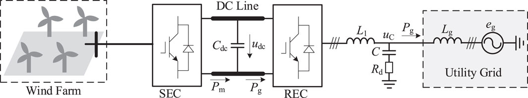
Figure 1. Configuration of the VSC-HVDC transmission system.
As seen in Figure 1, the dynamic equation of the REC’s capacitor voltage can be expressed in Eq. 1 as
where
The REC’s output active power
where
With respect to SG in the grid, the motion equation of the rotor is represented in Eq. 3 as
where
The SG’s input active power
where
Comparing (1) with (3) shows that the dynamical equation of the REC’s capacitor voltage is similar to the motion equation of the SG’s rotor. According to the similarity principle, the analogy relationship between the REC and the SG can be obtained, as shown in Figure 2. Comparing (2) with (4), the REC’s per-unit modulation voltage amplitude
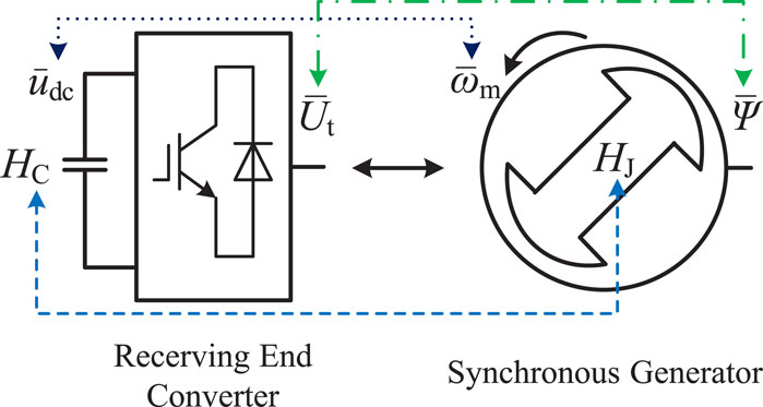
Figure 2. Matching relationship between the REC and the SG.
2.2 Grid-forming control strategy
The control target of the presented grid-forming control method is the converter’s DC-side voltage. Currently, according to different control objectives, existing grid-forming control methods can be divided into two groups, namely, the GFM control under the active power control mode and the GFM control under the DC-side voltage control mode. The VSG control belongs to the GFM control under the active power control mode, which is suitable for scenarios with a controllable input source, such as energy storage. Different from the VSG control, the proposed GFM control takes the DC voltage as the control objective, which is suitable for the two-stage conversion scenario with intermittent and fluctuating input motive power.
Figure 3 gives the VSC-HVDC system’s grid-forming control structure, where the REC adopts the grid-forming control strategy with three cascaded loops, and the SEC utilizes the conventional two cascaded loops. The REC takes the DC-side voltage and the reactive power as the control objectives. In the REC’s control diagram, the DC-side voltage of the REC passes through an integrator whose gain is the rated value of the grid’s angular frequency ωBg, and the output is the phase θ of the REC’s modulation voltage.
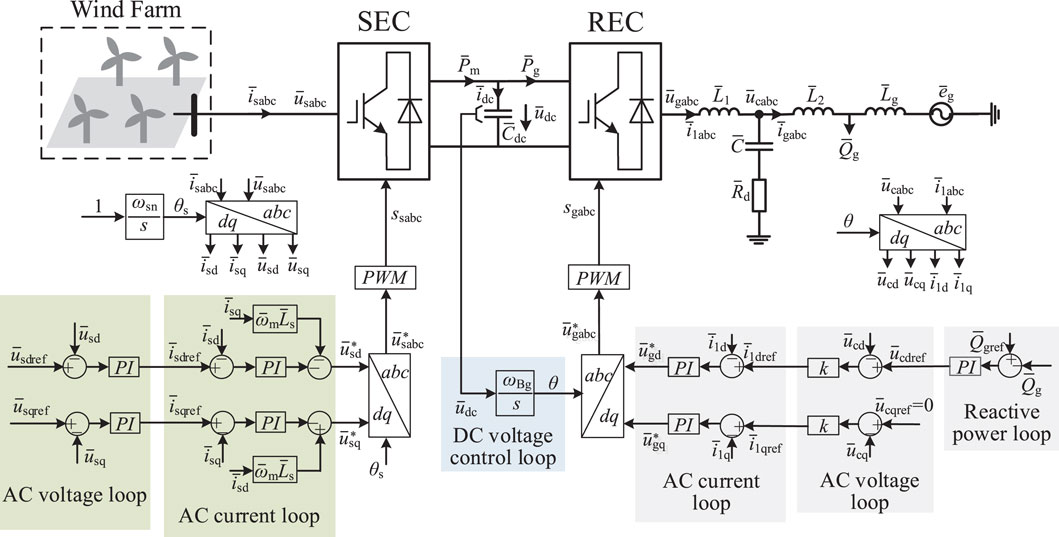
Figure 3. Grid-forming control structure of the VSC-HVDC system.
According to the matching relationship in Figure 2, the DC-side voltage of the REC can be analogized to the SG’s rotor speed. The linkage between the AC-side angular frequency of the REC and the DC voltage is established so that it meets the following conditions:
where
Based on the control principle given by Equation 5, when the active power sent by the SEC to the DC capacitor increases, the DC-side voltage increases. According to the relationship in Equation 5, the AC-side angular frequency
In the outer reactive power control loop of the REC, the difference between the reactive power reference
Different from the ISynC-based GFM control (Wu W. et al., 2019; Li et al., 2022; Ge et al., 2023), the inner current loop is added to the GFM structure in this article, which can limit the output current. The control structure shown in Figure 3 can enable the REC to provide frequency support and realize the grid-forming function.
The SEC takes the AC voltage as the control objective. In the control diagram of the REC, the rated per-unit value of the SEC’s AC frequency, that is, 1 p.u., passes through an integrator whose gain is the rated value of the SEC’s rated angular frequency ωsn, and the output is the phase θs of the SEC’s modulation voltage. In the outer AC voltage control loop of the SEC, the difference between the d-axis reference
Other variable symbols in Figure 3 are explained as follows.
3 Small-signal modeling and stability analysis
In this article, the state-space model-based analysis method is utilized to research the interaction stability between the grid-forming VSC-HVDC system.
3.1 State-space modeling
After linearizing the grid-forming VSC-HVDC system’s control structure, as shown in Figure 3, the small-signal control block diagram shown in Figure 4 can be obtained. For the SEC of the GFM VSC-HVDC system, due to the application of compensation modulation, the SEC’s AC voltage is not relevant to the DC voltage. Thus, the small-signal control diagram of the VSC-HVDC in Figure 4 only covers the REC.

Figure 4. Small-signal control diagram of the VSC-HVDC system under the GFM control.
The state variable Δx is selected in Eq. 6 as
where
Based on the small-signal diagram in Figure 4, the state-space equation of the grid-forming VSC-HVDC system is derived in Eq. 7 as
where H is the state-space matrix of a grid-forming VSC-HVDC system.
The state-space matrix H can be represented in Eqs 8–11 as
where
3.2 Small-signal stability analysis
The characteristic equation of the grid-forming VSC-HVDC system is derived in Eq. 12 as
where λ is the eigenvector, and I is the identity matrix.
The eigenvalues λ1, λ2, ., λn of the GFM VSC-HVDC system can be derived by setting the value of (12) to 0. The quantitative index of small-signal stability margin for the grid-forming VSC-HVDC system is obtained as
where real ( λi) represents the real part of the eigenvalues λi, and |λi| represents the amplitude of the eigenvalues λi.
It can be seen from Equation 13 that the quantitative index ζ represents the system’s characteristics of electrical damping, which can measure the small-signal stability margin. If the value of λ is greater than 0, the GFM VSC-HVDC system can work stably. If the value of λ is negative, the GFM VSC-HVDC system cannot work stably.
Based on parameters in Table 1 and the state-space model, Figure 5 presents the characteristic root locus and minimum damping ratio curves with the change of the short-circuit ratio (SCR) kSCR, where kSCR is equal to the reciprocal of the grid line inductance
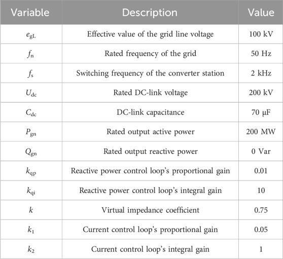
Table 1. Parameters of the grid-forming VSC-HVDC system.
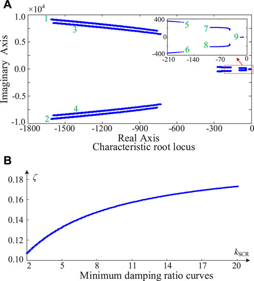
Figure 5. Characteristic root locus and minimum damping ratio curves with the change of SCR. (A) Characteristic root locus. (B) Minimum damping ratio curves.
For the grid-following VSC-HVDC system (Yang et al., 2020), Figure 6 presents the minimum damping ratio curves as the SCR changes, where the REC adopts the conventional vector control, the outer DC voltage loop’s control bandwidth is 20 Hz, the inner current loop’s control bandwidth is 200 Hz, and the PLL’s control bandwidth is 50 Hz. It can be seen from Figure 6 that with the decrease of the SCR from 20 to 2, the minimum damping ratio curves of the grid-following VSC-HVDC gradually decrease below 0, which shows that the grid-following VSC-HVDC can operate stably under the stiff grid condition and will lose stability in a weak grid. Comparing Figures 5, 6 demonstrates that the proposed grid-forming control strategy in this article has better stability than the conventional grid-following VSC-HVDC.
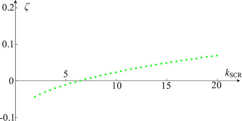
Figure 6. Minimum damping ratio curves of the grid-following VSC-HVDC with the change of SCR.
Figure 7 presents the characteristic root locus and minimum damping ratio curves with the change of the virtual impedance coefficient, where the SCR is 2, the current loop’s proportional gain k1 is 0.05, and the current loop’s integral gain k2 is 1. It can be seen from Figure 7A that when the virtual impedance coefficient k increases from 0 to 5, the nine root trajectories of the system are all distributed in the left half plane, corresponding to the stable operations of the grid-forming VSC-HVDC system. Furthermore, when the virtual impedance coefficient k increases from 0 to 5, the minimum damping ratio of the system first increases and then decreases, but it is always greater than 0. Research results shown in Figure 7 illustrate that the VSC-HVDC system under the proposed grid-forming control is robust and can maintain stable operations with a large range variation of the voltage loop parameters.
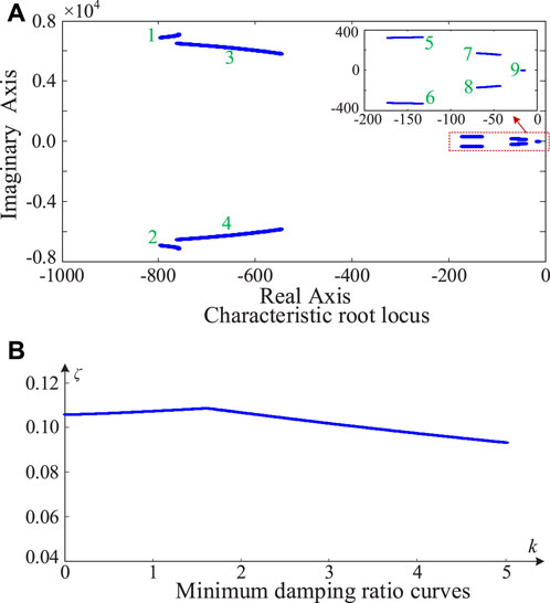
Figure 7. Characteristic root locus and minimum damping ratio curves as the virtual impedance coefficient changes. (A) Characteristic root locus. (B) Minimum damping ratio curves.
Figure 8 presents the characteristic root locus and minimum damping ratio curves as the proportional gain k1 of the current control loop changes, where the SCR is 2, the virtual impedance coefficient k is 0.75, and the current loop’s integral gain k2 is 1. In Figure 8A, when the current loop’s proportional gain k1 increases from 0 to 0.16, the nine root trajectories of the system are all distributed in the left half plane, corresponding to the stable operations of the grid-forming VSC-HVDC system. Moreover, in Figure 8B, when the current control loop’s proportional gain k1 increases from 0 to 0.16, the minimum damping ratio of the system decreases, but it is always greater than 0. Research results in Figure 8 demonstrate that the VSC-HVDC system under the proposed grid-forming control is robust and can maintain stable operations with a large range variation of the current control loop’s proportional gain.
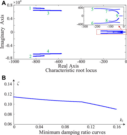
Figure 8. Characteristic root locus and minimum damping ratio curves as the current control loop’s proportional gain changes. (A) Characteristic root locus. (B) Minimum damping ratio curves.
Figure 9 presents the characteristic root locus and minimum damping ratio curves as the current control loop’s integral gain k2 changes, where the SCR is 2, the virtual impedance coefficient k is 0.75, and the current loop’s proportional gain k1 is 0.05.
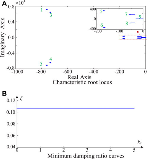
Figure 9. Characteristic root locus and minimum damping ratio curves with the change of the current control loop’s integral gain. (A) Characteristic root locus. (B) Minimum damping ratio curves.
Figure 9A shows that when the current loop’s integral gain k2 increases from 0 to 5, the nine root trajectories of the system are all located in the left half plane and almost remain unchanged, corresponding to the stable operations of the grid-forming VSC-HVDC system. In addition, in Figure 9B, when the current control loop’s integral gain k2 increases from 0 to 5, the minimum damping ratio of the VSC-HVDC almost remains unchanged and is always greater than 0.1. Research results shown in Figure 9 demonstrate that the VSC-HVDC system under the proposed grid-forming control is robust and can maintain stable operations with a large range variation of the current control loop’s integral gain.
4 Mechanism analysis and stabilization control
4.1 Interaction mechanism analysis
This article utilizes the complex power coefficient method (Sang et al., 2019) to reveal the interaction mechanism between the grid-forming VSC-HVDC system and the grid. First, the REC’s grid-connected active power of the VSC-HVDC system can be derived in Eq. 14 by
where
Linearizing the grid-connected active power of the REC in (14) gives
where
According to the linearized output active power in Eq. 15, the vector diagram of the REC’s output active power can be obtained in Figure 10. The synchronous power coefficient Kg of the REC is greater than 0, and the damping power coefficient Dg of the REC is greater than 0. Because the SEC’s output active power is not related to the DC voltage, the variation of the SEC’s output active power
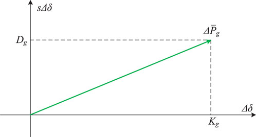
Figure 10. Vector diagram of the REC’s output active power.
It can be seen from Equation 16 that the characteristic equation of the grid-forming VSC-HVDC system is a second-order equation, and the stability of the system is decided by the damping coefficient Dg. Because the value of Dg is greater than 0, the VSC-HVDC system under the proposed grid-forming control is always stable, whether the grid is weak or stiff. The above mechanism analysis results are in accordance with the conclusions of numerical analysis in Section 3, further validating the correctness of the conclusion.
4.2 Stabilization control strategy
Although the minimum damping ratio ζ of the grid-forming VSC-HVDC system is greater than 0, the value of ζ is not big enough; that is, the stability margin is inadequate. Therefore, it is essential to propose a stabilization controller to further improve the system’s small-signal stability. As is well known, a power system stabilizer (PSS) can be added to the excitation system of the SG. The PSS usually takes the rotational speed of the SG as the input signal, and its output is superimposed on the excitation signal to increase the electrical damping. In the proposed GFM control structure of the REC, the modulation voltage amplitude can be analogized to the flux linkage of the SG. Therefore, imitating the stabilization mechanism of the PSS, this section proposes a damping injection strategy according to the DC voltage feedback to change the modulation voltage amplitude of the REC.
Figure 11 presents the control diagram of the stabilization controller and minimum damping ratio curves after adding the stabilization controller. In Figure 11A, a stabilization controller is added to the original grid-forming structure. The input of the stabilization controller is the DC-side capacitor voltage, and the output of the stabilization controller is superimposed on the per-unit d-axis modulation voltage
where s is the Laplace operator, kq is the stabilization controller’s gain, and Tq is the stabilization controller’s time constant.
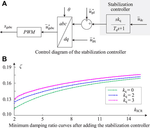
Figure 11. Stabilization controller. (A) Control diagram. (B) Minimum damping ratio curves after adding the stabilization controller.
Figure 11B presents the minimum damping ratio curves of the grid-forming VSC-HVDC system after adding the stabilization controller, where Tq is 0.1. It can be seen that with the increasing of the stabilization gain, kq, from 0 to 2 and 3, the small-signal stability quantitative index ζ is promoted overall. The research result shown in Figure 11B illustrates that the proposed stabilization controller can further enhance the grid-forming VSC-HVDC’s stability, whether under stiff or weak grid conditions.
Figure 11A shows that the parameters needed to be designed are kq and Tq. The high-pass filter in the stabilization controller can pass through signals with a frequency greater than 1/Tq rad/s. When designing the time constant Tq, it is essential to enable the signal of resonant frequency to pass through. Increasing the value of the stabilization controller’s gain kq can improve the stability of the GFM VSC-HVDC. Because increasing the DC-side voltage during the dynamic process will increase the modulation ratio of the REC after adding the stabilization controller, the REC’s modulation ratio m is represented in Eq. 18 as
where
Because the per-unit DC-side voltage can track the per-unit grid frequency, the variation of the DC-side voltage
where mmax is the maximum value of the REC’s modulation ratio.
According to the range of kq and Tq, designing the gain and time constant of the stabilization controller follows the steps below.
Step 1. he potential resonant frequency of the GFM VSC-HVDC system can be derived by building the GFM VSC-HVDC’s state-space model.
Step 2. he time constant Tq of the stabilization controller is tuned based on the derived potential resonant frequency.
Step 3. A value for the stabilization controller’s gain kq is provided and substituted into the state-space model of the GFM VSC-HVDC system.
Step 4. If the electrical oscillation is suppressed and the stability margin is big enough, the design of the stabilization controller is completed. Otherwise, return to step 2 and redesign the parameters.
In contrast, as shown in Figure 11A, a variation related to
where Ds is the system’s damping coefficient provided by the stabilization controller.
According to the control diagram of the stabilization controller in Figure 11A, because the stabilization controller’s time constant is fixed, the variation of the modulation voltage’s amplitude
5 Simulation verification
To further prove the practicability of the presented GFM strategy for the VSC-HVDC system and demonstrate the correctness of stability analysis, simulations have been carried out based on the PSCAD/EMTDC. The electrical and control parameters of the simulation system are shown in Table 1.
Figure 12 presents the simulation results of the VSC-HVDC transmission system as the SCR changes. In Figure 12A, where the VSC-HVDC adopts the presented grid-forming control in this article, and the grid’s short-circuit ratio kSCR decreases from 2.1 to 2.0, the DC-side voltage fluctuates and then returns to a stable state. The VSC-HVDC system’s grid-connected active power fluctuates and then recovers stability. Simulation results in Figure 12A show that the VSC-HVDC under the proposed grid-forming control can work stably in weak grids. In Figure 12B, where the VSC-HVDC utilizes the conventional grid-following control, the bandwidth of the outer DC voltage control loop is 20 Hz, the inner current loop’s control bandwidth is 200 Hz, and the control bandwidth of the PLL is 50 Hz. The DC-side voltage and the grid-connected active power of the VSC-HVDC gradually oscillate and diverge with the grid’s short-circuit ratio kSCR decreasing from 6.5 to 6.4, demonstrating that the stability of the conventional grid-following VSC-HVDC deteriorates when the grid’s stiffness decreases. Simulation results in Figure 12A illustrate that the VSC-HVDC under the proposed GFM control can work stably when the SCR decreases from 2.1 to 2.0, which is in accordance with the numerical analysis conclusions shown in Figure 5. The critically stable value of the SCR in Figure 12B is 6.5, which is approximately equal to the value shown in Figure 6. The simulation results shown in Figure 12B are in accordance with the numerical analysis conclusions in Figure 6. Furthermore, comparing Figure 12B with Figure 12A, the VSC-HVDC under the presented GFM control has better stability than that under the conventional GFL control in weak grids.
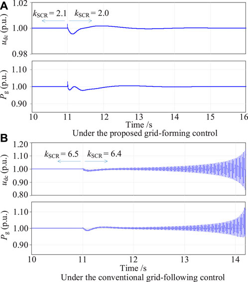
Figure 12. Simulation results of the VSC-HVDC as the SCR changes. (A) Under the proposed grid-forming control. (B) Under the conventional grid-following control.
Figure 13 shows the simulation results of the grid-forming VSC-HVDC as control parameters change. In Figure 13A, where the SCR is 2, the current control loop’s proportional gain k1 is 0.05, the integral gain k2 of the current control loop is 1, and the voltage control loop’s virtual impedance coefficient k changes from 0.75 to 1.2. The DC-side voltage and the grid-connected active power of the GFM VSC-HVDC system fluctuate slightly and then recover. No oscillations occur in the DC-side voltage and the grid-connected active power, demonstrating that the VSC-HVDC under the presented GFM control is robust and can maintain stable operations with a large range variation of the voltage loop parameters. Simulation results in Figure 13A illustrate that the VSC-HVDC under the proposed GFM control can work stably when the virtual impedance coefficient k increases from 0.75 to 1.2, which is in accordance with numerical analysis conclusions in Figure 7. In Figure 13B, where the SCR is 2, the virtual impedance coefficient k is 0.75, the current control loop’s proportional gain k1 changes from 0.05 to 0.1, and the current control loop’s integral gain k2 changes from 1 to 1.5. Small-amplitude oscillations occur in the DC-side voltage and grid-connected active power of the grid-forming VSC-HVDC system, indicating that the VSC-HVDC system under the proposed grid-forming control is robust and can maintain stable operations with a large range variation of the current control loop’s integral gain. Simulation results in Figure 13B illustrate that the VSC-HVDC under the proposed GFM control can work stably when the parameters of the current control loop change, which is in accordance with numerical analysis conclusions in Figure 8.
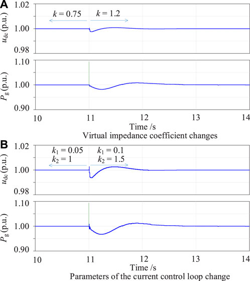
Figure 13. Simulation waveforms of the grid-forming VSC-HVDC as control parameters change. (A) Virtual impedance coefficient changes. (B) Parameters of the current control loop change.
Figure 14 presents simulation waveforms of the grid-forming VSC-HVDC system when providing inertia response, where the SCR is 2, the current control loop’s proportional gain k1 is 0.05, the current control loop’s integral gain k2 is 1, and the virtual impedance coefficient k of the voltage control loop is 0.75. In Figure 14A, when the grid frequency falls from the rated value to 99% of the rated value, the DC voltage of the grid-forming VSC-HVDC can automatically track grid frequency, acting as the PLL. Based on the DC-side voltage in the per-unit form, the source renewable energy (e.g., wind farm) increases the output active power to provide inertia response to the grid. The grid-connected active power Pg of the grid-forming VSC-HVDC increases by 0.24 p.u. and then recovers. In Figure 14B, the DC-side voltage of the grid-forming VSC-HVDC can automatically track the grid frequency as the grid frequency increases from the rated value to 101% of the rated value. According to the DC-side voltage in the per-unit form, the source of the renewable energy (e.g., wind farm) reduces the output active power to provide inertia support to the grid. The output active power Pg of the REC grid-forming VSC-HVDC system decreases by 24% and then recovers. Simulation results in Figure 14 demonstrate that the presented grid-forming control can make the VSC-HVDC automatically sense the grid frequency and realize the function of inertia response.
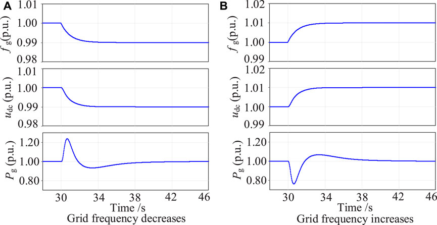
Figure 14. Simulation waveforms of the grid-forming VSC-HVDC system when providing the inertia response. (A) Under the proposed grid-forming control. (B) Under the conventional forming control.
6 Conclusion
A novel grid-forming control strategy with the function of limiting the output current is proposed to deal with the interaction instability issues between a conventional grid-following VSC-HVDC system and the grid. A state-space model of the grid-forming VSC-HVDC system is established to research the small-signal stability, and the eigenvalue analysis method is adopted. Moreover, the complex power coefficient method is utilized to reveal the interaction mechanism between the grid-forming VSC-HVDC system and the grid. To further improve the stability margin of the grid-following VSC-HVDC system, a stabilization controller is proposed for the original grid-forming structure, which can introduce positive electrical damping. Conclusions are obtained as follows:
1) The grid-forming control strategy makes the REC realize the function of self-synchronization with the grid through the dynamics of the DC capacitor. The per-unit DC voltage can automatically track the grid frequency, acting as a phase-locked loop.
2) Different from the conventional grid-following VSC-HVDC, which loses stability in a weak grid, the VSC-HVDC system under the proposed grid-forming control can work stably in both stiff and weak grids.
3) The VSC-HVDC system under the proposed grid-forming control is robust and can maintain stable operations with a large range variation of the parameters in the current and voltage control loop.
Data availability statement
The raw data supporting the conclusions of this article will be made available by the authors, without undue reservation.
Author contributions
YL: formal analysis, writing–original draft, and writing–review and editing. GS: validation, writing–original draft, and writing–review and editing. QC: investigation, resources, and writing–original draft. PQ: software and writing–review and editing. JZ: Investigation, supervision, and writing–review and editing. RY: project administration and writing–review and editing. JZ: funding acquisition and writing–review and editing.
Funding
The author(s) declare financial support was received for the research, authorship, and/or publication of this article. This work is supported by the Science and Technology Project of State Grid Zhejiang Electric Power Co., Ltd (5211DS230005) and partly by the National Natural Science Foundation of China (No. 52107201).
Conflict of interest
Authors YL, QC, and PQ were employed by the Electric Power Research Institute of State Grid Zhejiang Electric Power Corporation.
The remaining authors declare that the research was conducted in the absence of any commercial or financial relationships that could be construed as a potential conflict of interest.
The authors declare that this study received funding from State Grid Zhejiang Electric Power Co., Ltd. The funder had the following involvement in the study: investigation and resources.
Publisher’s note
All claims expressed in this article are solely those of the authors and do not necessarily represent those of their affiliated organizations, or those of the publisher, the editors, and the reviewers. Any product that may be evaluated in this article, or claim that may be made by its manufacturer, is not guaranteed or endorsed by the publisher.
References
Fu, X., Sun, J., Huang, M., Tian, Z., Yan, H., Iu, H. H. C., et al. (2021). Large-signal stability of grid-forming and grid-following controls in voltage source converter: a comparative study. IEEE Trans. Power Electron. 36 (7), 7832–7840. doi:10.1109/tpel.2020.3047480
Ge, P., Tu, C., Xiao, F., Guo, Q., and Gao, J. (2023). Design-oriented analysis and transient stability enhancement control for a virtual synchronous generator. IEEE Trans. Industrial Electron. 70 (3), 2675–2684. doi:10.1109/tie.2022.3172761
Huang, S., Yao, J., Pei, J., Chen, S., Luo, Y., and Chen, Z. (2022). Transient synchronization stability improvement control strategy for grid-connected VSC under symmetrical grid fault. IEEE Trans. Power Electron. 37 (5), 4957–4961. doi:10.1109/tpel.2021.3131361
Li, C., Yang, Y., Cao, Y., Wang, L., and Blaabjerg, F. (2022). Frequency and voltage stability analysis of grid-forming virtual synchronous generator attached to weak grid. IEEE J. Emerg. Sel. Top. Power Electron. 10 (3), 2662–2671. doi:10.1109/jestpe.2020.3041698
Liu, D., Jiang, K., Ji, X., Cao, K., Xu, C., Sang, S., et al. (2024). Improved VSG strategy of grid forming inverters for supporting inertia and damping. Front. Energy Res. 11, 1331024. doi:10.3389/fenrg.2023.1331024
Ma, J., Su, N., and Shen, Y. (2024). Stability analysis for direct-drive wind farm transmitted via flexible DC system based on dynamic energy. CSEE J. Power Energy Syst. doi:10.17775/CSEEJPES.2022.07150
Meng, X., Liu, J., and Liu, Z. (2019). A generalized droop control for grid-supporting inverter based on comparison between traditional droop control and virtual synchronous generator control. IEEE Trans. Power Electron. 34 (6), 5416–5438. doi:10.1109/tpel.2018.2868722
Pan, D., Wang, X., Liu, F., and Shi, R. (2020). Transient stability of VoltageSource converters with grid-forming control: a design-oriented study. IEEE J. Emerg. Sel. Top. Power Electron. 8 (2), 1019–1033. doi:10.1109/jestpe.2019.2946310
Pawar, B., Batzelis, E. I., Chakrabarti, S., and Pal, B. C. (2021). Grid-forming control for solar PV systems with power reserves. IEEE Trans. Sustain. Energy 12 (4), 1947–1959. doi:10.1109/tste.2021.3074066
Sang, S., Gao, N., Cai, X., and Li, R. (2018). A novel power-voltage control strategy for the grid-tied inverter to raise the rated power injection level in a weak grid. IEEE J. Emerg. Sel. Top. Power Electron. 6 (1), 219–232. doi:10.1109/jestpe.2017.2715721
Sang, S., Zhang, C., Cai, X., Molinas, M., Zhang, J., and Rao, F. (2019). Control of a type-IV wind turbine with the capability of robust grid synchronization and inertial response for weak grid stable operation. IEEE Access 7, 58553–58569. doi:10.1109/access.2019.2914334
Shao, B., Zhao, S., Yang, Y., Gao, B., and Blaabjerg, F. (2021). Sub-synchronous oscillation characteristics and analysis of direct-drive wind farms with VSC-HVDC systems. IEEE Trans. Sustain. Energy 12 (2), 1127–1140. doi:10.1109/tste.2020.3035203
Shao, H., Cai, X., Li, Z., Zhou, D., Sun, S., Guo, L., et al. (2019b). Stability enhancement and direct speed control of DFIG inertia emulation control strategy. IEEE Access 7, 120089–120105. doi:10.1109/access.2019.2937180
Shao, H., Cai, X., Zhou, D., Li, Z., Zheng, D., Cao, Y., et al. (2019a). Equivalent modeling and comprehensive evaluation of inertia emulation control strategy for DFIG wind turbine generator. IEEE Access 7, 64798–64811. doi:10.1109/access.2019.2917334
Wang, X., Taul, M. G., Wu, H., Liao, Y., Blaabjerg, F., and Harnefors, L. (2020). Grid-synchronization stability of converter-based resources—an overview. IEEE Open J. Industry Appl. 1, 115–134. doi:10.1109/ojia.2020.3020392
Wang, X., Yao, J., Pei, J., Sun, P., Zhang, H., and Liu, R. (2019). Analysis and damping control of small-signal oscillations for VSC connected to weak AC grid during LVRT. IEEE Trans. Energy Convers. 34 (3), 1667–1676. doi:10.1109/tec.2019.2915680
Wu, Q., Huang, Y., Li, C., Gu, Y., Zhao, H., and Zhan, Y. (2019a). Small signal stability of synchronous motor-generator pair for power system with high penetration of renewable energy. IEEE Access 7, 166964–166974. doi:10.1109/access.2019.2953514
Wu, W., Zhou, L., Chen, Y., Luo, A., Dong, Y., Zhou, X., et al. (2019b). Sequence impedance-based stability comparison between VSGs and traditional grid-connected inverters. IEEE Trans. Power Electron. 34 (1), 46–52. doi:10.1109/tpel.2018.2841371
Yang, R., Shi, G., Cai, X., Zhang, C., Li, G., and Liang, J. (2020). Autonomous synchronizing and frequency response control of multi-terminal DC systems with wind farm integration. IEEE Trans. Sustain. Energy 11 (4), 2504–2514. doi:10.1109/tste.2020.2964145
Yang, R., Zhang, C., Cai, X., and Shi, G. (2018). Autonomous grid-synchronising control of VSC-HVDC with real-time frequency mirroring capability for wind farm integration. IET Renew. Power Gener. 12 (13), 1572–1580. doi:10.1049/iet-rpg.2017.0824
Zha, Y., Lin, J., Li, G., Wang, Y., and Zhang, Yi (2021). Analysis of inertia characteristics of photovoltaic power generation system based on generalized droop control. IEEE Access 9, 37834–37839. doi:10.1109/access.2021.3059678
Zhang, H., Xiang, W., Lin, W., and Wen, J. (2021). Grid forming converters in renewable energy sources dominated power grid: control strategy, stability, application, and challenges. J. Mod. Power Syst. Clean Energy 9 (6), 1239–1256. doi:10.35833/mpce.2021.000257
Zhang, N., Jia, H., Hou, Q., Zhang, Z., Xia, T., Cai, X., et al. (2023). Data-driven security and stability rule in high renewable penetrated power system operation. Proc. IEEE 111 (7), 788–805. doi:10.1109/jproc.2022.3192719
Keywords: grid-forming control, VSC-HVDC, state-space modeling, interaction stability, weak grid, stabilization control
Citation: Lu Y, Shi G, Chen Q, Qiu P, Zhou J, Yang R and Zhang J (2024) Stability analysis and stabilization control of a grid-forming VSC-HVDC system. Front. Energy Res. 12:1437287. doi: 10.3389/fenrg.2024.1437287
Received: 23 May 2024; Accepted: 19 July 2024;
Published: 07 August 2024.
Edited by:
Yonghui Liu, Hong Kong Polytechnic University, Hong Kong SAR, ChinaReviewed by:
Yuqing Dong, The University of Tennessee, United StatesZhenxiong Wang, Xi’an Jiaotong University, China
Huangqing Xiao, South China University of Technology, China
Copyright © 2024 Lu, Shi, Chen, Qiu, Zhou, Yang and Zhang. This is an open-access article distributed under the terms of the Creative Commons Attribution License (CC BY). The use, distribution or reproduction in other forums is permitted, provided the original author(s) and the copyright owner(s) are credited and that the original publication in this journal is cited, in accordance with accepted academic practice. No use, distribution or reproduction is permitted which does not comply with these terms.
*Correspondence: Gang Shi, cGVyZXNlYXJjaGVyQHllYWgubmV0