 Chunyu Yin
 Zhong Xiao1*
 Changbing Tang
 Shichao Liu
- 1Science and Technology on Reactor System Design Technology Laboratory, Nuclear Power Institute of China, Chengdu, China
- 2Faculty of Architecture, Civil and Transportation Engineering, Beijing University of Technology, Beijing, China
Fully ceramic microencapsulated (FCM) fuel is a five-layer intercalation system material consisting of a UO2 core, a sparse pyrolytic carbon layer (Buffer), an inner dense pyrolytic carbon layer (IPyC), an outer dense pyrolytic carbon layer (OPyC), and a silicon carbide matrix (SiC). At first, this paper researched the thermodynamic models of the materials, including heat conduction coefficient, Young’s modulus, thermal expansion coefficient, etc. Then DIGIMAT, the finite element software, was used to establish the equivalent volume element (RVE) for the equivalent analysis of the thermodynamic properties of the FCM fuel pellet. Finally, the thermodynamic equivalent performance model of FCM fuel was obtained by multi-factor fitting analysis. The results show that among these thermodynamic properties of FCM fuel pellets, the Young’s modulus, thermal expansion coefficient and plastic performance are mainly affected by temperature, fast neutron fluence, and UO2 volume fraction; the specific heat capacity is mainly affected by UO2 volume fraction and temperature; the heat conduction coefficient is mainly affected by temperature and UO2 volume fraction. The thermal conductivity is mainly affected by temperature, burnup and UO2 volume fraction. In this study, the equivalent models obtained through the fitting analysis of RVE model parameters can well describe the thermodynamic behavior of FCM fuel particles.
1 Introduction
After the Fukushima nuclear accident, the need to improve the reliability of fuel performance under accident conditions has been underscored, resulting in Accident Tolerant Fuel (ATF) becoming a prominent research topic. Fully Ceramic Microencapsulated (FCM) fuel has been proposed as a primary research direction due to its superior fission products containment, thermomechanical properties and corrosion resistance in high-temperature and high-radiation environments. These characteristics are acknowledged for their capacity to significantly reduce the risk of fuel failure during accidents. Consequently, FCM fuel has been identified as having considerable potential to enhance the safety and operational reliability of nuclear reactors (Chun et al., 2015; Zhang et al., 2021a; Yeon Choi et al., 2021; Li et al., 2022).
In FCM, the tri-structural isotropic (TRISO) fuel particles are dispersed in SiC matrix, which has the characteristics of good oxidation resistance, high thermal conductivity, high chemical stability, strong fission product tolerance, strong radiation resistance and corrosion resistance (Brown et al., 2013; Xiang et al., 2014; Cao et al., 2018; Lu et al., 2018; Li Zhuocheng et al., 2019; Zhang et al., 2021a; Zhang et al., 2021b; Liu et al., 2022). The TRISO consists of a spherical fuel core coated with a porous carbon buffer (Buffer) layer, an inner pyrolytic carbon (IPyC) layer, a chemical vapor deposition silicon carbide (SiC) layer and an outer pyrolytic carbon (OPyC) layer (Skerjanc et al., 2016; Schappel et al., 2018; Tyler et al., 2020; Wei et al., 2021).
The FCM has significant security benefits, but it also has certain disadvantages. The TRISO and SiC matrix replaces 95% of the volume of traditional UO2 fuel, which results in a reduced fuel rod cycle length (Terrani et al., 2020). The elasticity, creep and shrinkage deformation of PyC layer are highly anisotropic (Hongyang et al., 2021). The non-uniform temperature distribution leads to different thermal expansion strains of each layer (Hartanto et al., 2015). The accumulation of solid and gaseous fission products results in the irradiation-induced swelling of TRISO fuel particles (Hongyang et al., 2019). Buffer layer and PyC layer will be deformed by irradiation shrinkage (Hongyang et al., 2019). Irradiation also reduces thermal conductivity of SiC (Cao et al., 2018; Zhou and Zhou, 2018). Assessing thermodynamic performance is vital as it directly influences the fuel’s ability to endure the high temperatures and radiation levels encountered during reactor operations. The thermodynamic parameters are key to identifying potential failure modes, optimizing fuel design, and ensuring long-term stability and performance. By gaining a thorough understanding of the thermodynamic behavior of FCM fuel, researchers can master its accident tolerance, ultimately contributing to the improvement of the safety and efficiency of nuclear reactors. Therefore, it is necessary to calculate and evaluate the thermodynamic performance of FCM to ensure its safety and reliability in pile.
2 Review on simulation on thermodynamic properties of FCM
FCM is a new type of ATF fuel, and accurate fuel and material performance model is the prerequisite to ensure accurate fuel performance analysis. So far, many researchers have used various simulation tools and methods to simulate the thermodynamic properties of FCM.
Hongyang et al. (2021) studied the effects of initial porosity and creep coefficient of porous buffer layer on the thermo-mechanical coupling behavior of FCM particles by inert matrix fuel thermodynamic analysis (TMAIMF) code. Li R. et al. (2019) evaluated the stress effects of fuel particles under normal or extreme conditions by the Monte Carlo method. Tang et al. (2019) simulated the irradiation-thermal-mechanical coupling behavior of FCM by ABAQUS encoded UMAT subroutine. Wei et al. (2019) studied the influence of TRISO parameters and core parameters on the effective thermal effect of porous carbon by finite element (FE). Kamalpour et al. (2018) analyzed the temperatures of the fuel, cladding, and coolant under normal operating conditions by COMSOL and RELAP5. Zhang et al. (2021a) studied the thermodynamic properties of FCM by establishing a finite element analysis (FEM) model. Schappel et al. (2018) established a fuel performance model of FCM by using BISON code and simulated the thermodynamic behavior of FCM in LWR. Zhang et al. (2021b) established a finite element method (FEM) model based on cohesive region model (CZM) for the analysis of TRISO-matrix debonding properties. Mihaila et al. (2012) studied the thermodynamic performance of fuel rods by finite element simulation, and accurately predicted the central temperature and radial deformation degree of fuel particles. Wei et al. (2021) established a fuel performance code for thermodynamic analysis of inert matrix Fuel (TMAIMF) based on ABAQUS software to analyze thermal-mechanical coupling and multi-scale behavior in FCM particles. Li R. et al. (2019) studied the change of SiC stress in TRISO coated particles and its sensitivity to size and material properties in the early and late irradiation period by using the analytical solution method. Besmann et al. (2014) used COMSOL to calculate the radial and tangential stress inside TRISO. Blaise (2014) studied the performance of TRISO fuel by PARFUME (Particle Fuel Model) codes. Yeon Choi et al. (2021) used DeCART2D code18 to calculate FCM performance, analyze reactivity coefficient, used MOC (characteristic method) to solve multiple neutron transport equations and evaluate the maximum temperature of fuel and cladding. Wu et al. (2021) used Monte Carlo (MC) method to implement explicit modeling and calculate the transmission and burnup of TRISO. Wu et al. (2020) evaluated the Thermal hydraulic safety by improved subchannel and system analysis code. Hongyang et al. (2019) established an analytical model by combining theoretical analysis with finite element (FE) simulation, and studied the effects of temperature, fission rate, core material, initial porosity, external hydrostatic pressure and creep coefficient of dense PyC based on mesoscopic mechanics method and homogenization theory. Kusuma Dewi et al. (2019) established Maxwell-Eucken and Hasselman-Johnson models to estimate the thermal conductivity of fuel, and further modified it by using the Knudsen effect. Cao et al. (2018) established a Maxwell-Eucken model to predict the effective thermal conductivity of TRISO, and studied the parameters affecting the densification of SiC matrix.
Although many researchers have proposed methods to calculate the thermodynamic performance of FCM, accurate results were rarely obtained, as FCM has the characteristics of high packing fraction (PF) and multi type particle design, requiring many assumptions (Wu et al., 2021). At the same time, it is difficult to model FCM in numerical simulation. And even if it can be achieved, the computational workload is huge, making it difficult to carry out corresponding simulations. This article proposes a new research method based on the finite element software DIGIMAT to establish an equivalent performance RVE model for FCM, in order to further supplement its thermodynamic performance research.
The materials in FCM (Figure 1) include UO2, Buffer, PyC, and SiC, each of which has a complex thermodynamic behavior. The thermodynamic properties of these materials mainly include thermal conductivity, specific heat, density, Young’s modulus, Poisson’s ratio, thermal expansion coefficient, creep deformation, and plastic deformation. Since this study involves numerous properties, it is too clumsy to describe related models one by one. The relevant models of these materials have been extensively studied at home and abroad, and the models selected in this study are mainly from references (Reymann, 1978; Snead et al., 2007; H.-j. lee B.-Wirth, 2008; Miller et al., 2009; Yan, 2009; Jeffrey and Wirth, 2010; Tang et al., 2017a; Koyanagi and Katoh, 2018; Li et al., 2018). The fuel behavior in coated fuel particles can be described based upon kernel migration (Li et al., 2018). Especially, Snead et al. (2007) provided such a handbook of SiC properties for fuel performance modelling, which includes fabrication of silicon carbide, crystal structure, thermal properties, electrical properties, mechanical properties, et al. Also the effects of irradiation on SiC was discussed.
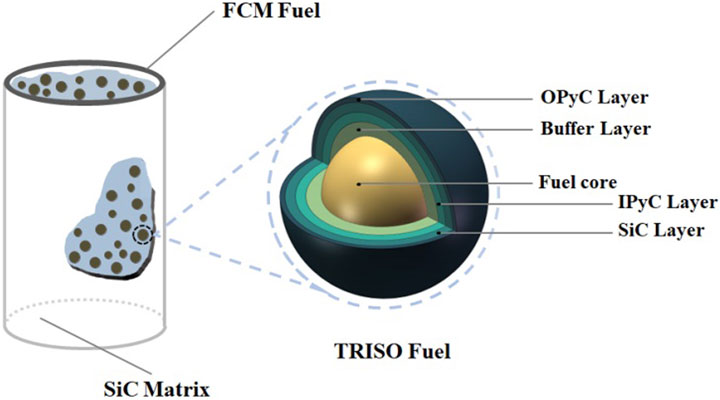
Figure 1. Schematic diagram of FCM pellet.
3 The model solving method based on DIGIMAT
The popular homogenization theories includes analytical methods (mean field theory) and numerical methods (finite element homogenization theory). The first is a homogenization method based on more rigorous mathematical analysis, which is widely used in dealing with the problem of the uniformity of non-periodic materials. The second is very convenient for studying materials with microscopic or microscopic periodic structures, but difficult for studying materials with aperiodic structures (Oleinik et al., 1992). The second method is adopted in this study for uniformly distributed FCM, which belongs to periodic structural materials. The various parameters of the equivalent volume element (RVE) of FCM were simulated by DIGIMAT based on the Mori-Tanaka model.
At the same time, in order to simplify the calculation, the internal phases of SiC materials are constructed with circular or elliptical models, and the FCM fuel properties in the paper default to spatially uniform distribution of TRISO particles in the SiC matrix. In the finite element analysis, the equivalent stress and strain response of the material is obtained by applying the displacement load with the method of cyclic boundary, and the relevant mechanical parameters of the equivalent medium RVE are obtained finally. The mechanical load parameter setting is as follows (Figure 2): the mechanical load setting process: select the type of boundary conditionsperiodic (Periodic) - load type selected free stress (FREE STRESS) - generate (Create).
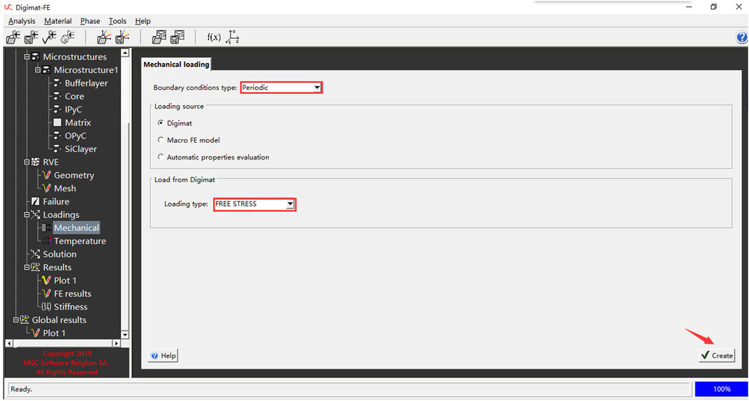
Figure 2. Mechanical load parameter setting diagram.
The main parameters and commonly used units in this formula are shown in Table 1 unless otherwise specified.
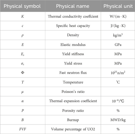
Table 1. Physical quantities and units.
3.1 Methods for solving specific heat and density
The specific heat and density are typical volumetric average physical quantities, and their calculation methods can be weighted based on the volume fractions of different materials. When considering the changes in material density caused by different neutron fluences, the data discretization method is used to discretize the temperature and neutron fluence.
The density is expressed according to the law of conservation of mass as shown in Equation 1:
where, Φ is the neutron flux. In the calculation, Φ is related to time, and the relationship between the density and the various materials at different stages can be obtained.
For specific heat, the following expression can be obtained according to the law of energy conservation, the definition formula of specific heat, and the density equivalent average calculation method as shown in Equation 2:
The results can be obtained by solving in the DIGIMAT-MF module with the above method (Jeffrey and Wirth, 2010).
3.2 Homogenization method for solving thermal conductivity
The thermal conductivity of FCM is related to burnup and temperature. Based on the finite element method, the thermal conductivity of FCM with the i-th particle is estimated as shown in Equation 3.
where,
Once the thermal conductivity coefficients of each layer are obtained through empirical formulas, the finite element method (FEM) can be utilized to derive the equivalent heat flux expressions for the Representative Volume Element (RVE) at different temperatures Then the relevant properties of composite materials can be solved according to the homogenization theory (Zhang et al., 2010; Tang et al., 2017a; Koyanagi and Katoh, 2018).
3.3 Simulation of FCM mechanical parameters based on homogenization theory
When using the homogenization theory based on DIGIMAT to solve parameters related to material mechanics such as Young’s modulus and Poisson’s ratio, the main focus is to calculate the analytical relationship between different material volume contents and mechanical parameters on the macroscopic properties of the mixed equivalent medium. The equivalent volume and shear modulus can be expressed as shown in Equations 4, 5.
where,
The specific method is to use the self consistent method for the first equivalence of multi-layer structures, and then solve it. It is generally called the generalized self-consistent method, and its volume modulus formula is as shown in Equation 6:
Through the above equivalent homogenization methods, the elastic modulus and Poisson’s ratio of the homogenized equivalent medium can be obtained by inputting different particle volume content and material parameters in the DIGIMAT software.
3.4 Thermal expansion coefficient
When simulating the equivalent thermal expansion coefficient of FCM materials, the common characteristic is that the strain will change with temperature. When solving the thermal expansion coefficient of FCM based on DIGIMAT, we can establish the relationship between time step and temperature, and the strain-temperature curve of the equivalent medium material by using a heating process (as shown in Figure 3). In the calculation, we divided the heating process of 1000°C into 100 equidistant incremental steps, and the following formula (Equation 7) can be used and the tangent line can be taken as the thermal expansion coefficient under this temperature condition:
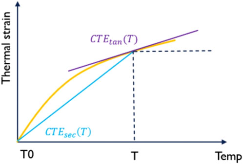
Figure 3. Calculation methods of different thermal expansion coefficients under nonlinear conditions.
To calculate the thermal expansion coefficient, the following steps are performed, leveraging the nonlinear analysis capabilities of DIGIMAT-FE (Snead et al., 2007; H.-j. lee B.-Wirth, 2008; Yan, 2009; Zhang et al., 2010; Terrani et al., 2015; Tang et al., 2017b):
(1) Define the dependence of temperature on E;
(2) Define the dependence of secant CTE on temperature;
(3) Temperature loading is defined from the reference temperature to the maximum temperature;
(4) Thermal deformation is obtained in RVE;
(5) Calculation of effective thermal strain;
(6) The secant CTE is calculated at different temperatures.
3.5 Plastic parameter simulation
The nonlinear deformation and plastic deformation caused by neutron flux and temperature are simulated by the plastic theory. The theoretical formula of plasticity is as shown in Equations 8, 9:
The stress in the above equation is a function of strain, while the elastic parameter of the material changes with the neutron flux and temperature. When the material stress reaches the plastic strength, it enters the inelastic plastic deformation stage.
The incremental expression of plastic deformation is as shown in Equation 10:
According to the above formula, the nonlinear plastic strain caused by temperature and neutron flux can be obtained. The plastic strain can be expressed as shown in Equation 11:
After the tangential stiffness of this increment is determined, the plastic deformation characteristics of FCM materials can be solved by homogenization theory.
4 Equivalent fitting analysis of model calculations
In this work, DIGIMAT was used to create an equivalent volume unit RVE model to characterize the multilayer system of FCM, and the polynomial fitting method was used to fit the equivalent properties of the material, and the fitting process is referred to the equivalent fitting of the Young’s modulus.
In the analysis, the diameter of UO2 core is 425 μm, the thickness of SiC layer is 35 μm, the thickness of IPyC layer and OPyC layer is 40 μm, the thickness of Buffer layer is 100 μm, and the total diameter of a single fuel particle is 855 μm (Tang, 2007). In order to study the effect of UO2 core volume fraction (FVF) on fuel performance, the volume percentage of UO2 core was 10%, 30%, and 50%, respectively. In the analysis, the application range of temperature is 300°C–1,300°C, the application range of burnup is 0–250 MWd/kgU, and the application range of fast neutron flux is 0–1.0 × 1025 n/m2.
4.1 Equivalent Young’s modulus
The Young’s modulus is mainly affected by temperature T, fast neutron flux Ф and volume percentage of UO2 FVF. According to the multifactor polynomial fitting method, we firstly fitted the curves of the relationship between E and T (as shown in Figure 4) at different volume fractions (FVF = 10%, 30%, 50%) and at Ф = 0. Then, the relationship curve between E and Ф,
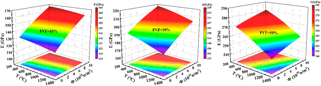
Figure 4. Schematic diagram of the variation trend of Young’s modulus (E) with volume percentage (FVF), temperature (T) and neutron flux (Φ).
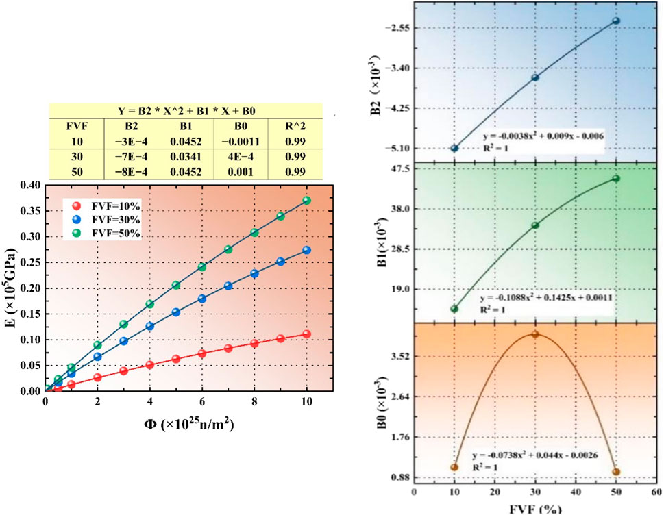
Figure 5. Fitting process of Young’s modulus (E), volume percentage (FVF) and neutron flux (Φ).
Similarly, Figure 6 shows the fitting process of Young’s modulus and T. Finally, we fit the polynomial coefficients of
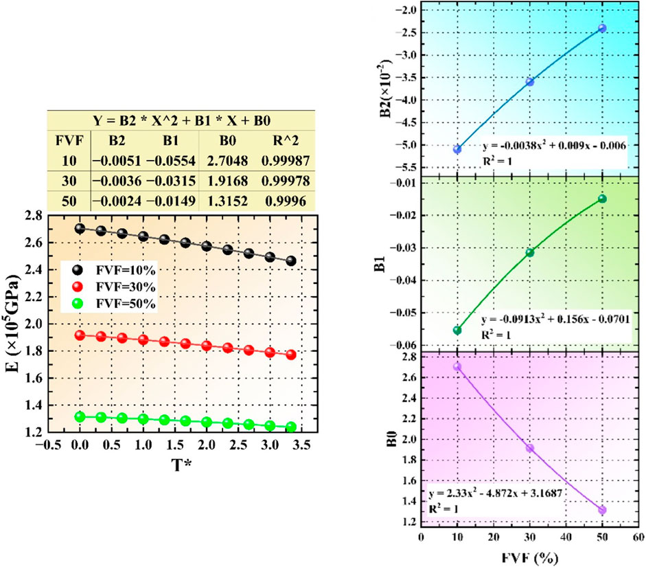
Figure 6. The fitting process of Young’s modulus (E), volume percentage (FVF) and temperature (T).
As illustrated in Figure 5, the Young’s modulus E increases progressively with the increase in fast neutron flux Ф for a given volume fraction FVF. Moreover, higher volume fractions FVF correspond to higher Young’s modulus E. Conversely, Figure 6 shows that for the same volume fraction FVF, the Young’s modulus E decrease with rising temperatures T and in this scenario, larger volume fractions FVF result in a decrease in Young’s modulus E.
4.2 Equivalent density
The density of FCM is only related to the volume percentage and density of each layer of material. Therefore, the analytical solution model can be obtained directly as shown in Equation 13:
4.3 Equivalent specific heat capacity
The specific heat capacity is only related to volume percentage FVF and temperature T. In this study, a three-dimensional bar chart was drawn by means of analytical solution. As shown in Figure 7A, the specific heat capacity of FCM increases with the increase of temperature and decreases with the increase of UO2 volume percentage.
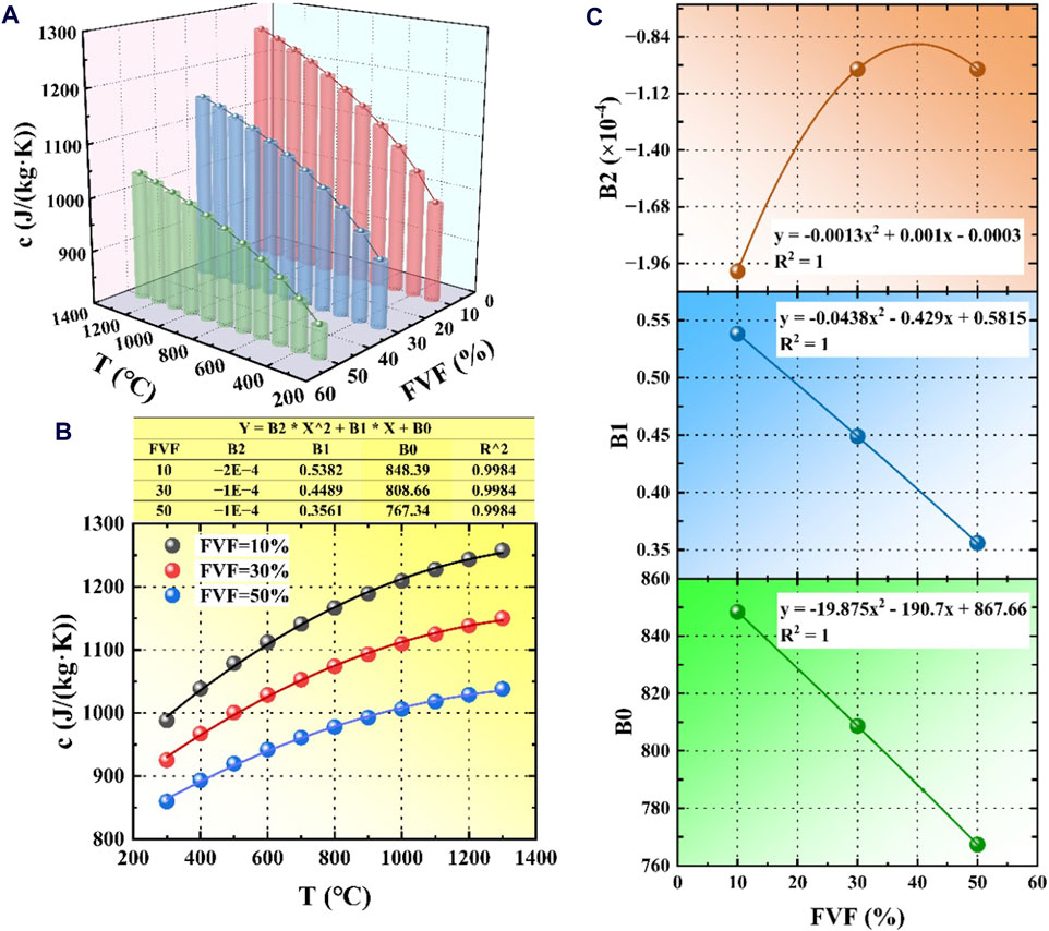
Figure 7. Fitting process of specific heat capacity with volume percentage and temperature. (A) Three-dimensional bar chart of the FCM specific heat capacity; (B) The fitting process of quadratic polynomial; (C) The quadratic polynomial coefficients fitted with the volume percentage FVF.
A quadratic polynomial was used to fit the calculation results, and the fitting process was shown in Figure 7B. In Figure 7B, the equivalent specific heat capacity and temperature T were fitted under different volume percentage, and the quadratic polynomial coefficients fitted in Figure 7C were fitted with the volume percentage FVF respectively, and the calculation model of the specific heat capacity of FCM particles was finally obtained as shown in Equation 14:
4.4 Equivalent thermal conductivity
The thermal conductivity K is mainly related to temperature T, burnup B and volume percentage of UO2 FVF. As shown in Figure 8, the thermal conductivity is negatively correlated with T, B and FVF, in which FVF has the greatest influence on the thermal conductivity, while temperature and burnup have little influence. Only in the range of 300°C–600°C, the thermal conductivity changes significantly with temperature.
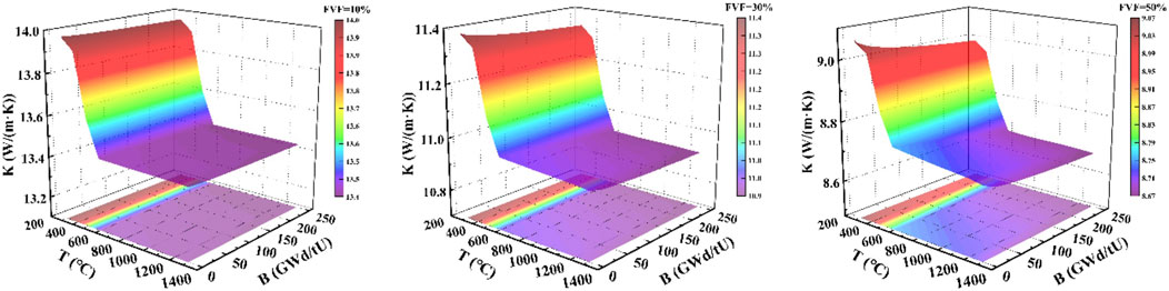
Figure 8. Trend diagram of thermal conductivity (K) with volume fraction (FVF), temperature (T), and burnup (B).
In this paper, a fitting method similar to the equivalent Young’s modulus is used to fit the equivalent thermal conductivity with temperature T, burnup B and UO2 volume percentage FVF in cubic polynomial, as shown in Figure 9. Finally, the thermal conductivity calculation model of FCM is obtained as shown in Equation 15:

Figure 9. The fitting process diagram of heat conduction to temperature and burnup.
4.5 Equivalent thermal expansion coefficient
The thermal expansion coefficient α is similar to the Young’s modulus, which is mainly affected by temperature T, fast neutron flux and volume percentage of UO2 FVF. Figure 10 shows the calculation results of the dense state without considering inter-layer debonding of fuel and the gap state considering inter-layer debonding. It is found that the effect of interlayer state on the thermal expansion coefficient is small.
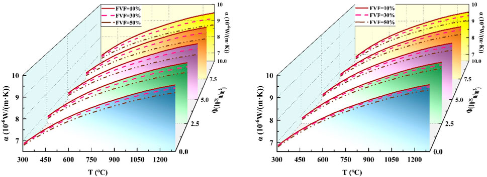
Figure 10. Trend diagram of thermal expansion coefficient (α) with volume percentage (FVF), temperature (T), neutron flux (Φ) (left picture is dense, right picture is gap).
Among the factors affecting the thermal expansion coefficient of FCM, the temperature T has a more obvious effect on it, with a positive correlation trend. However, the fast neutron flux Ф and the volume percentage of UO2 FVF have little influence on it, showing a negative correlation trend.
As shown in Figure 11, a fitting method similar to the Young’s modulus was used to fit the calculated results in the dense state without considering the inter-layer debonding of fuel. Figure 11A shows the fitting process of the thermal expansion coefficient to the temperature, and Figure 11B shows the fitting process of the thermal expansion coefficient to the neutron flux, and finally, the model for calculating the thermal expansion coefficient of FCM in dense state is obtained as shown in Equation 16:
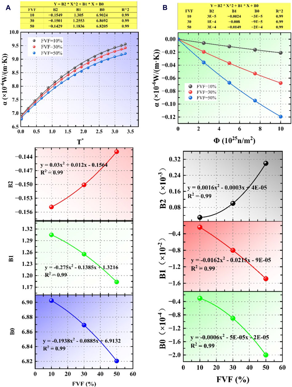
Figure 11. The fitting process diagram of the thermal expansion coefficient (α) to the volume fraction (FVF), temperature (T) and neutron fluence (Φ) under dense conditions. (A) The fitting process of the thermal expansion coefficient to the temperature; (B) The fitting process of the thermal expansion coefficient to the neutron flux.
Similarly, by fitting the calculation results under the gap state considering the inter-layer debonding of fuel, as shown in Figure 12, the calculation model of thermal expansion coefficient of FCM under the gap state can be obtained as shown in Equation 17:
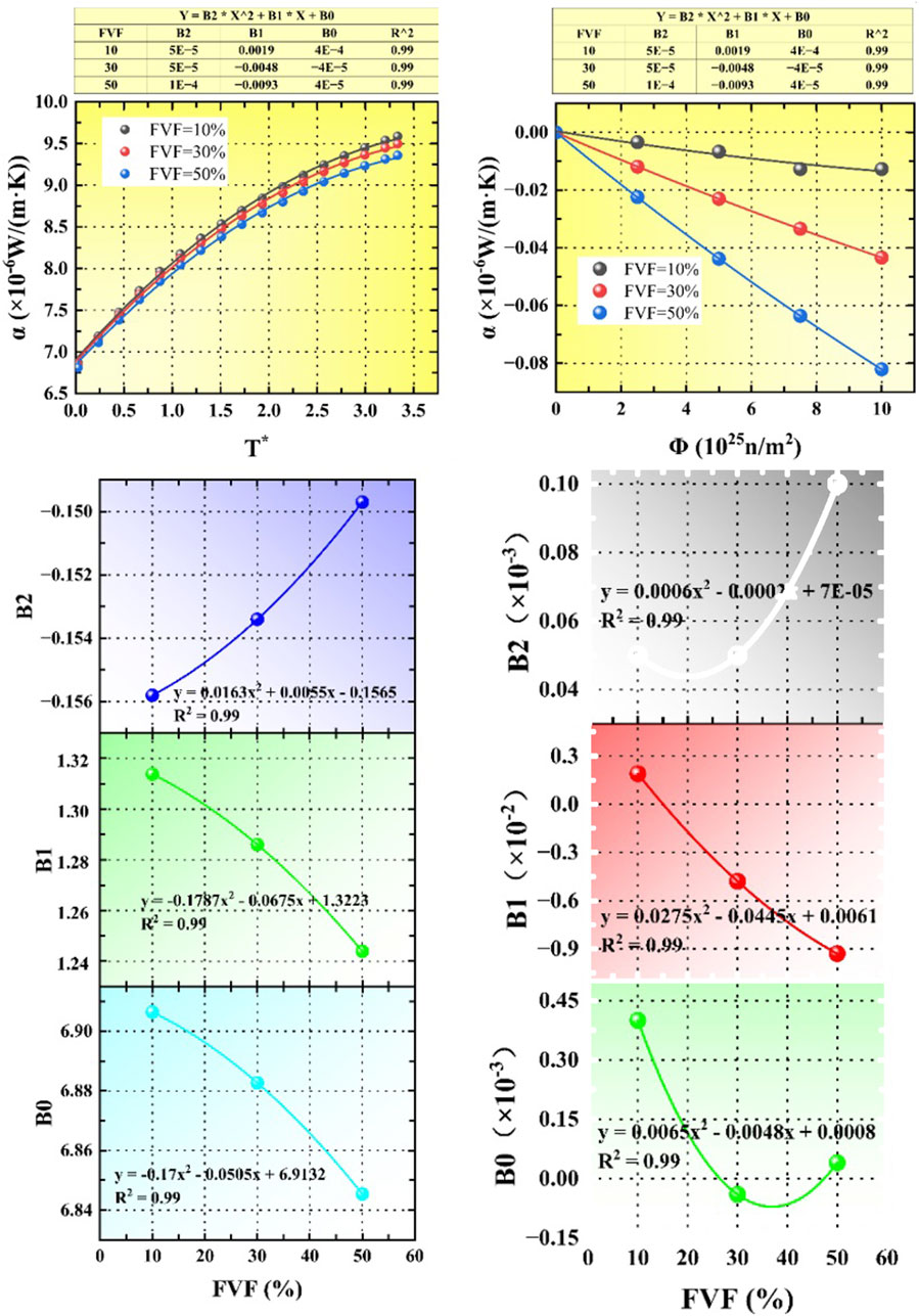
Figure 12. The fitting process diagram of the thermal expansion coefficient (α) with volume fraction (FVF), temperature (T) and neutron fluence (Φ) at gap.
4.6 Equivalent plasticity
In this study, the plastic behavior of FCM particles was characterized with the yield stress and the yield stiffness. The plastic behavior of FCM is mainly affected by temperature T, neutron flux and volume percentage of UO2 FVF. Figure 13 and Figure 14 are the results of the calculation of the yield stiffness and yield stress of the RVE model, respectively, and it can be found that the yield stress and yield stiffness are negatively correlated with temperature, neutron flux rate and volume percentage of UO2, the higher the temperature the smaller the plastic stress within a certain range.
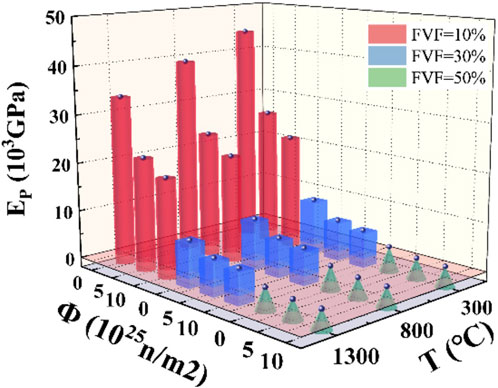
Figure 13. The variation trend of yield stiffness with volume percentage (FVF), temperature (T) and neutron flux (Φ).
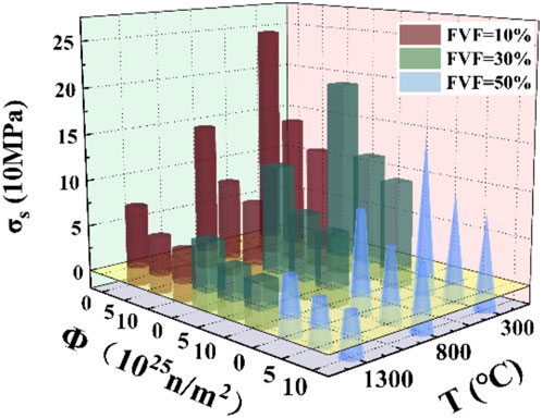
Figure 14. The variation trend of yield stress with volume percentage (FVF), temperature (T), neutron flux (Φ).
The calculation results of the yield stiffness and the yield stress of the RVE model were fitted using a similar fitting method to the Young’s modulus, and the fitting process is shown in Figure 15 and Figure 16.
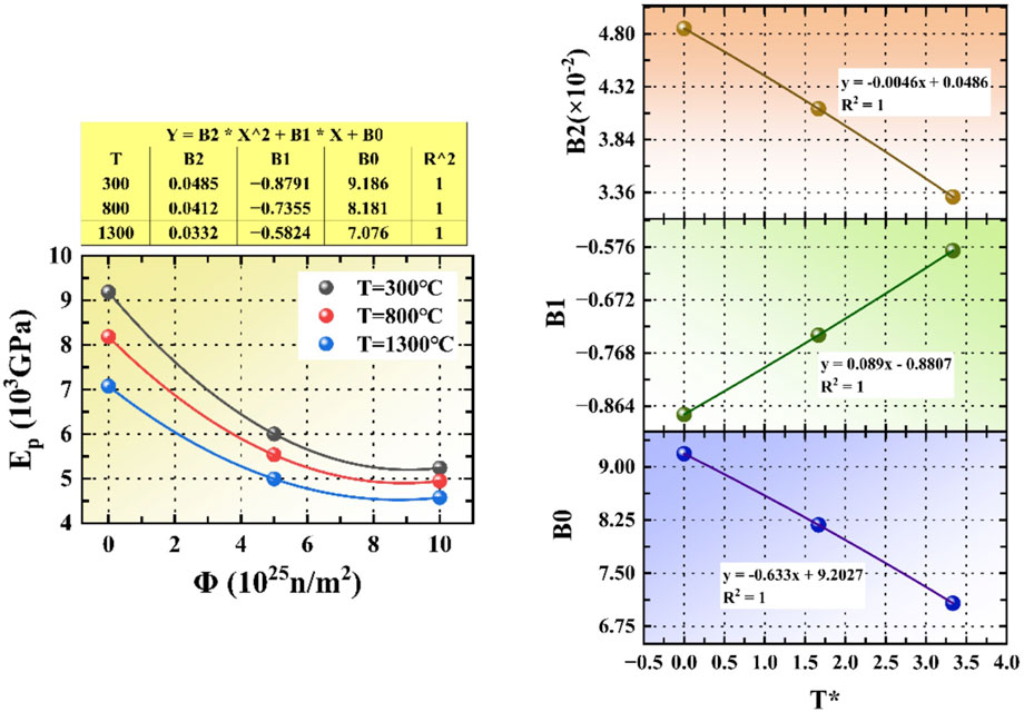
Figure 15. The fitting process diagram of yield stiffness with volume percentage (FVF), temperature (T) and neutron flux (Φ).
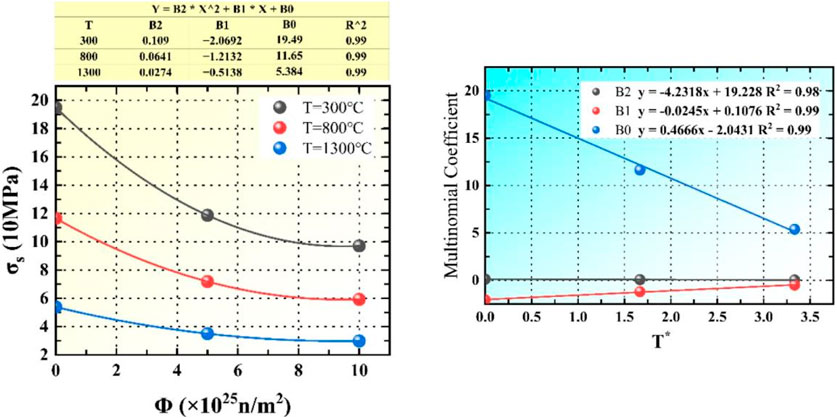
Figure 16. The fitting process diagram of yield stress with volume percentage (FVF), temperature (T) and neutron flux (Φ).
In this study, the plastic deformation at different temperatures and different neutron fluxes was fitted and analyzed when the volume percentage FVF was 30%, and the yield stress calculation model was obtained as shown in Equations 18, 19:
The calculation model of yield stiffness is as follows:
where, the
5 Conclusion
In this study, the RVE model of FCM was established by the finite element analysis software DIGIMAT. Based on the investigation of the properties of various materials, this article carries out the analysis and prediction of the thermodynamic equivalent performance of FCM, which can well describe the change rule of the performance parameters of the RVE model with the influencing factors, and the following conclusions were obtained.
(1) Among the thermodynamic performance parameters of FCM, the plastic deformation is mainly affected by temperature and neutron flux, and within a certain range, the higher the temperature, the smaller the plastic stress.
(2) The specific heat capacity of the FCM is mainly affected by the volume percentage of UO2 and temperature, and the specific heat capacity decreases with the increase of volume percentage and increases with the increase of temperature.
(3) Due to the interlayer separation caused by volume change in the process of the thermal expansion of the FCM, the changes of the two stages of compaction and gap should be considered in the study, and the thermal expansion coefficient is mainly affected by temperature, neutron flux and UO2 volume percentage. In the dense stage, the thermal expansion coefficient decreases with the increase of volume percentage of UO2 and neutron flux, and increases with the increase of temperature. While in the interstitial stage, the thermal expansion coefficient decreases with the influence of neutron flux and temperature, but decreases due to the influence of volume fraction.
(4) The thermal conductivity of FCM is greatly affected by temperature and UO2 volume percentage, as well as by burnup. The thermal conductivity decreases steadily with the increase of temperature, volume percentage and burnup.
(5) The elastic modulus of FCM is mainly affected by temperature, neutron flux, and UO2 volume percentage. The Young’s modulus decreases with the increase of temperature and increases with the increase of neutron flux and UO2 volume percentage.
Data availability statement
The original contributions presented in the study are included in the article/supplementary material, further inquiries can be directed to the corresponding authors.
Author contributions
CY: Conceptualization, Formal Analysis, Investigation, Writing–original draft. ZX: Resources, Validation, Writing–review and editing. KZ: Resources, Supervision, Writing–review and editing. PC: Investigation, Methodology, Validation, Writing–review and editing. CT: Formal Analysis, Validation, Writing–review and editing. LH: Writing–review and editing, Investigation, Validation. SL: Writing–review and editing, Software, Validation.
Funding
The author(s) declare that no financial support was received for the research, authorship, and/or publication of this article.
Conflict of interest
The authors declare that the research was conducted in the absence of any commercial or financial relationships that could be construed as a potential conflict of interest.
Publisher’s note
All claims expressed in this article are solely those of the authors and do not necessarily represent those of their affiliated organizations, or those of the publisher, the editors and the reviewers. Any product that may be evaluated in this article, or claim that may be made by its manufacturer, is not guaranteed or endorsed by the publisher.
References
Besmann, T. M., Ferber, M. K., Lin, H.-T., and Collin, B. (2014). Fission product release and survivability of UN-kernel LWR TRISO fuel. J. Nucl. Mater. 448 (1), 412–419. doi:10.1016/j.jnucmat.2013.10.034
Blaise, P. C. (2014). Modeling and analysis of UN TRISO fuel for LWR application using the PARFUME code. J. Nucl. Mater. 451 (1), 65–77. doi:10.1016/j.jnucmat.2014.03.032
Brown, N. R., Ludewig, H., Aronson, A., Raitses, G., and Todosow, M. (2013). Neutronic evaluation of a PWR with fully ceramic microencapsulated fuel. Part I: lattice benchmarking, cycle length, and reactivity coefficients. Ann. Nucl. Energy 62, 538–547. doi:10.1016/j.anucene.2013.05.025
Cao, F., Fan, X., Liu, B., Zhao, X., Guo, F., and Xiao, P. (2018). Microstructure and thermal conductivity of fully ceramic microencapsulated fuel fabricated by spark plasma sintering. J. Am. Ceram. Soc. 101 (9), 4224–4236. doi:10.1111/jace.15585
Chun, J.-H., Lim, S.-W., Chung, B.-D., and Lee, W. J. (2015). Safety evaluation of accident-tolerant FCM fueled core with SiC-coated zircalloy cladding for design-basis-accidents and beyond DBAs. Nucl. Eng. Des. 289, 287–295. doi:10.1016/j.nucengdes.2015.04.021
Hartanto, D., Kim, Y., and Venneri, F. (2015). Neutronics evaluation of a super-deep-burn with TRU fully ceramic microencapsulated (FCM) fuel in CANDU. Prog. Nucl. Energy 83, 261–269. doi:10.1016/j.pnucene.2015.04.001
H.-j. lee B.-Wirth (2008). TRISO report: assessment of literature data on fuel performance and constitutive properties of component layers. UC Berkeley Nuclear Engineering Department.
Hongyang, W., Jian, X., and Ding, S. (2019). A model of gas-induced effective expansion strain for porous carbon materials in irradiation environments. J. Nucl. Mater. 515, 338–353. doi:10.1016/j.jnucmat.2018.12.045
Hongyang, W., Zhang, J., Xiaobin, J., Zhang, Y., Li, L., Ding, S., et al. (2021). Effects of the key parameters of TRISO particle buffer layer on in-pile thermo-mechanical behavior in FCM fuel pellets. J. Nucl. Mater. 551, 152977. doi:10.1016/j.jnucmat.2021.152977
Jeffrey, J. P., and Wirth, B. D. (2010). A review of TRISO fuel performance models. J. Nucl. Mater. 405 (1), 74–82. doi:10.1016/j.jnucmat.2010.07.030
Kamalpour, S., Ali, A. S., Khalafi, H., Mataji-Kojouri, N., and Jahanfarnia, G. (2018). The potential impact of Fully Ceramic Microencapsulated (FCM) fuel on thermal hydraulic performance of SMART reactor. Nucl. Eng. Des. 339, 39–52. doi:10.1016/j.nucengdes.2018.08.029
Koyanagi, T., and Katoh, Y. (2018). Radial thermal conductivity measurement for SiC composite tubes.
Kusuma Dewi, A., Yamaguchi, S., Onitsuka, T., and Uno, M. (2019). Thermal conductivity estimation of fully ceramic microencapsulated pellets with ZrO2 as simulated particles. J. Nucl. Mater. 525, 145–151. doi:10.1016/j.jnucmat.2019.07.027
Li, R., Liu, B., and Verfondern, K. (2019b). The study of irradiation-induced failure behavior for the TRISO-coated fuel particle in HTGR. J. Nucl. Mater. 516, 214–227. doi:10.1016/j.jnucmat.2019.01.029
Li, W., Wu, X., Liu, S., Wang, L., Miao, Y., Tang, C., et al. (2018). Performance analysis of TRISO coated fuel particle with UN kernel. Atomic energy Sci. Technol. 52 (2), 283–289. doi:10.7538/yzk.2017.youxian.0217
Li, X., Cai, J., Li, J., Yu, H., Tang, Z., and Gong, Z. (2022). Research of the spatial effect of PWR fuel pin with disperse particles. Nucl. Eng. Des. 393, 111811. doi:10.1016/j.nucengdes.2022.111811
Li, Z., Zhang, Y., Gao, Q., Ye, K., Chen, J., Miao, H., et al. (2019a). Safety analysis of a small modular reactor using fully ceramic micro-encapsulated fuel. Prog. Nucl. Energy 113, 74–83. doi:10.1016/j.pnucene.2019.01.002
Liu, C., Huang, R., Tan, J., Lin, H. T., Liu, M., Liu, B., et al. (2022). Fully ceramic microencapsulated fuels fabricated by tape casting. J. Nucl. Mater. 564, 153675. doi:10.1016/j.jnucmat.2022.153675
Lu, C., Hiscox, B. D., Terrani, K. A., and Brown, N. R. (2018). Fully ceramic microencapsulated fuel in prismatic high temperature gas-cooled reactors: analysis of reactor performance and safety characteristics. Ann. Nucl. Energy 114, 277–287. doi:10.1016/j.anucene.2017.12.021
Mihaila, B., Stan, M., and Crapps, J. (2012). Impact of thermal conductivity models on the coupling of heat transport, oxygen diffusion, and deformation in (U, Pu)O2-x nuclear fuel elements. J. Nucl. Mater. 430 (1), 221–228. doi:10.1016/j.jnucmat.2012.07.007
Miller, G. K., Petti, D. A., Maki, J. T., and Knudson, D. L. (2009). “PARFUME theory and model basis report,” in Parfume theory & model basis report. Scitech Connect (Idaho Falls, ID: Scitech Connect).
Oleinik, O. A., Shamaev, A. S., and Yosifian, G. A. (1992). Mathematical problems in elasticity and homogenization.
Reymann, G. A. (1978). Matpro--version 10: a handbook of materials properties for use in the analysis of light water reactor fuel rod behavior.
Schappel, D., Terrani, K., Powers, J. J., Snead, L., and Wirth, B. (2018). Modeling the performance of TRISO-based fully ceramic matrix (FCM) fuel in an LWR environment using BISON. Nucl. Eng. Des. 335, 116–127. doi:10.1016/j.nucengdes.2018.05.018
Skerjanc, W. F., Maki, J. T., Collin, B. P., and Petti, D. A. (2016). Evaluation of design parameters for TRISO-coated fuel particles to establish manufacturing critical limits using PARFUME. J. Nucl. Mater. 469, 99–105. doi:10.1016/j.jnucmat.2015.11.027
Snead, L. L., Nozawa, T., Katoh, Y., Byun, T. S., Kondo, S., and Petti, D. A. (2007). Handbook of SiC properties for fuel performance modeling. J. Nucl. Mater. 371 (1), 329–377. doi:10.1016/j.jnucmat.2007.05.016
Tang, C. (2007). Nuclear materials science and engineering – Fuel elements of HTGR. Beijing, China: Chemical Industry Press.
Tang, C., Chen, P., Zhou, Y., Chen, L., Li, W., and Wang, L. (2017b). Simulation investigation of thermal-mechanical behaviors of MPS defect fuel rod. Nucl. power Eng. 38 (6), 36–41. doi:10.13832/j.jnpe.2017.06.0036
Tang, C., Jiao, Y., Li, Y., Yi, Z., and Hua, P. (2019). Preliminary research on the irradiation-thermal-mechanical coupling behavior simulation method of FCM fuel. Int. J. Adv. Nucl. React. Des. Technol. 1, 51–56. doi:10.1016/j.jandt.2019.10.002
Tang, C., Li, W., Chen, P., Li, Y., Zhou, Y., and Li, W. (2017a). Numerical research on irradiation-thermal-mechanical coupling behavior of FCM fuel. Nucl. power Eng. 38 (S2), 16–19. doi:10.13832/j.jnpe.2017.S2.0016
Terrani, K. A., Jolly, B. C., and Harp, J. M. (2020). Uranium nitride tristructural-isotropic fuel particle. J. Nucl. Mater. 531, 152034. doi:10.1016/j.jnucmat.2020.152034
Terrani, K. A., Kiggans, J. O., Silva, C. M., Shih, C., Katoh, Y., and Snead, L. (2015). Progress on matrix SiC processing and properties for fully ceramic microencapsulated fuel form. J. Nucl. Mater. 457, 9–17. doi:10.1016/j.jnucmat.2014.10.034
Tyler, J. G., Seibert, R., and Hunn, J. D. (2020). Role of microstructure on CO corrosion of SiC layer in UO2-TRISO fuel. J. Nucl. Mater. 537, 152185. doi:10.1016/j.jnucmat.2020.152185
Wei, H., Zhang, J., and Ding, S. (2019). A model for effective thermal conductivity of porous carbon materials in FCM fuel pellets. J. Nucl. Mater. 525, 125–139. doi:10.1016/j.jnucmat.2019.07.033
Wei, H., Zhang, J., Zhang, Y., Li, L., Ding, S., and Ren, Q. (2021). Modeling of irradiation-induced thermo-mechanical coupling and multi-scale behavior in a fully ceramic-microencapsulated fuel pellet. J. Nucl. Mater. 544, 152673. doi:10.1016/j.jnucmat.2020.152673
Wu, Di, Gui, M., Sun, H., Peng, J., Wang, C., Wu, Y., et al. (2020). Preliminary neutronic/thermal-hydraulic evaluation and safety system optimization of PWR loaded with fully ceramic microencapsulated fuel. Prog. Nucl. Energy 122, 103261. doi:10.1016/j.pnucene.2020.103261
Wu, Y., Liu, S., Li, M., Xiao, P., Wang, L., and Chen, Y. (2021). Monte Carlo simulation of dispersed coated particles in accident tolerant fuel for innovative nuclear reactors. Int. J. Energy Res. 45 (8), 12110–12123. doi:10.1002/er.6127
Xiang, D., Cao, X., Yu, S., and Zhu, C. (2014). Conceptual core design of an innovative small PWR utilizing fully ceramic microencapsulated fuel. Prog. Nucl. Energy 75, 63–71. doi:10.1016/j.pnucene.2014.04.010
Yan, X. (2009). Numerical simulation researches on the radiation-induced mechanical behaviours of the dispersion nuclear fuel plate[D]. Shanghai, China: Fudan University.
Yeon Choi, J., Ser, Gi H., and Kwon, H. (2021). Conceptual design of a long cycle small modular reactor core with annular UO2 and FCM (TRU) fuels. Int. J. Energy Res. 45 (8), 11957–11975. doi:10.1002/er.5957
Zhang, C., Wang, Y., Wu, Y., Liu, S., Chen, P., He, Y., et al. (2021b). Preliminary numerical investigation of TRISO-matrix interface debonding characteristics in fully ceramic microencapsulated fuel. Ann. Nucl. Energy 159, 108338. doi:10.1016/j.anucene.2021.108338
Zhang, C., Wu, Y., He, Y., Li, Y., Liu, S., Zhang, J., et al. (2021a). Investigation on thermo-mechanical performance of fully ceramic microencapsulated fuel. J. Nucl. Mater. 556, 153171. doi:10.1016/j.jnucmat.2021.153171
Zhang, M., Lu, Y., and Yang, Q. (2010). Failure probability and strength size effect of quasi-brittle materials. Chin. J. Rock Mech. Eng. 29 (09), 1782–1789.
Keywords: FCM fuel, TRISO particles, thermodynamic performance, RVE, DIGIMAT
Citation: Yin C, Xiao Z, Zhang K, Cao P, Tang C, He L and Liu S (2024) Study on thermodynamic equivalent performance of fully ceramic microencapsulated fuel based on representative volume element model. Front. Energy Res. 12:1436284. doi: 10.3389/fenrg.2024.1436284
Received: 21 May 2024; Accepted: 23 July 2024;
Published: 13 August 2024.
Edited by:
Shichang Liu, North China Electric Power University, ChinaReviewed by:
Jijun Yang, Sichuan University, ChinaCong Li, Shanghai Nuclear Engineering Research and Design Institute, China
Jing Zhang, Xi’an Jiaotong University, China
Copyright © 2024 Yin, Xiao, Zhang, Cao, Tang, He and Liu. This is an open-access article distributed under the terms of the Creative Commons Attribution License (CC BY). The use, distribution or reproduction in other forums is permitted, provided the original author(s) and the copyright owner(s) are credited and that the original publication in this journal is cited, in accordance with accepted academic practice. No use, distribution or reproduction is permitted which does not comply with these terms.
*Correspondence: Zhong Xiao, eHo4NTkwMzI0OUAxNjMuY29t; Peng Cao, Y2FvcGVuZzUxODg4OEAxMjYuY29t