 Xiaoli Wu*
 Zhifeng Zheng
 Jian Deng
 Yu LiuQi LuQingan XiangChong ChenHongping SunYazhe LuDanhong ShenWei Li
- Science and Technology on Reactor System Design Technology Laboratory, Nuclear Power Institute of China, Chengdu, China
With the development of advanced pressurized water reactor technology, the thermal-hydraulic coupling effect between the containment and the primary system becomes increasingly tight. In order to meet the demand for integrated safety analysis between the containment and the primary system, this paper investigates a direct coupling method between the best-estimate system code Advanced Reactor Safety Analysis Code and the containment analysis program ATHROC (Analysis of Thermal Hydraulic Response Of Containment). The feasibility of this direct coupling method and the applicability of the coupled program for overall safety analysis are demonstrated using Marviken two-phase flow release experiments. The ATHROC/ARSAC coupled program is employed to analyze the impact of the pressure relief function of the CPR1000 nuclear power plant pressurizer on the behavior of the primary system and containment during the TMLB’ accident. The calculation results indicate that these measures can reduce the pressure of the primary system to the level acceptable by the low-pressure injection system, but at the same time, they cause the pressure in the containment to rise to nearly 0.4 MPa. Therefore, to ensure the structural integrity of the containment, it is necessary for the non-passive hydrogen recombiner to effectively reduce the hydrogen concentration, thereby avoiding additional pressure increase in the containment due to hydrogen deflagration, which could lead to overpressure failure. The findings of this study are of significant reference value for improving the safety performance of thermal-hydraulic systems in operational Gen-II and advanced Gen-III pressurized water reactor nuclear power plants.
1 Introduction
As nuclear technology advances, the thermal-hydraulic coupling between the containment and the primary system becomes even tighter. As large pressurized water reactors, both the Hualong One (Xing et al., 2016) and AP1000 (Schulz, 2006) incorporate the In-Containment Refueling Water Storage Tank (IRWST) as a crucial heat trap. During the prolonged recirculation cooling phase following a loss-of-coolant accident, there’s no need for switching water withdrawal points as required in Generation II PWRs, thus reducing the number of penetrations through the containment. The Automatic Depressurization System (ADS) of the AP1000 directly connects the primary system to the IRWST. In accident conditions, high-temperature, high-pressure steam from the primary system is discharged to both the IRWST and the containment compartment via the ADS Sparger and the fourth-stage sparger, respectively, reducing the pressure in the primary system while causing an increase in the pressure within the containment. The water level in the IRWST is influenced by the flow rate driven by the gravity head pressure. The water level and temperature in the IRWST also affect the natural circulation capability of the Passive Residual Heat Removal System (PRHRS). In Small Modular Reactors (SMRs), such as the structure is highly compact, the mutual influence between the containment and the primary system is even more evident. For Generation II nuclear power plant technology, such as the CPR1000, the containment cavity is crucial, as the water level in the sump determines whether long-term safety injection to reactor core and containment spray cooling functions can be achieved during accidents. The pressure relief tank of the CPR1000 primarily receives steam discharged from safety valves and, when the pressure in the relief tank is too high, discharges coolant to the containment. In summary, coupling safety analyses of the primary system and the containment play a crucial role in enhancing the safety of advanced reactors.
In order to analyze the complex physical phenomena within the containment during accident conditions, specialized containment analysis programs such as CONTEMPT (Wheat et al., 1975), GOTHIC (Gavrilas et al., 1996), CONTAIN (Murata et al., 1989), ATHROC (Chen et al., 2018) etc., as well as integrated programs with full-scope accident analysis capabilities such as MAAP (Williams et al., 2008), MELCOR (Gauntt et al., 2000) etc., are available in the literature, capable of simultaneously analyzing both the primary system and the containment. Currently, integrated programs are predominantly utilized in understanding containment behavior. Taking the MAAP program as an example, it encompasses models for both the reactor coolant system and the containment, with the containment model capable of describing most physical phenomena, including mass and energy exchange between containment compartments, condensation and evaporation, containment spray, molten material-concrete interaction, gas combustion, steam explosions, and direct containment heating, among others. For the primary system model, MAAP employs thermal-hydraulic governing equations based on quasi-equilibrium assumptions, yielding conservative results. Due to computational efficiency considerations, the nodalization schemes of these integrated programs are fixed and rather coarse within the code, resulting in much less refined calculation results. In contrast, system codes typically solve more mechanistically based two-phase flow thermal-hydraulic governing equation sets (such as the commonly used one-dimensional two-fluid model), which also include neutron kinetics models, widely used for best-estimate safety analysis of PWRs. However, these best-estimate system codes solve one-dimensional Euler equations and are not suitable for describing natural circulation phenomena within the large spaces of the containment. Moreover, when simulating dedicated safety features, best-estimate system codes such as RELAP5 (Fletcher and Schultz, 1992) and ASRAC (Deng et al., 2021) can only use simple time-dependent volumes and time-dependent junctions to represent injection water sources and injection rates, respectively, unable to quantitatively analyze changes in IRWST water level, injection flow rates, and pressure head variations. Therefore, applying best-estimate system codes and containment analysis programs separately for primary system and containment analysis, considering their coupling, is more advantageous compared to using integrated analysis programs alone, providing important guidance for conducting comprehensive safety analyses of nuclear power plants.
Smith (Smith, 1993; Smith et al., 1994; Smith et al., 1995) developed a coupling program for RELAP5/MOD3 and CONTAIN 1.12 using PVM technology on workstations. RELAP5 models the primary system, analyzing its thermal-hydraulic behavior, while CONTAIN models the containment, analyzing thermal-hydraulic phenomena within it. Calculations for ATWS accidents caused by the closure of the main steam isolation valve in pressurized water reactors showed that the results obtained from the coupled program were more accurate. Similarly, Martin et al. (Martin, 1995) developed a coupling program for RELAP5/MOD3 and CONTAIN based on PVM technology. By modifying RELAP5 and inputting coupling information into RELAP5’s input cards to initiate the calculation of the coupling program, they demonstrated the feasibility of the coupling method through calculations of pressurized water reactor pressure vessel discharge problems and main steam pipe rupture accidents, showing that the results obtained were more accurate than those from independent CONTAIN calculations. Park et al. (Park and Lee, 1994) developed a coupling program for RELAP5/MOD3 and CONTEMPT 4 based on UNIX process control technology. CONTEMPT is primarily used for calculating thermal-hydraulic phenomena within the containment and limited severe accident phenomena such as gas combustion. Calculations on a simplified nuclear power plant model using the coupling program demonstrated the feasibility of the coupling technique. The coupling program, utilizing specialized safety feature models within the containment and best-estimate models of the primary system, helped provide a realistic assessment model of the Emergency Core Cooling System (ECCS) in LOCA scenarios. Kwon et al. (Kwon et al., 1998) conducted realistic estimation analyses of large-break LOCA scenarios for Units 3 and 4 of the Yonggwang nuclear power plant using the coupling program and compared the results with conservative design analysis. The coupling program demonstrated that peak containment pressure occurred during the discharge phase, while the conservative design analysis showed peak containment pressure occurring later in the discharge phase. Based on the analysis, the authors concluded that the results from the coupling program were more reasonable. Chung et al. (Chung et al., 1998) studied the coupling of the system code MARS 1.3 with CONTEMPT using DLL technology and the coupling of RELAP5/MOD3 with CONTAIN 2 (Chung et al., 2001). The authors suggested that DLL technology could be more convenient than UNIX process control technology for coupling multiple programs. Rodríguez et al. (Rodriguez, 2002) coupled MELCOR with RELAP5 using PVM technology, demonstrating the feasibility of coupling technology. MELCOR is used to calculate severe accident phenomena within the containment, while RELAP5 calculates the thermal-hydraulic behavior of the primary system. If SCDAP/RELAP5 is used, it can also simulate severe accident phenomena within the primary system. The authors argued that multi-physics coupling programs can handle complex system analyses and achieve best-estimate capabilities for each system.
Based on the thermal-hydraulic system interface between the primary system and the containment, this study investigates a direct coupling method between the containment analysis program ATHROC and the system code ARSAC. ATHROC is a lumped parameter code developed for the analysis of flow and heat transfer phenomena under accident conditions in a PWR containment which is nodalized into a network of interconnected compartments (Chen et al., 2018). Critical models include buoyant plume, spray heat removal, flow between compartments etc. ARSAC is a system safety analysis code based on the well-known one-dimensional two-fluid two-phase model, and particularly designed for PWRs (Deng et al., 2021). ARSAC and ATHROC are respectively utilized to analyze the complex thermal-hydraulic phenomena in the primary system and containment. Data exchange between the two programs is conducted to account for the mutual influence between the primary system and containment through breach or valve flow rates, as well as specialized safety features. Finally, based on this coupling program, focusing on the CPR1000, the impact of active depressurization via the pressurizer safety valves during a TMLB’ accident on the thermal-hydraulic response of the primary system and containment is analyzed. This has important reference value for re-evaluating the pressurizer’s depressurization function as a severe accident mitigation measure.
2 Description of the coupling method
In accident conditions, the containment receives high-temperature and high-pressure gas-liquid mixtures from the primary system, thus the coupling interface between the two programs is the breach or valve of the primary system pressure boundary. When the emergency core cooling system (ECCS) in the specialized safety features is activated, the primary system receives fluid from the containment (e.g., IRWST, containment sump), and the coupling interface between the two programs is the interface of the ECCS within the primary system. In coupling ARSAC with ATHROC, for both best-estimate and realistic analyses, the situations of both coupling interfaces must be considered simultaneously. Below, we’ll introduce the coupling of the programs under each interface separately.
2.1 The breakage or valve in the primary system pressure boundary as the coupling interface
The breaches in the primary system pressure boundary mainly include large, medium, and small breaches in the cold and hot legs, leakage through the pressurizer relief valves, leakage in the main pump shaft seals, failed rupture disks on the pressure relief tank, failed pressure vessel lower head during severe accidents, breaches of the secondary side main steam pipes inside the containment, and so on. As shown in Figure 1, after ARSAC successfully completes a time step, it transfers breach flow rates, temperatures, and other parameters to ATHROC. Upon receiving this information, ATHROC calculates the containment pressure and gas temperature for the same time step and transfers them back to ARSAC, completing one computational cycle.
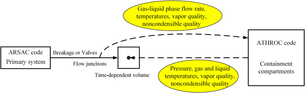
Figure 1. Schematic Diagram of the Coupling Interface between ATHROC and ARSAC when the Breach is on the Primary System Pressure Boundary.
2.2 The interface between the safety injection system and the primary system as the coupling interface
The water sources for the Emergency Core Cooling System (ECCS) include the Reactor Water Storage Tank (RWST) or IRWST, containment sump, and non-passive injection tank. Taking the CPR1000 as an example, in the event of a loss-of-coolant accident causing depressurization of the primary system, the high-pressure injection pump is first activated to inject water from the RWST into the main pipeline. If necessary, water is injected into the main pipeline from the non-passive medium-pressure injection tank. Finally, the low-pressure injection pump is activated to inject water from the RWST into the main pipeline. When the water level in the RWST is too low, the low-pressure injection pump switches to draw water from the containment sump for long-term recirculation cooling. When coupling ARSAC with ATHROC, ATHROC is responsible for modeling the ECCS, and the coupling approach is illustrated in Figure 2. After ARSAC successfully completes a time step, when the ECCS subsystem reaches activation conditions, ARSAC transfers the thermal-hydraulic information of the primary system required by the ECCS (such as pressure and temperature) to ATHROC. ATHROC then performs calculations for the same time step, updating the thermal-hydraulic information of the RWST, containment sump, and injection tank, and transfers the injection flow rate to ARSAC, thus completing one computational cycle. It is worth noting that the non-passive injection tank model still utilizes ARSAC’s built-in ACCUM component for detailed simulation because ATHROC’s injection tank model injects flow directly into the pressure vessel downcomer rather than the main pipeline, and ARSAC’s injection tank model is more mechanistic.
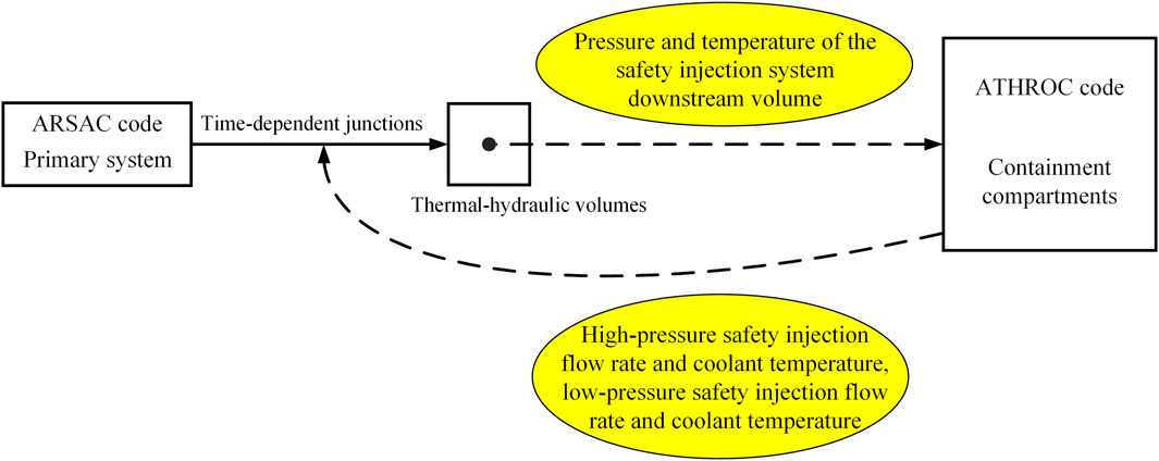
Figure 2. Schematic Diagram of the Coupling Interface between ATHROC and ARSAC when the Interface is between the ECCS and the Primary System.
To couple ATHROC with ARSAC, ATHROC was modified into a subroutine and called within the control loop of ARSAC’s computational subroutine. Data exchange between the programs was achieved through global variables.
3 Demonstration of the coupling method
Based on ARSAC modeling of the Marviken CFT 24 experiment (USNRC, 1982) and utilizing the containment calculation model commonly used for testing in the ATHROC series programs at the Zion Nuclear Power Plant, the coupling of the ARSAC code and ATHROC code was setup for validation and demonstration. The Marviken CFT experiment was conducted at Marviken Power Station which employs a boiling heavy water reactor, while the Zion Nuclear Power plant adopted PWR. The critical flow data of water and steam water mixtures collected in the Marviken CFT experiment can be readily used to assess the two-phase critical flow model of a system code like ARSAC during LOCA analysis, because the input model of the experiment was simple to build (mainly consisting of a large vessel and a pipe) and the experimental data is publicly available (Kim and Kim, 1992). On the other side, the containment model of Zion Nuclear Power Plant was also a frequently used example to demonstrate the modeling capability of integrated safety analysis codes for PWR large dry containment under accident conditions (Brunett, 2014). Therefore, the two models are combined in this paper for validation and demonstration of analyzing highly transient discharge of water-steam mixture into the containment compartments, although it is noted that they were physically unrelated.
3.1 Description of the Marviken experiment
The ARSAC calculation model for the Marviken CFT 24 experiment is shown in Figure 3. The ATHROC calculation model for the large dry containment (with a free volume of 78,927 m3) includes containment compartments and atmospheric surroundings: the cavity, lower compartment, upper compartment, annular compartment, and environment. The Zion Nuclear Power Plant is a Generation II four-loop pressurized water reactor designed by Westinghouse. When the containment pressure exceeds 0.25 MPa, the containment spray pump begins operation 30 s after receiving a high-pressure signal, drawing water from the external Reactor Water Storage Tank (RWST) to spray onto the containment dome. In this test scenario, a significant amount of gas-liquid two-phase mixture released vertically downward from the Marviken CFT 24 pressure vessel located in the upper compartment is discharged into the cavity of the containment (with a free volume of 217 m3). As the Marviken CFT 24 experiment lasts less than 80 s and there is a 30-s delay in the operation of the containment spray pump, the calculation time is extended to 200 s to facilitate a clearer analysis of the containment spray effect and RWST water level changes.
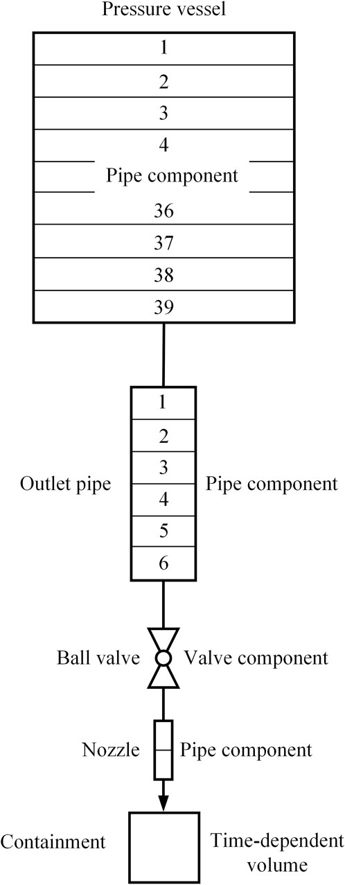
Figure 3. Nodalization of the Marviken CFT 24 experiment in ARSAC.
3.2 Demonstration results
As shown in Figure 4, the release immediately caused pressure to rise in the cavity, reaching a maximum of 0.31 MPa. Due to its large free volume, pressure in the upper compartment increased slowly. As the pressure in the upper compartment of the containment exceeded 0.25 MPa, the containment spray system would be initiated. Figure 5 indicates a rapid increase in gas temperature within the containment, with steam temperature reaching 418 K in the upper compartment by the end of the release. Figure 6 illustrates the cavity rapidly reaching its full water level. Figure 7 compares the integrated flow rate through the breach with the increase in containment fluid mass. Before the containment spray system was activated, the integrated flow rate through the breach matched the increase in containment fluid mass perfectly, indicating reasonable data transfer during the coupled calculations, i.e., the fluid mass from the breach matched the increase in fluid mass within the containment. After the containment spray system was activated, it caused continued increase in fluid mass within the containment, exceeding the integrated flow rate through the breach. This case study demonstrates the successful and reasonable coupling between ATHROC and ARSAC, laying the foundation for comprehensive analysis of both the containment and the primary system.
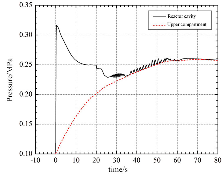
Figure 4. Variation of pressure in the upper compartment and cavity of the containment over time.
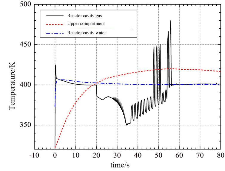
Figure 5. Variation of fluid temperature in the upper compartment and cavity of the containment over time.
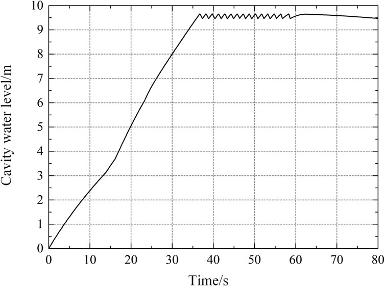
Figure 6. Variation of water level in the containment cavity the over time.
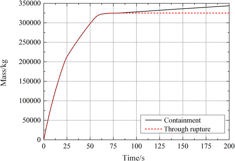
Figure 7. Comparison of the increase in fluid mass within the containment with the integrated flow rate through the rupture.
4 Analysis of the active depressurization measure for CPR1000 in TMLB'
Under accident conditions, maintaining a high-pressure level in the primary system can adversely affect the successful implementation of accident mitigation measures, even leading to severe accidents such as High Pressure Melt Ejection (HPME), threatening the structural integrity of the containment. In situations where the Emergency Core Cooling System (ECCS) is available, prompt depressurization of the primary system allows for effective core cooling to be restored by external cooling water. In scenarios where the ECCS is unavailable, even if core melting is inevitable, depressurization of the primary system can prevent a large amount of molten core material from entering the containment in a jet-like manner, thereby avoiding severe issues such as Direct Containment Heating (DCH) and preserving the structural integrity of the containment. Manual opening of the relief valves of the pressurizer to directly depressurize the primary system when the core outlet temperature exceeds 650°C is a severe accident mitigation measure implemented in CPR1000 nuclear power plants, known as “pressurizer relief extension function”. Primary system fluid is directed through the relief valves of the pressurizer into the relief tank and eventually enters the containment due to the limited capacity of the relief tank. This measure carries some risks in situations where the active low-pressure injection system fails to restore promptly, as it leads to rapid pressurization of the containment alongside depressurization of the primary system. Under such circumstances, it is essential to avoid introducing additional uncertain factors into the containment that could cause further pressure increase, such as hydrogen combustion.
The TMLB’ accident is a type of Station Blackout (SBO) accident sequence in pressurized water reactors, where the auxiliary feedwater pumps also fail. In this accident scenario, the secondary side quickly boils dry after losing auxiliary feedwater. When the core outlet temperature exceeds 650°C, it is assumed that the operators manually open the relief valves of the three pressurizers for active depressurization. The failure of the main pump shaft seals, the creep failure of the heat pipe sections and the pressurizer surge line, as well as the rupture of the steam generator heat transfer tubes, are not considered. The computational model is illustrated in Figure 8, where the blue portion is modeled using ARSAC and the gray portion is modeled using ATHROC.
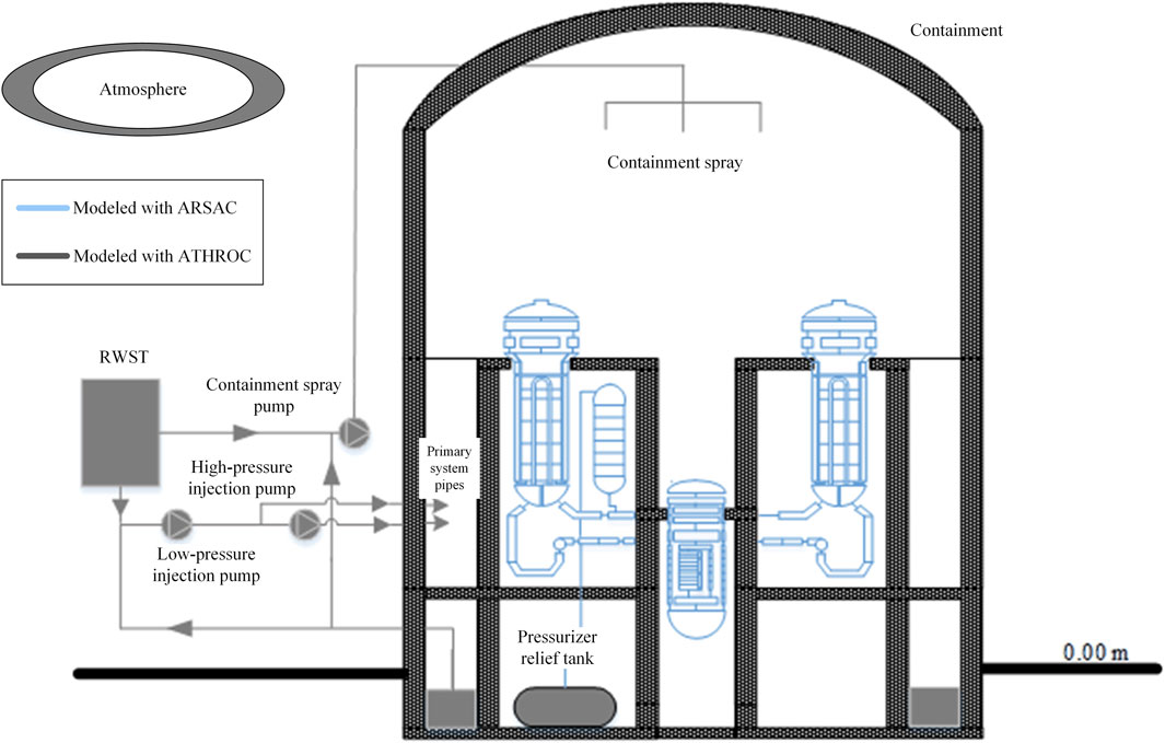
Figure 8. Input model of ATHROC/ARSAC coupled analysis for CPR1000 primary system/containment.
4.1 The effect of active depressurization on the primary system
The variation of pressurizer pressure is shown in Figure 9. Due to the unavailability of the auxiliary feedwater system, the water level on the secondary side of the steam generators continues to decrease, causing the pressure in the primary system to start rising. As the pressure increases, the pressurizer relief valves perform overpressure protection, automatically cycling open and closed to maintain the pressurizer pressure between 16.0 and 17.2 MPa. Subsequently, the operators manually open the relief valves of the three pressurizers, releasing a large amount of steam from the safety valves. As a result, the pressurizer pressure rapidly decreases, and the passive containment cooling system automatically injects water into the primary system.
Figure 9. Variation of pressurizer pressure over time.
As shown in Figure 10, the collapsed water level in the core experienced four decreases before complete uncovering. Approximately 820 s after the secondary side of the steam generators dried up, significant boiling occurred in the core region, marking the first decrease. The pressurizer overflowed during the automatic opening of all relief valves for overpressure protection, causing partial high-temperature single-phase water to discharge from the safety valves and resulting in the second decrease in core collapse water level. Subsequently, steam became the predominant fluid discharged from the safety valves, leading to the third decrease in core collapse water level. When all relief valves of the pressurizer were manually opened, the core collapse water level rapidly decreased for the fourth time until complete exposure. By the time the proactive depressurization measures were taken, the core was nearly completely exposed. About 500 s later, with the injection from the passive containment cooling system, the core water level rapidly increased. Under the influence of injection from the containment cooling system, the core water level exhibited significant fluctuations but did not reach complete exposure. Nonetheless, the possibility of a zirconium-water reaction releasing hydrogen during the accident process is still high.
Figure 10. Variation of collapsed water level in the core over time.
4.2 The effect of active depressurization on the containment
After active depressurization, the pressurizer safety valves forcibly open, leading to the rupture of the depressurization tank due to its limited volume, and the flow discharged through the rupture disk into the containment is shown in Figure 11. The variation of fluid energy entering the containment over time is depicted in Figure 12, which is beneficial for the active depressurization of the primary system but leads to an increase in pressure and temperature within the containment. The variation of pressure at the containment dome after the accident is shown in Figure 13. Prior to the implementation of active depressurization measures, the pressure at the containment dome increases due to the automatic opening of safety valves, reaching a maximum pressure of 0.216 MPa. The active depressurization measures result in a significant amount of high-temperature steam entering the containment through the rupture disk of the depressurization tank, causing a rapid increase in pressure at the containment dome. After 12,000 s post-accident, the pressure in the containment rises to 0.39 MPa, with only 0.12 MPa margin from the containment’s design pressure of 0.52 MPa, and it continues to rise. Lacking the containment spray, the containment is filled with steam with temperatures as high as 130°C, as seen in Figure 14. Due to the inability of the containment spray system to operate, as shown in Figure 15, the water level in the sump is low, and the water temperature exceeds 100°C.
Figure 11. Variation of mass flow rate through the pressurizer relief tank rupture disk over time.
Figure 12. Variation of integrated fluid energy into the containment over time.
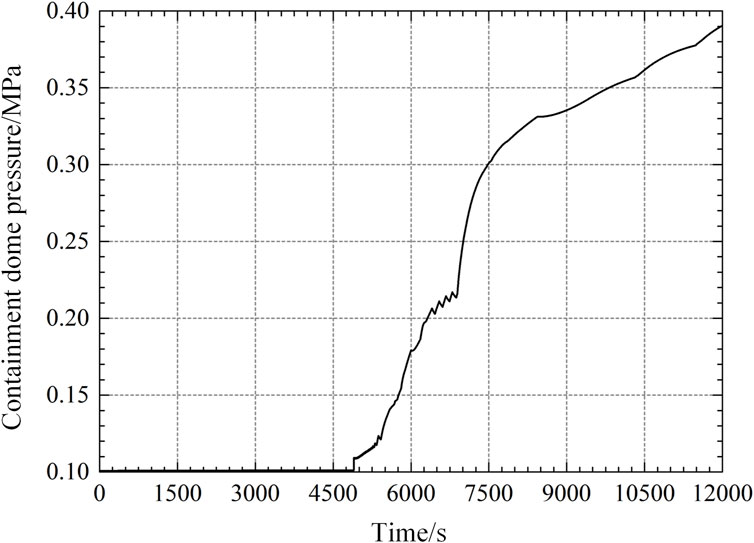
Figure 13. Variation of containment dome pressure over time.
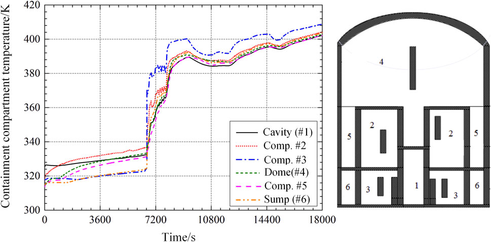
Figure 14. Variation of gas temperature in the containment compartments.
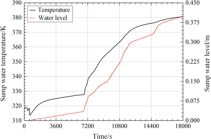
Figure 15. Variation of water temperature and water level in the containment sump.
5 Conclusion
The study investigated the direct coupling method between ATHROC and ARSAC. Apart from the common data transfer of containment pressure and break flow rates, it also enables the transfer of injection flow rates to facilitate the use of ATHROC’s realistic dedicated models of safety systems. By modeling Marviken CFT 24 with ARSAC and simulating the containment compartments with ATHROC, this case was utilized to validate and test the ATHROC/ARSAC coupling program, demonstrating its rationality and showcasing its comprehensive analysis capabilities.
Using the ATHROC/ARSAC coupling program, the impact of extending the function of the pressurizer safety valve on mitigating TMLB’ high-pressure accidents was analyzed. The purpose of this measure is to actively release the heat from the primary system through the pressure safety valves, triggering injection from the accumulator, but the fluid goes directly into the containment compartments. While the proactive opening of the pressurizer safety valve played a positive role in delaying core meltdown, the pressure in the primary system remains relatively high, around 1.8 MPa, making it unfavorable for sustained stable injection from the low-pressure safety injection pump. Hence, it is essential to promptly restore the auxiliary injection system (electric or pneumatic) to further relieve pressure from the primary system.
The extension of the pressurizer’s pressure relief function had adverse effects on the containment, as a large quantity of high-temperature fluid entered the containment compartment through the pressure relief tank. Assuming no hydrogen combustion occurred, the containment pressure had risen to nearly 0.4 MPa. Therefore, to prevent containment overpressure, it is crucial to ensure the proper functioning of the passive hydrogen recombiner.
Data availability statement
The raw data supporting the conclusions of this article will be made available by the authors, without undue reservation.
Author contributions
XW: Writing–original draft, Writing–review and editing. ZZ: Investigation, Software, Writing–original draft. JD: Supervision, Writing–review and editing. YL: Data curation, Writing–review and editing. QL: Methodology, Writing–review and editing. QX: Writing–review and editing. CC: Writing–review and editing. HS: Writing–original draft. YL: Writing–original draft. DS: Writing–original draft. WL: Writing–review and editing.
Funding
The author(s) declare financial support was received for the research, authorship, and/or publication of this article. This work was supported by the Joint Funds of the National Natural Science Foundation of China (U2067210), and the Innovative Scientific Program of China National Nuclear Corporation (2022). The authors declare that this study received funding from China National Nuclear Corporation. The funder was not involved in the study design, collection, analysis, interpretation of data, the writing of this article, or the decision to submit it for publication.
Conflict of interest
The authors declare that the research was conducted in the absence of any commercial or financial relationships that could be construed as a potential conflict of interest.
Publisher’s note
All claims expressed in this article are solely those of the authors and do not necessarily represent those of their affiliated organizations, or those of the publisher, the editors and the reviewers. Any product that may be evaluated in this article, or claim that may be made by its manufacturer, is not guaranteed or endorsed by the publisher.
References
Brunett, A., Denning, R., and Aldemir, T. (2014). A Reassessment of low Probability containment failure Modes and phenomena in a long-term Station Blackout. Nucl. Technol. 186 (2), 198–215. doi:10.13182/nt13-40
Chen, Y., Wu, Y. W., Wang, M. J., Zhang, Y. P., Tan, B., Zhang, D. L., et al. (2018). Development of a multi-compartment containment code for advanced PWR plant. Nucl. Eng. Des. 334, 75–89. doi:10.1016/j.nucengdes.2018.05.001
Chung, B. D., Jeong, J. J., and Lee, W. J. (1998) “MARS 1.3 system analysis code coupling with CONTEMPT4/MOD5/PCCS containment analysis code using dynamic link library,” in Proceedings of the Korean nuclear Society autumn meeting, 29–30.
Chung, B. D., Jo, J. J., and Rohatgi, U. S. (2001). RELAP5/MOD3.2.2 coupling with CONTAIN 2.0 containment analysis code using Dynamic Link Library. Washington, DC: CAMP Meeting.
Deng, J., Ding, S., Li, Z., Huang, T., Wu, D., Wang, J., et al. (2021). The development of ARSAC for modeling nuclear power plant system. Prog. Nucl. Energy 140, 103880. doi:10.1016/j.pnucene.2021.103880
Fletcher, C. D., and Schultz, R. R. (1992). RELAP5/MOD3 code manual (No. NUREG/CR-5535-Vol. 5; EGG-2596-Vol. 5). Nuclear Regulatory Commission, Washington, DC (United States). Div. Of systems research; EG and G Idaho. Idaho Falls, ID (United States): Inc.
Gauntt, R. O., Cole, R. K., Erickson, C. M., Gido, R. G., Gasser, R. D., Rodriguez, S. B., et al. (2000). MELCOR computer code manuals. Sandia Natl. Lab. NUREG/CR 6119, 785.
Gavrilas, M., Hejzlar, P., Todreas, N. E., and Driscoll, M. J. (1996). Gothic code evaluation of alternative passive containment cooling features. Nucl. Eng. Des. 166 (3), 427–442. doi:10.1016/s0029-5493(96)01259-9
Kim, K., and Kim, H. J. (1992). Assessment of RELAP5/MOD2 critical flow model using Marviken Test Data 15 and 24. NUREG/IA-0086. Washington, DC: Nuclear Regulatory Commission. Office of Nuclear Regulatory Research
Kwon, Y. M., Park, C. E., and Song, J. H. (1998). Comparative mass and energy release and containment analyses for a large-break loss-of-coolant accident using RELAP5/CONTEMPT4 and design computer codes. Nucl. Technol. 122 (3), 295–305. doi:10.13182/NT98-A2871
Murata, K. K., Carroll, D. E., Washington, K. E., Gelbard, F., Valdez, G. D., Williams, D. C., et al. (1989). User's manual for CONTAIN 1.1: a computer code for severe nuclear reactor accident containment analysis No. NUREG/CR-5026; SAND-87-2309. Albuquerque, NM (United States): Sandia National Lab SNL-NM.
Park, C. E., Lee, G. H., Lee, W. J., Chung, B. D., and Lee, S. Y. (1994). “Development of a merged version of RELAP5/MOD3 and CONTEMPT4/MOD5,” in Proceedings of the KNS spring meeting.
Rodriguez, S. (2002). Using the coupled MELCOR-RELAP5 codes for simulation of the Edward’s pipe. Albuquerque, NM, USA: Sandia National Laboratories.
Schulz, T. L. (2006). Westinghouse AP1000 advanced passive plant. Nucl. Eng. Des. 236 (14-16), 1547–1557. doi:10.1016/j.nucengdes.2006.03.049
Smith, K., Baratta, A. J., and Miller, J. (1994) “Simulation of coupled primary system and containment response using RELAP5 and CONTAIN on a Multiprocessor computer,” in International Conference on New Trends in nuclear system Thermohydraulics.
Smith, K., Baratta, A. J., and Robinson, G. E. (1995). Coupled relap5 and contain accident analysis using PVM. Nucl. Saf. 36 (1), 94–108.
Smith, K. A. (1993) “Multi-processor based accident using PVM,” in SIAM Conference on Parallel processing for Scientific computing.
Wheat, L. L., Wagner, R. J., Niederauer, G. F., and Obenchain, C. F. (1975). Contempt-LT: a computer program for predicting containment pressure-temperature response to a loss-of-coolant accident (No. ANCR-1219). Idaho Falls, ID (United States): Aerojet Nuclear Co.
Williams, E. S., Martin, R., Gandrille, P., Meireles, R., Prior, R., Henry, C., et al. (2008). “Recent revisions to MAAP4 for US EPR severe accident applications,” in Proceedings of the ICAPP 2008 Conference (CA: Anaheim).
Keywords: best-estimate code, containment, code coupling, active depressurization measure4, TMLB’ accident
Citation: Wu X, Zheng Z, Deng J, Liu Y, Lu Q, Xiang Q, Chen C, Sun H, Lu Y, Shen D and Li W (2024) Coupling of the best-estimate system code and containment analysis code and its application to TMLB’ accident. Front. Energy Res. 12:1436245. doi: 10.3389/fenrg.2024.1436245
Received: 21 May 2024; Accepted: 08 July 2024;
Published: 30 July 2024.
Edited by:
Jiankai Yu, Massachusetts Institute of Technology, United StatesReviewed by:
Ivo Kljenak, Institut Jožef Stefan (IJS), SloveniaFulong Zhao, Harbin Engineering University, China
Copyright © 2024 Wu, Zheng, Deng, Liu, Lu, Xiang, Chen, Sun, Lu, Shen and Li. This is an open-access article distributed under the terms of the Creative Commons Attribution License (CC BY). The use, distribution or reproduction in other forums is permitted, provided the original author(s) and the copyright owner(s) are credited and that the original publication in this journal is cited, in accordance with accepted academic practice. No use, distribution or reproduction is permitted which does not comply with these terms.
*Correspondence: Xiaoli Wu, d3V4aWFvbGxpZG9uZ2xpQGdtYWlsLmNvbQ==