- 1ENSIT/LISIER Laboratory, University of Tunis, Tunis, Tunisia
- 2College of Computer and Information Sciences, Prince Sultan University, Riyadh, Saudi Arabia
- 3Automated Systems and Soft Computing Lab (ASSCL), Prince Sultan University, Riyadh, Saudi Arabia
- 4Faculty of Computers and Artificial Intelligence, Benha University, Benha, Egypt
- 5Department of Electrical Engineering, College of Engineering, University of Baghdad, Baghdad, Iraq
- 6Department of Electronics and Communication Engineering, Uruk University, Baghdad, Iraq
This article presents a proportional-integral sliding mode control (PI-SMC) approach for a two-mass variable speed wind turbine (VSWT) system. Most studies on wind turbines typically focus mainly on the electromagnetic part of the generators, or even on the high-speed part, considering the shaft stiffness as negligible. However, the generator torque is actually driven by the aerodynamic torque, and a two-mass system like the one studied here plays the role of a transmission element for this power. To address this challenge, the problem of low power generation resulting from wind speed variability is tackled by designing a PI-SMC control law, capable of controlling the mechanical turbine model that optimizes power and torque by tracking the maximum power point (MPPT) for rotational speed and aerodynamic power. To validate the developed theoretical results, an application of the wind turbine system is simulated in Matlab/Simulink, for a particular case. The control used is capable of satisfying the dynamic performance of the systems.
1 Introduction
Renewable energy is essential for creating a sustainable and environmentally friendly future, as it significantly reduces greenhouse gas emissions and dependence on finite fossil fuels. By harnessing natural resources such as sunlight, wind, and water, renewable energy technologies mitigate the adverse effects of climate change, improve air quality, and enhance energy security (Kamal and Ibrahim, 2018). Furthermore, the transition to renewable energy fosters economic growth through the creation of green jobs and the development of new industries. This shift not only ensures a more resilient and diverse energy supply but also promotes innovation and long-term environmental stewardship, essential for the well-being of current and future generations. Wind energy has become increasing interest in recent years as a promising and sustainable renewable energy source. Recent research has highlighted the growing importance of wind energy as a clean and renewable power source, particularly in light of concerns about climate change and natural resource depletion (Martin et al., 2023). With the rapid evolution of wind turbine technology, it has become crucial to design more powerful and intelligent control systems to improve their performance, reduce costs, and increase reliability (Alsyouf, 2011; Dhanraj et al., 2022a; Abdelrahim and Almakhles, 2023; Jaikrishna et al., 2023; Sethi et al., 2023). To achieve maximum energy extraction from the wind, variable-speed wind turbines (VSWT) have been developed to operate over a wide range of speeds. However, the significant challenge of controlling the electrical generator in response to wind speed fluctuations remains (Dhanraj et al., 2022b; Chang et al., 2022).
In the field of wind energy conversion technologies, various approaches have been explored in recent years to optimize aerodynamic power. Classical controllers, such as the proportional-integral-derivative control (PID), have been widely used, as evidenced by numerous studies (Yang et al., 2017; Lisitsyn and Zadorozhnaya, 2019; Alqudah, 2020; Frikh et al., 2021). While many control approaches face issues like the runaway phenomenon, research has proposed enhancements to address these challenges. Optimal control methods like Linear Quadratic Regulator (LQR) and Linear Quadratic Gaussian have also been employed (Jeon and Paek, 2021; Zgarni and ElAmraoui, 2021; El Beshbichi et al., 2022). However, recent studies have indicated that these methods do not show improved performance compared to other controllers. On the other hand, Sliding Mode Control (SMC), a crucial transient mode for Variable Structure Control, has been utilized to improve robustness (Lu and Spurgeon, 1999; Utkin, 2004; Sira-Ramírez, 2015; Levant and Livne, 2016). The original work on SMC was primarily conducted by Soviet control experts (Petrov et al., 1964; Itkis, 1976; Zinober, 1994).
Modern wind turbines incorporate sophisticated power electronics to ensure efficient generator control and operation compatible with the electrical system (Ko et al., 2008; Durgam et al., 2022; Yahyaoui et al., 2022; Kesavan et al., 2024). However, recent studies have emphasized the importance of developing advanced control strategies to mitigate uncertainties in wind turbine modeling (Dao et al., 2020; Fekih et al., 2022; Gonzaga et al., 2022). These strategies aim to ensure an optimized and stable operational state despite the erratic and inconsistent nature of the energy source, while considering the Betz limit constraint (Gbadega and Saha, 2021). Overall, the development of robust control mechanisms that account for uncertainties in wind turbine modeling and enhance performance is essential for the successful implementation of wind energy conversion systems.
Therefore, to achieve the optimal production point of the wind system, a nonlinear control approach is required. Several robust control techniques have been developed to optimize desired wind turbine parameters, especially aerodynamic power and rotor speed (Shaker and Patton, 2014; Azar and Serrano, 2015; Gao and Gao, 2016; Meghni et al., 2017; Meghni et al., 2018; Abdelmalek et al., 2018; Gorripotu et al., 2019; Yin et al., 2019; Jiao et al., 2020; Saha et al., 2022). A promising control alternative is SMC, which has been proposed in numerous studies (Torchani et al., 2016; Ammar et al., 2019; Berrada et al., 2020; Colombo et al., 2020; Deng and Xu, 2022). In this context, improving effective control approaches for wind turbine systems is crucial to enhance their performance and energy generation efficiency. Wind speed variability poses a significant challenge to wind power generation. This paper addresses this challenge by introducing a PI-SMC approach for a VSWT to enhance its aerodynamic power. The primary goal of this work is to create a control strategy that optimizes power and torque through Maximum Power Point Tracking (MPPT) for rotational speed and aerodynamic power. Developing a nonlinear model of wind turbine dynamics that considers wind speed variability is crucial. The PI-SMC technique provides a reliable solution to address wind power generation challenges and enhance wind turbine system performance. This technique utilizes SMC for MPPT and PID for system output stabilization (Singh et al., 2017; Xia et al., 2021; Chatri et al., 2022; Chehaidia et al., 2022; Periyanayagam and Joo, 2022).
The development of a SMC strategy for a VSWT is critical in achieving maximum aerodynamic power. The surface of the SMC plays a vital role in minimizing the tracking error and reducing the control system’s chattering. The SMC technique also offers robustness to system uncertainties, making it an ideal control strategy for wind turbines. By using a SMC approach, the wind turbine can reach MPPT with high accuracy, thus ensuring the optimal energy production efficiency. By optimizing power and torque, the wind turbines performance is significantly improved, making it a reliable source of renewable energy.
The purpose of this article is to establish a PI-SMC control for VSWT system. The key point is to demonstrate the ability of this control to control the system from an arbitrary initial condition in a relatively short time while preserving system stability. The turbine is considered as a two-mass mechanical transmission system, which imposes a more or less slow response. Additionally, the main control is materialized through aerodynamic power, which tends to drive the system into an imposing dynamic to rotate the generator shaft. The generator, through its electromagnetic power, plays the role of a disturbance opposing the control that gave rise to it.
This work is arranged as follows: Section 2 will present the turbine model using development of the aerodynamic power relations and the power coefficient of the turbine as a function of wind speed and power. Subsequently, in Section 3, the modeling of the mechanical part of the turbine will be established. The aerodynamic turbine is considered as a two-mass gear train system, a transmission model. This modeling is based on different equations of the system’s dynamics, which will then allow for the establishment of a state-space modeling. The objectives of the proposed control will be mentioned in Section 4, specifying the parameters we will work on and potentially the commands to be developed for the turbine system. In Section 5, the proposed SMC scheme for the two-mass transmission turbine system will be established, along with the verification of the system’s stability using this control. The integration of the Proportional integrator controller component with the SMC, as well as the stability verification, will be addressed in Section 6. To apply the theory of this work, numerical simulations of the turbine system using various controls, including the PI-SMC control, will be presented in Section 7. Lastly, a conclusion will be given in Section 8.
2 Wind turbine model
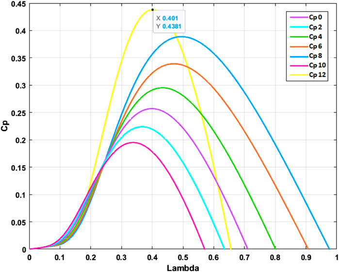
As established in Zheng et al. (2009), the wind power across area
where
The rotor radius is denoted by the symbol
To calculate the power coefficient, one must divide a certain ratio:
The power that the wind turbine receives can be stated as follows:
where
The
with
3 Mechanical part of the turbine modelling
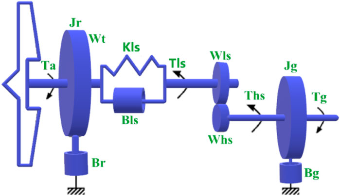
In this section, we describe the mechanical modelling of the wind turbine system, consisting mainly of the turbine and the gearbox, as shown in Figure 2. The two-mass system is the most used approach to express a wind turbine system (Boukhezzar and Siguerdidjane, 2011; Habibi et al., 2017), which comprises the blades and gearbox. As a result, the proposed two-mass model consists of two main rotors, which represent the wind turbine and the generator. Between these two parts, a flexible shaft is mounted to connect the two components of the wind turbine, namely the aerodynamic turbine side and the generator side. Furthermore, on the generator side, the modeling is based on the arrangement of the moment of inertia of the gears and the stiffness of the high-speed shaft
This system is used to further model the wind turbine and establish a mathematical dynamical model of the control system, which is applicable to wind turbines of different dimensions.
The similar approach is applied to the multiplier, and the different relationships are expressed as follows after establishing Eqs 5, 6 and by applying various energy principles to the rotor and Newton’s second law, we obtain:
where
The low speed shaft results from the torsion and friction effects due to the difference between
where
We consider that the moment of inertia
The dynamics of the rotor is characterized by the motion of the high-speed shaft torque
with
where
After some calculations and using the Eqs 7, 9, 11, we obtain the following state system describing the multi-input/multi-output system:
where
4 Objectives of the control
Wind speed does not follow a constant pattern, but rather varies randomly. Therefore, it is essential to optimize the process of wind turbines during times when the wind speed is minimal or insufficient. The goal of wind energy systems is to maintain the turbine at nominal speed to ensure profitable and efficient power generation. Therefore, it is crucial to take into account the mechanical pieces of the turbine, namely the gearbox and the blades, in order to maximize the aerodynamic power.
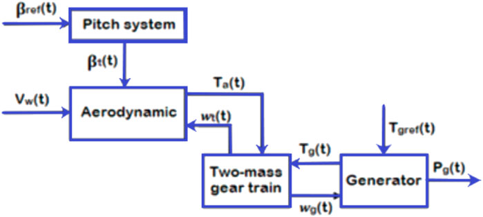
Figure 3 shows the control strategy principle applied to the turbine system with pitch control optimization. It illustrates the arrangement of the different parts of the transmission chain that receives the kinetic energy of the wind and converts it into electromechanical energy. Initially, the aerodynamic turbine receives the wind speed
The aim is to use PI-SMC scheme to command the wind turbine system. However, MPPT problems are always studied in close connection with the electromechanical generator without involving the aerodynamic part of the turbine when modeling and especially in optimizing the obtained electrical power. Since the turbine part, shaft, and gearbox consist of purely mechanical elements, it responds relatively slowly compared to the electrical part. This necessitates the use of the chosen control. Furthermore, the classical PI control is preferred due to its relatively simple implementation and tuning, which makes it commonly used in many applications. Moreover, precision is well controlled through the integral component, which corrects static errors and ensures high system accuracy. Additionally, stabilization is fast due to the proportional action of the system, minimizing real-time errors.
Since the turbine system is highly influenced by highly variable dynamics caused by the varying wind speed model, which is stochastically unpredictable, it is imperative to subject the characteristics of the PI controller to a command that can guarantee insensitivity to external disturbances and parameter variations that may arise in the turbine system. For this purpose, the use of SMC control ensures robustness, especially in the presence of uncertainties. In terms of control, SMC also allows precise reference tracking even under external disturbances, particularly the random wind speed and the internal structure, such as the shaft stiffness coefficient
Overall, the automatic adaptability of control gains based on changing system conditions improves its ability to adjust to variations.
The aerodynamic power is maximized through its torque coefficient
The optimal tip-speed ratio
The value of
Then the Eq. 8 is verified if the rotor speed
Using the Eqs 2, 4, the
with
Since the rotation speed is the control parameter to be controlled, we can write the previous expressions as follows:
with
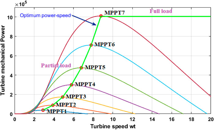
Using Eqs 13–17, the aim of this section is to achieve an optimal rotational speed that produces the maximum power output without exceeding the nominal power rating of the turbine. Thus, it is crucial to regulate the turbine’s speed to maintain this condition as shown in Figure 4. In order to capture the maximum power from the wind, it is necessary to keep the pitch angle at zero, which provides an optimal orientation to the wind speed.
Generally, in the design of control systems for wind energy systems, the focus is mainly on the modeling and control of the electrical part, particularly the asynchronous machine, rather than on the detailed modeling of the mechanical part (turbine and gearbox). The reason is that the mechanical dynamics usually have a much slower time constant than the electrical dynamics, which allows for simplifying assumptions on the mechanical part without significantly affecting the performance of the overall control system.
In our study, we focused on the modeling of the aerodynamic part of the wind turbine in order to design our PI-SMC control aimed at optimizing the generator’s power and torque. This approach allowed us to focus on the most critical aspect of the system, namely the maximum extraction of wind power, without the need to model the mechanical part in detail.
Although we did not specifically address the implementation of MPPT in this article, this technique is generally used to track the maximum power point by adjusting the turbine’s rotational speed according to the wind speed.
5 Sliding mode control design
In this section, the design of SMC for the wind turbine system is provided. Firstly, the rotational speed is controlled to maintain an optimal value. The main aim is to increase the Cp as close as possible to the Betz limit by optimizing the beta and lambda parameters. Secondly, the mechanical system of the turbine, modelled as a two-mass system, is controlled by SMC to obtain an optimal electromagnetic torque that generates sufficient power to enable the generator to produce the optimal electrical energy. In previous research, J. J. Slotine has proposed a sliding surface (Slotine et al., 1986; Slotine and Hong, 1986; Kelkoul and Boumediene, 2021; Yao et al., 2021) that ensures the attraction of a variable to its optimal or predetermined reference value.
The sliding manifold is defined as:
with
The sliding surface given in Eq. 18, is given as:
Differentiating the expression of S, we obtain:
Substituting Eq. 22 in Eq. 7, we obtain:
with
Using Eqs 21, 24 the expression of
In sliding mode, we have the following conditions:
Using the Eq. 25 to verify the Eq. 26 and to preserve
with
The equivalent control, given in Eq. 28, will ensure that the system tracks the desired reference value. The nonlinear control will guarantee the system reaches the sliding surface and remains attractive to it. In fact this aspect of the SMC will require the system’s dynamics to stay on the sliding surface previously defined by tracking the selected error value.
The sign function is commonly used to represent this aspect, as shown below:
Combining Eqs 27, 29 one obtains the following Eq. 30 describing the expression of the SMC:
To verify the stability of the wind turbine system using the Lyapunov function, we need to first define a candidate Lyapunov function
Condition 1:
Condition 2:
Condition 3:
Assuming
This function meets the first two conditions of a Lyapunov function.
To verify the third condition, we need to compute
Substituting the expression for
Substituting the expression for
Simplifying and using the fact that
Checking Eqs 31–35 the is negative semi-definite, and the other terms are all positive. Therefore, it can be determined the system is globally asymptotically stable, it indicates the trajectories converge to the sliding surface and remain on it.
6 PI-SMC design
Our control strategy uses PI-SMC to track the maximum power trajectory. Subsequently, the PI-SMC operating algorithm is designed based on the aerodynamic model of the wind turbine, by defining an appropriate sliding surface
The numerical values of the PI-SMC controller parameters have been selected based on an analysis of the wind turbine aerodynamic model, as well as in-depth simulations of the overall system. This iterative process of parameter tuning has allowed obtaining good performance in terms of MPPT, disturbance rejection and system stability.
Using the SMC strategy, we can integrate the PI controller into the sliding surface expression to obtain improved control of the wind turbine system. Similarly, as presented in the previous section, the sliding surface is given by Eqs 19, 20. To integrate the PI, we add an integral term to the sliding surface as follows:
where
The time derivative of the sliding surface, given in Eq. 36, is obtained as
Substituting from Eq. 10 and
where
The control input is given by:
where
Substituting Eq. 7 into Eq. 39, we obtain Eq. 40:
To investigate the stability of the system, the Lyapunov function and its derivative are given in Eq. 41 and Eq. 42 as follow:
Taking the
Using the inequality
Since
7 Numerical simulation and results
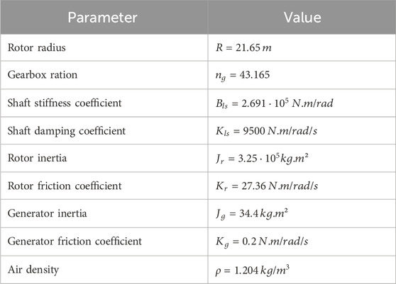
To evaluate the proposed control performance on the two-mass gear train model, simulations will be conducted in the Matlab/Simulink environment. Simulation results will be presented through a series of figures, showcasing the behavior of the multivariable system under PI-SMC. The parameters of turbine system are given in Table 1:
Using the values of the turbine parameters in Table 2 and Eq. 12, we obtain the following state equation:
Final simulation time:
Simulation step:
Initial condition:
Control parameter values
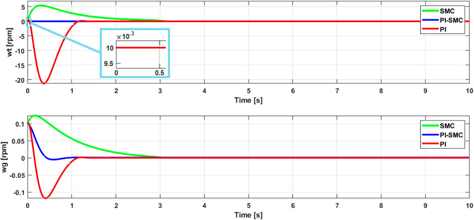
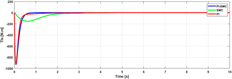
Figures 5, 6 present the evolution of the state variables
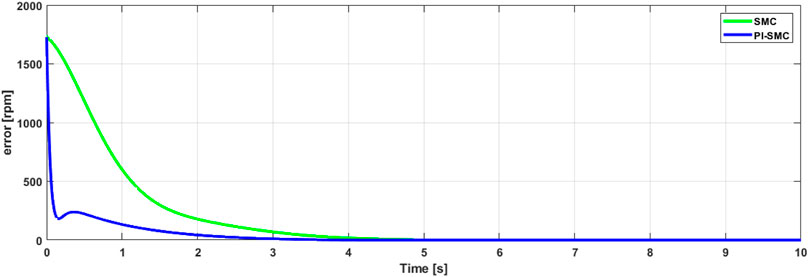
The evolution of the sliding surface, which shows the fluctuation of the rotor speed error controlled by its optimal reference value, is presented in Figure 8. The simulations demonstrate the controller’s effectiveness in mitigating deviations between the system’s behavior
Moreover, these simulations demonstrate a stable convergence of the sliding mode system in both cases. The evolution of the norm of the sliding surface verifies the robustness of the control by converging to zero in a relatively short time, thus showing the control’s ability to eliminate the error between the rotation speed and its optimal value. This demonstrates the effectiveness of the proposed approach in solving the windup problem that can be generated by classical control systems such as PID, if used alone.
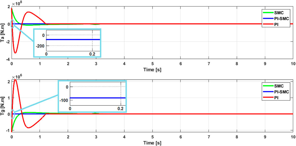
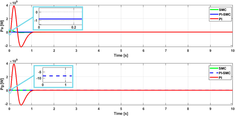
The results of the aerodynamic and generator power control are presented in Figure 9, respectively. These figures depict that the proposed control strategy is satisfactory, i.e., the generator power is sufficient and reaches the objective through the MPPT control strategy. The behavior of the two powers shows good convergence in a short time, which proves the robustness of the PI-SMC. The aerodynamic power figure is characteristic of a slow mechanical system, but the convergence is fast even in the presence of chattering. Despite the randomness of the wind and turbine rotation, the speed variation is controlled by MPPT and provides excellent control responses through the generator power scheme.
The strategy used in the simulation section is essentially based on the behavior of the PI-SMC controls of the various turbine system variables. That is to say, instead of following a classical servo control of the system variables with respect to their references, we have designed the control in such a way that to track the evolution of the control resulting from the dynamic behavior of the system. The simulations have shown us typical sliding mode figures and a transient behavior well adapted to the PI controller. The stability of the system is verified each time. The performance of the dynamic behavior of the PI-SMC controlled system in terms of accuracy and speed is also well verified by a response time of
In this part, we will perform a test to validate the proposed PI-SMC control with respect to other controls used in the control of wind turbines and in particular the two-mass models. In the literature, several control approaches have been explored, in this work, we have opted for the model predictive control (MPC) and the LQR. Several authors have proposed works on the LQR regulator (Haneesh and Raghunathan, 2021; Didier et al., 2024; Wang et al., 2024) and the MPC control (Gaamouche et al., 2020; Moness and Moustafa, 2020; Jiang et al., 2023).
Indeed, according to the literature, both LQR and MPC controls have shown efficiency and optimization in the control management of wind turbines. On the one hand, as a linear quadratic regulation method, the LQR allows high performance for the wind turbine system in the presence of disturbances, namely sudden changes in wind. The servomechanism of the wind turbine variables, primarily the rotor speed and the blade pitch angle, aims to maximize the power. On the other hand, the MPC control uses a predictive model for the wind turbine, in order, to anticipate the behavior of the future dynamics and subsequently calculate the optimal control strategy over a sliding horizon. This control technique allows for appropriate management of the turbine while maximizing production.
The values of the MPC control parameters, are given as:
Prediction horizon:
Control horizon:
State error weighting matrix:
Control variation weighting matrix:
Reference to follow:
where
The LQR regulator parameters, are given as:
State weighting matrix:
Control weighting matrix:
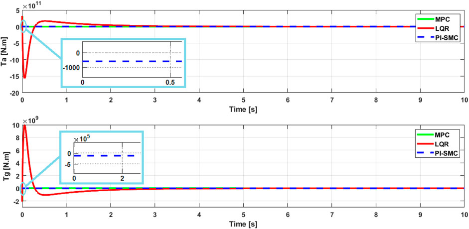
In Figures 10, 11, the shapes of the curves show a typical behavior of the controls. The simulations are performed with the initial conditions given earlier. The results show that all the curves are stable and converge in a relatively short time of
This series of simulations will demonstrate the ability of the controls to overcome constraint perturbations, namely parameter variations and external disturbances, such as changes in wind speed
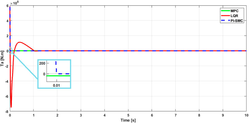
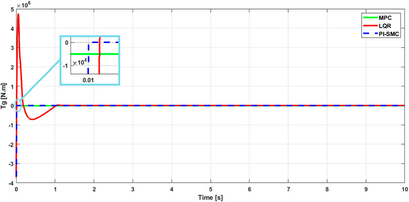
In Figure 12, the behavior of the aerodynamic torque and generator torque controls is very stable and typical. However, the LQR control presents a settling time of
The PI-SMC control shows a fast behavior and, most importantly, it has maintained the same settling time of
In this section we move on to the second test, which consists of evaluating the different MPC, LQR and PI-SMC controls by varying the wind speed
Figures 13, 14 show the behavior of the PI-SMC control compared to the MPC and LQR controls. Each figure presents the simulation of each control with the 3 wind speed values of
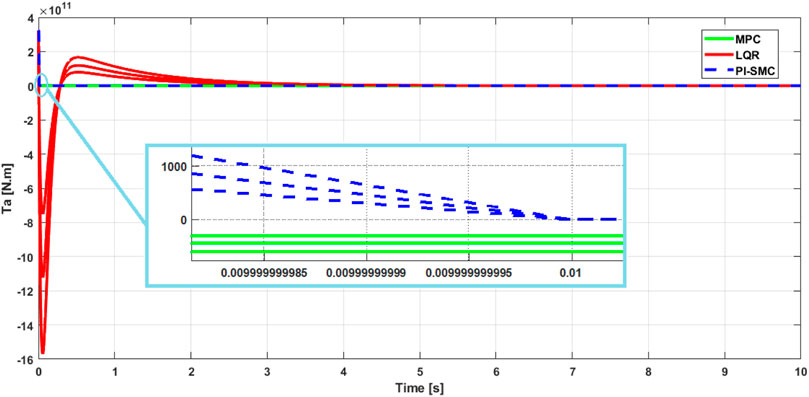
Figure 13. Aerodynamic torque: Responses of the controls for the aerodynamic torque for different wind speed values
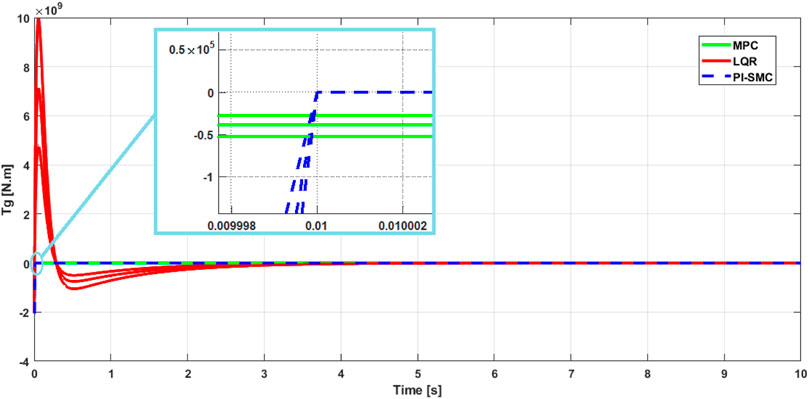
Figure 14. Generator power: Responses of the controls for the generator torque for different wind speed values
Overall, the key strengths of our approach are its robustness and the high accuracy. However, the major downsides of SMC in general are the complexity of implementation and sensitivity to internal disturbances in general. Additionally, the problem of actuator windup remains a drawback of the PI control. Nevertheless, we acknowledge that other control approaches, such as the fuzzy controllers or artificial intelligence techniques, may also be effective in certain specific situations or for particular applications.
8 Conclusion
The objective of this study was to develop and analyze a control strategy for a wind turbine system that could optimize power output while minimizing electromagnetic torque variations. To achieve this, a PI-SMC (Proportional-Integral Sliding Mode Control) approach was implemented and evaluated. Specifically, the MPPT (Maximum Power Point Tracking) technique was used to ensure a fast and accurate coincidence between the turbine speed and reference speed. The PI-SMC approach was used to define a sliding surface representing the error between these speeds and systematically eliminate the chattering phenomenon and windup that often occur in traditional PID controllers.
The results showed that the proposed PI-SMC control strategy was effective in correcting deviations between the system behavior and its reference values. The PI-SMC exhibited typical SMC characteristics, including robustness to mechanical variations, insensitivity to disturbances, and quick convergence. This approach was found to be superior to classical control systems like PID, which are prone to generating windup problems. Overall, the proposed PI-SMC control strategy was shown to be effective in optimizing the power output of the wind turbine system while minimizing electromagnetic torque variations. The approach was robust and stable, and maintained good convergence even in the presence of parametric variations and external disturbances.
However, the study also identified limitations of the PI-SMC strategy. It may not be suitable for wind turbine systems with large delays or significant nonlinearities, as these can make it more difficult to achieve the desired control performance. Ultimately, the PI-SMC is not always the most efficient or optimal control solution for every wind turbine system and other control techniques may be more appropriate depending on the specific application and requirements. Consequently, it would be interesting to integrate other optimal and intelligent control techniques into this control strategy to better manage the PI-SMC control parameters and subsequently optimize its performance.
Data availability statement
The original contributions presented in the study are included in the article/Supplementary Material, further inquiries can be directed to the corresponding author.
Author contributions
BT: Conceptualization, Formal Analysis, Methodology, Resources, Software, Visualization, Writing–original draft, Writing–review and editing. AA: Conceptualization, Formal Analysis, Investigation, Methodology, Supervision, Validation, Writing–original draft, Writing–review and editing. SA: Formal Analysis, Investigation, Methodology, Resources, Validation, Visualization, Writing–review and editing. AM: Formal Analysis, Funding acquisition, Investigation, Methodology, Resources, Validation, Writing–review and editing. II: Formal Analysis, Investigation, Methodology, Resources, Validation, Visualization, Writing–review and editing.
Funding
The author(s) declare that financial support was received for the research, authorship, and/or publication of this article. This research was funded by Prince Sultan University, Riyadh, Saudi Arabia. This research was also supported by the Automated Systems and Soft Computing Lab (ASSCL), Prince Sultan University, Riyadh, Saudi Arabia.
Acknowledgments
The authors would like to thank Prince Sultan University, Riyadh, Saudi Arabia, for support with the article processing charges (APC) of this publication. The authors specially acknowledge the Automated Systems and Soft Computing Lab (ASSCL) at Prince Sultan University, Riyadh, Saudi Arabia. The authors wish to acknowledge the editor and reviewers for their insightful comments, which have improved the quality of this publication.
Conflict of interest
The authors declare that the research was conducted in the absence of any commercial or financial relationships that could be construed as a potential conflict of interest.
Publisher’s note
All claims expressed in this article are solely those of the authors and do not necessarily represent those of their affiliated organizations, or those of the publisher, the editors and the reviewers. Any product that may be evaluated in this article, or claim that may be made by its manufacturer, is not guaranteed or endorsed by the publisher.
References
Abdelmalek, S., Azar, A. T., and Dib, D. (2018). A novel actuator fault-tolerant control strategy of DFIG-based wind turbines using Takagi-Sugeno Multiple models. Int. J. Control, Automation Syst. 16 (3), 1415–1424. doi:10.1007/s12555-017-0320-y
Abdelrahim, M., and Almakhles, D. (2023). Output feedback stabilization of doubly fed induction generator wind turbines under event-triggered implementations. J. Sens. Actuator Netw. 12 (5), 64. doi:10.3390/jsan12050064
Alami, H., Ziani, E., and Bossoufi, B. (2016). Speed control of the doubly fed induction generator applied to a wind system. J. Theor. Appl. Inf. Technol. 83 (3), 426–433.
Alqudah, A. (2020). Controlling of wind turbine generator system based on genetic fuzzy-PID controller. Int. J. Adv. Trends Comput. Sci. Eng. 9 (1), 409–425. doi:10.30534/ijatcse/2020/58912020
Alsyouf, I. (2011). Wind energy system reliability and maintainability, and operation and maintenance strategies. Wind Energy Syst., 303–328. doi:10.1533/9780857090638.3.303
Ammar, H. H., Azar, A. T., Shalaby, R., and Mahmoud, M. I. (2019). Metaheuristic optimization of fractional order incremental conductance (FO-INC) maximum power point tracking (MPPT). Complexity 2019, 1–13. doi:10.1155/2019/7687891
Azar, A. T., and Serrano, F. E. (2015). “Stabilization and control of mechanical systems with backlash,” in Advanced intelligent control engineering and automation, advances in computational intelligence and robotics (ACIR) book series, USA: IGI-global.
Behnamgol, V., and Vali, A. R. (2015). Terminal sliding mode control for nonlinear systems with both matched and unmatched uncertainties. IJEEE 11 (2), 109–117.
Berrada, Y., and Boumhidi, I. (2020). New structure of sliding mode control for variable speed wind turbine. IFAC J. Syst. Control 14, 100113. doi:10.1016/j.ifacsc.2020.100113
Boukhezzar, B., and Siguerdidjane, H. (2011). Nonlinear control of a variable-speed wind turbine using a two-mass model. IEEE Trans. Energy Convers. 26 (1), 149–162. doi:10.1109/tec.2010.2090155
Chang, C. C. W., Ding, T. J., Ping, T. J., Chao, K. C., and Bhuiyan, M. A. S. (2022). Getting more from the wind: recent advancements and challenges in generators development for wind turbines. Sustain. Energy Technol. Assessments 53 (Part C), 1027311.
Chatri, C., Ouassaid, M., Labbadi, M., and Errami, Y. (2022). Integral-type terminal sliding mode control approach for wind energy conversion system with uncertainties. Comput. Electr. Eng. 99, 107775. doi:10.1016/j.compeleceng.2022.107775
Chehaidia, S. E., Kherfane, H., Cherif, H., Boukhezzar, B., Kadi, L., Chojaa, H., et al. (2022). Robust nonlinear terminal integral sliding mode torque control for wind turbines considering uncertainties. IFAC-PapersOnLine 55 (12), 228–233. doi:10.1016/j.ifacol.2022.07.316
Colombo, L., Corradini, M. L., Ippoliti, G., and Orlando, G. (2020). Pitch angle control of a wind turbine operating above the rated wind speed: a sliding mode control approach. ISA Trans. 96, 95–102. doi:10.1016/j.isatra.2019.07.002
Dao, C. D., Kazemtabrizi, B., and Crabtree, C. J. (2020). Offshore wind turbine reliability and operational simulation under uncertainties. Wind Energy 23 (10), 1919–1938. doi:10.1002/we.2526
Deng, Z., and Xu, C. (2022). Frequency regulation of power systems with a wind farm by sliding-mode-based design. IEEE/CAA J. Automatica Sinica 9 (11), 1980–1989. doi:10.1109/jas.2022.105407
Dhanraj, J. A., Alkhawaldeh, R. S., Van De, P., Sugumaran, V., Ali, N., Lakshmaiya, N., et al. (2022b). Appraising machine learning classifiers for discriminating rotor condition in 50 W-12V operational wind turbine for maximizing wind energy production through feature extraction and selection process. Front. Energy Res. 10, 925980. doi:10.3389/fenrg.2022.925980
Dhanraj, J. A., Prabhakar, M., Ramaian, C. P., Subramaniam, M., Solomon, J. M., and Vinayagam, N. (2022a). “Increasing the wind energy production by identifying the state of wind turbine blade,” in Technology innovation in mechanical engineering. Lecture notes in mechanical engineering. Editors P. K. Chaurasiya, A. Singh, T. N. Verma, and U. Rajak (Singapore: Springer). doi:10.1007/978-981-16-7909-4_13
Didier, F., Liu, Y.-C., Laghrouche, S., and Depernet, D. (2024). A comprehensive review on advanced control methods for floating offshore wind turbine systems above the rated wind speed. Energies 17 (10), 2257. doi:10.3390/en17102257
Durgam, R., Karampuri, R., Rangarajan, S. S., Subramaniam, U., Collins, E. R., and Senjyu, T. (2022). Investigations on the modulation strategies for performance improvement of a controlled wind energy system. Electronics 11 (23), 3931. doi:10.3390/electronics11233931
El Beshbichi, O., Xing, Y., and Ong, M. C. (2022). LQR optimal control of two-rotor wind turbine mounted on spar-type floating platform. J. Offshore Mech. Arct. Eng. 145, 1–33. doi:10.1115/1.4055552
Fekih, A., Habibi, H., and Simani, S. (2022). Fault diagnosis and Fault tolerant control of wind turbines: an overview. Energies 15 (19), 7186. doi:10.3390/en15197186
Frikh, M. L., Soltani, F., Bensiali, N., Boutasseta, N., and Fergani, N. (2021). Fractional order PID controller design for wind turbine systems using analytical and computational tuning approaches. Comput. Electr. Eng. 95, 107410. doi:10.1016/j.compeleceng.2021.107410
Gaamouche, R., Redouane, A., El harraki, I., Belhorma, B., and El Hasnaoui, A. (2020). Optimal feedback control of nonlinear variable-speed marine current turbine using a two-mass model. J. Mar. Sci. Appl. 19, 83–95. doi:10.1007/s11804-020-00134-6
Gao, R., and Gao, Z. (2016). Pitch control for wind turbine systems using optimization, estimation, and compensation. Renew. Energy 91, 501–515. doi:10.1016/j.renene.2016.01.057
Gbadega, P. A., and Saha, A. K. (2021). Model-based receding horizon control of wind turbine system for optimal power generation. Adv. Eng. Forum 40, 83–98. doi:10.4028/www.scientific.net/aef.40.83
Gonzaga, P., Toft, H., Worden, K., Dervilis, N., Bernhammer, L., Stevanovic, N., et al. (2022). Impact of blade structural and aerodynamic uncertainties on wind turbine loads. Wind Energy 25 (6), 1060–1076. doi:10.1002/we.2715
Gorripotu, T. S., Samalla, H., Jagan, M. R. C., Azar, A. T., and Pelusi, D. (2019) “TLBO algorithm optimized fractional-order PID controller for AGC of interconnected power system,” in Soft computing in data analytics. Advances in intelligent systems and computing, Singapore: Springer, 847–855. doi:10.1007/978-981-13-0514-6_80
Habibi, H., Rahimi Nohooji, H., and Howard, I. (2017). Power maximization of variable-speed variable-pitch wind turbines using passive adaptive neural fault tolerant control. Front. Mech. Eng. 12, 377–388. doi:10.1007/s11465-017-0431-4
Haneesh, K. M., and Raghunathan, T. (2021). Robust control of DFIG based wind energy system using an H∞ controller. J. Electr. Eng. Technol. 16, 1693–1707. doi:10.1007/s42835-021-00699-4
Jaikrishna, M. A., Venkatesh, S. N., Sugumaran, V., Dhanraj, J. A., Velmurugan, K., Sirisamphanwong, C., et al. (2023). Transfer learning-based fault detection in wind turbine blades using radar plots and deep learning models. Energy Sources, Part A Recovery, Util. Environ. Eff. 45 (4), 10789–10801. doi:10.1080/15567036.2023.2246400
Jeon, T., and Paek, I. (2021). Design and verification of the LQR controller based on fuzzy logic for large wind turbine. Energies 14 (1), 230. doi:10.3390/en14010230
Jiang, P., Zhang, T., Geng, J., Wang, P., and Fu, L. (2023). An MPPT strategy for wind turbines combining feedback linearization and model predictive control. Energies 16 (10), 4244. doi:10.3390/en16104244
Jiao, X., Yang, Q., Fan, B., Chen, Q., Sun, Y., and Wang, L. (2020). EWSE and uncertainty and disturbance estimator based pitch angle control for wind turbine systems operating in above-rated wind speed region. J. Dyn. Syst. Meas. Control 142 (3), 031006. doi:10.1115/1.4045561
Kamal, N. A., and Ibrahim, A. M. (2018). “Conventional, intelligent, and fractional-order control method for maximum power point tracking of a photovoltaic system: a review,” in Fractional order systems optimization, control, circuit realizations and applications, advances in nonlinear dynamics and chaos (ANDC). Editor A. T. Azar (Elsevier), 603–671.
Kelkoul, B., and Boumediene, A. (2021). Stability analysis and study between classical sliding mode control (SMC) and super twisting algorithm (STA) for doubly fed induction generator (DFIG) under wind turbine. Energy 214, 118871. doi:10.1016/j.energy.2020.118871
Kesavan, P. K., Subramaniam, U., Almakhles, D. J., and Selvam, S. (2024). Modelling and coordinated control of grid connected photovoltaic, wind turbine driven PMSG, and energy storage device for a hybrid DC/AC microgrid. Prot. Control Mod. Power Syst. 9 (1), 154–167. doi:10.23919/PCMP.2023.000272
Ko, H.-S., Yoon, G.-G., Kyung, N.-H., and Hong, W.-P. (2008). Modeling and control of DFIG-based variable-speed wind-turbine. Electr. Power Syst. Res. 78 (11), 1841–1849. doi:10.1016/j.epsr.2008.02.018
Levant, A., and Livne, M. (2016). Weighted homogeneity and robustness of sliding mode control. Automatica 72, 186–193. doi:10.1016/j.automatica.2016.06.014
Lisitsyn, A. N., and Zadorozhnaya, N. M. (2019). Adaptive wind turbine PID controller tuner algorithm with elements of artificial intelligence. Procedia Comput. Sci. 150, 591–596. doi:10.1016/j.procs.2019.02.098
Lu, X.-Y., and Spurgeon, S. K. (1999). Robustness of static sliding mode control for non-linear systems. Int. J. Control 72 (15), 1343–1353. doi:10.1080/002071799220155
Martin, N., Talens-Peiró, L., Villalba-Méndez, G., Nebot-Medina, R., and Madrid-López, C. (2023). An energy future beyond climate neutrality: comprehensive evaluations of transition pathways. Appl. Energy 331 (1), 120366. doi:10.1016/j.apenergy.2022.120366
Meghni, B., Dib, D., Azar, A. T., Ghoudelbourk, S., and Saadoun, A. (2017). “Robust adaptive supervisory fractional order controller for optimal energy management in wind turbine with battery storage,” in Studies in computational intelligence (Germany: Springer-Verlag), 165–202.
Meghni, B., Dib, D., Azar, A. T., and Saadoun, A. (2018). Effective supervisory controller to extend optimal energy management in hybrid wind turbine under energy and reliability constraints. Int. J. Dyn. Control 6 (1), 369–383. doi:10.1007/s40435-016-0296-0
Moness, M., and Moustafa, A. M. (2020). Hybrid modelling and predictive control of utility-scale variable-speed variable-pitch wind turbines. Trans. Inst. Meas. Control 42 (9), 1724–1739. doi:10.1177/0142331219895117
Periyanayagam, A. R., and Joo, Y. H. (2022). Integral sliding mode control for increasing maximum power extraction efficiency of variable-speed wind energy system. Int. J. Electr. Power Energy Syst. 139 (1), 107958. doi:10.1016/j.ijepes.2022.107958
Petrov, B. N., Emelyanov, S. V., Bermant, M. A., and Utkin, V. I. (1964). Sensitivity of automatic control systems with variable structure. IFAC Proc. Vol. 1 (3), 333–352. doi:10.1016/s1474-6670(17)69615-0
Saha, B. C., Dhanraj, J. A., Sujatha, M., Vallikannu, R., Alanazi, M., Almadhor, A., et al. (2022). Investigating rotor conditions on wind turbines using integrating tree classifiers. Int. J. Photoenergy 2022, 1–14. doi:10.1155/2022/5389574
Sethi, M. R., Sahoo, S., Dhanraj, J. A., and Sugumaran, V. (2023). Vibration signal-based diagnosis of wind turbine blade conditions for improving energy extraction using machine learning approach. ASTM Int. Smart Sustain. Manuf. Syst. 7 (1), 14–40. doi:10.1520/SSMS20220023
Shaker, M. S., and Patton, R. J. (2014). Active sensor fault tolerant output feedback tracking control for wind turbine systems via T–S model. Eng. Appl. Artif. Intell. 34 (1), 1–12. doi:10.1016/j.engappai.2014.04.005
Singh, S., Azar, A. T., Ouannas, A., Zhu, Q., Zhang, W., and Na, J. (2017) “Sliding mode control technique for multi-switching synchronization of chaotic systems,” in Proceedings of 9th international conference on modelling, identification and control (ICMIC 2017), Kunming, China, July 10-12, 2017 (IEEE), 880–885.
Sira-Ramírez, H. (2015) “Multi-variable sliding mode control,” in Sliding mode control. Springer International Publishing, 127–163. doi:10.1007/978-3-319-17257-6_
Slotine, J.-J. E., Hedrick, J. K., and Misawa, E. A. (1986). “On sliding observers for nonlinear systems,” in 1986 American control conference, Seattle, WA, USA, 1794–1800.
Slotine, J.-J. E., and Hong, S. (1986). “Two-time scale sliding control of manipulators with flexible joints,” in 1986 American control conference, Seattle, WA, USA, 805–810.
Torchani, B., Sellami, A., and Garcia, G. (2016). Variable speed wind turbine control by discrete-time sliding mode approach. ISA Trans. 62, 81–86. doi:10.1016/j.isatra.2016.01.001
Utkin, V. (2004) “Sliding mode control,” in Variable structure systems: from principles to implementation. IET, 3–18. doi:10.1049/pbce066e_ch1
Wang, H., Zhang, H., and Chen, M. Z. Q. (2024). “Filter-expanded linear quadratic regulator and its application in wind turbine vibration control,” in IEEE Transactions on Control Systems Technology, Kunming, China, May 22–May 24, 2001 (IEEE), 1–12.
Xia, Y., Liu, P., and Li, R. (2021) “Dynamic integral sliding mode control for maximum wind energy tracking of low wind speed wind turbines,” in 2021 33rd Chinese control and decision conference (CCDC), 4669–4673.
Yahyaoui, Z., Hajji, M., Mansouri, M., Abodayeh, K., Bouzrara, K., and Nounou, H. (2022). Effective fault detection and diagnosis for power converters in wind turbine systems using KPCA-based BiLSTM. Energies 15 (17), 6127. doi:10.3390/en15176127
Yang, J., Li, N., and Wang, X. (2017). Optimal power control for wind turbine system based on the simplified fuzzy-PID controller. Int. J. Power Eng. Eng. Thermophys. 1 (1), 1–10. doi:10.23977/poweet.2017.11001
Yao, M., Xiao, X., Tian, Y., and Cui, H. (2021). A fast terminal sliding mode control scheme with time-varying sliding mode surfaces. J. Frankl. Inst. 358 (10), 5386–5407. doi:10.1016/j.jfranklin.2021.05.006
Yin, W., Wu, X., and Rui, X. (2019). Adaptive robust backstepping control of the speed regulating differential mechanism for wind turbines. IEEE Trans. Sustain. Energy 10 (3), 1311–1318. doi:10.1109/tste.2018.2865631
Zgarni, I., and ElAmraoui, L. (2021). Design of optimal control of DFIG-based wind turbine system through linear quadratic regulator. Int. J. Adv. Comput. Sci. Appl. 12 (10), 708–716. doi:10.14569/ijacsa.2021.0121078
Zheng, X., Li, L., Xu, D., and Platts, J. (2009) “Sliding mode MPPT control of variable speed wind power system,” in 2009 asia-pacific power and energy engineering conference, 1–4.
Keywords: variable speed wind turbine, two-mass gear train system, maximum power point tracking, sliding mode control, proportional integral controller
Citation: Torchani B, Azar AT, Ahmed S, Mahlous AR and Kasim Ibraheem I (2024) Sliding mode control based on maximum power point tracking for dynamics of wind turbine system. Front. Energy Res. 12:1434695. doi: 10.3389/fenrg.2024.1434695
Received: 18 May 2024; Accepted: 19 July 2024;
Published: 05 August 2024.
Edited by:
Joshuva Arockia Dhanraj, Dayananda Sagar University, IndiaReviewed by:
Inam Ullah Khan, King’s College London, United KingdomDeepak Gupta, Maharaja Agrasen Institute of Technology, India
Copyright © 2024 Torchani, Azar, Ahmed, Mahlous and Kasim Ibraheem. This is an open-access article distributed under the terms of the Creative Commons Attribution License (CC BY). The use, distribution or reproduction in other forums is permitted, provided the original author(s) and the copyright owner(s) are credited and that the original publication in this journal is cited, in accordance with accepted academic practice. No use, distribution or reproduction is permitted which does not comply with these terms.
*Correspondence: Ahmad Taher Azar, YWF6YXJAcHN1LmVkdS5zYQ==
 Borhen Torchani
 Ahmad Taher Azar
 Saim Ahmed2,3
 Ahmed Redha Mahlous
 Ibraheem Kasim Ibraheem