- 1China Academy of Building Research Tianjin Institute, Tianjin, China
- 2Guangzhou City Construction College, Guangzhou, China
- 3Shanghai Municipal Engineering Design Institute (Group) Co., Ltd., Shanghai, China
A novel BHEs is proposed that can overcome the problems associated with the low heat-transfer efficiency of borehole heat exchangers (BHEs) that are connected in series (BHEs-S) and the low heat-transfer temperature differences of BHEs that are connected in parallel (BHEs-P). The new BHE uses a combined series and parallel connection (BHEs-CSP), which can further be classified into individual in-series and in-parallel zones. A numerical model of the new BHEs-CSP is then developed to optimize the key design parameters such as borehole spacing, number of series stages, and heat-extraction methods. The results show that, with the optimal configuration, the average soil temperature with a BHEs-CSP is 6.70°C higher than for a BHE that is connected in parallel. Furthermore, the heat-transfer efficiency can be improved by 4.1% compared to BHEs that are connected in series. It is recommended that the distance between buried pipes in the series area and parallel area should be 5.25 m, and the series number of buried pipe groups should be 4. To study the overall performance of the solar-assisted ground-source heat-pump with a BHEs-CSP (SAGSHP-CSP), a TRNSYS model is developed. The results show that the optimal area- and heat-storage-ratios (for in-series zone to in-parallel zone), using SAGSHP-CSP, are 1:4 and 3:2, respectively. Under these conditions, the system coefficient of performance (SCOP) is over 5.2 and the COP and SCOP is improved by 9.8% and 13.0% compared to GSHP systems with BHEs-P. Furthermore, an improvement by 18.4% and 18.2%, compared to the GSHP system with BHEs-S, is reported.
1 Introduction
Due to the global increasing fossil-energy consumption, environmental problems are becoming more severe (Hou et al., 2023; Wang et al., 2024). Due to their high efficiency and environmental friendliness, ground-source heat-pumps (GSHPs) have become popular heating methods (Luo et al., 2016; Noorollahi et al., 2019). However, in practice, especially in climate areas, where the heating load accounts for the majority of a building’s energy consumption, the continuous heat-extraction from the soil can lead (in the long-term) to thermally unbalanced soil (Hesaraki et al., 2015; Sankelo et al., 2022). This can lead to a further decrease in heat-pump efficiency (Houman Razavi et al., 2018; You et al., 2018; Georgiev et al., 2020). To solve the problem of thermally unbalanced soil, Penrod and Prasanna (Penrod and Prasanna, 1962; Penrod and Prasanna, 1965) first proposed a novel system that combined GSHP with a solar collector: a solar-assisted GSHP system (SAGSHP). In this setup, a solar collector is used to collect solar energy but the solar energy is stored in the soil. Thus, the risk of thermal unbalancing of the soil is significantly reduced. Moreover, the solar collector can collect solar energy during the non-heating season, and a seasonal SAGSHP system became possible (Hamid et al., 2016; Nouri et al., 2019a; Naranjo-Mendoza et al., 2019). Li et al. (2023) developed a multi-objective model to optimize the areas of solar collector, volume of water tank and capacity of assisted-heater for a novel absorption (SAGSHP).
For the SAGSHP system, borehole heat exchangers (BHEs) are key factors that affect the overall system performance (Sarbu and Sebarchievici, 2014). The connection type in particular can play a significant role not only for both the heat-storage- and heat-extraction-capacity but also for the stability of the BHEs (Jun et al., 2016; Saeidi et al., 2018).
Numerous researchers have studied the connections and the key parameters of buried pipes of BHEs (Han et al., 2021; Deng et al., 2022; Kapicioglu and Kale, 2023). In summary, there are two commonly used connection types: in-series and in-parallel (Florides et al., 2013). Bakirci (Bakirci, 2010) investigated the performance of a GSHP system with BHEs that are connected in series (GSHP-S) in an experimental study. The results show that, during the coldest month, the average coefficient of performance (COP) of the heat pump was 3.0 and the system COP (SCOP) of the GSHP-S system was 2.6. Florides et al. (2013) proposed a novel model to predict the performance of BHEs and concluded that the BHEs-S outperformed the other BHEs. Marcotte and Pasquier (2014) proposed a novel method to predict the fluid temperature in BHEs that are connected in series, parallel, and in combined form. Qi et al. (2019) compared the in-series and in-parallel connections of BHEs for a SAGSHP system, which were used to heat a zero-energy building, in an experimental and numerical study. The results show that, for a given mass rate, the BHEs, which were connected in parallel (BHEs-P), showed a better thermal-transfer performance than the series connection type (BHEs-S). For the same heating load, the heat-transfer performance of BHEs-S increased with decreasing mass flow. However, compared to BHEs-P, the pressure drop at the outlet was much higher.
Overall, the BHEs-S can reach a higher temperature difference for the fluids compared to the BHEs-P (Park et al., 2013; Sarbu and Sebarchievici, 2014; Zhang et al., 2022). However, the BHEs-P can typically achieve a higher average heat-transfer efficiency during the heat-extraction period (Jonas et al., 2017). Therefore, the BHEs-P are becoming an increasingly common connection-type for SAGHSP systems.
Zeng et al. (2003) compared the thermal performance of BHEs-S with BHEs-P and concluded that the BHEs-P performed much better than BHEs-S. Similar results were obtained by Park et al. (2012). Nouri et al. (2019b) compared different configurations for a SAGSHP system with series and parallel connections. The results showed that for each configuration, the parallel connection showed the best performance. Huang et al. (2020) conducted an experimental and theoretical study of a SAGSHP-P system. The results indicated that adding a domestic hot-water system to the SAGSHP-P system could improve the COP from 2.42 to 2.65, which represents an increase by 9.4%.
However, due to the parallel connections of BHEs, the soil temperature and fluid temperature differences at the inlet and outlet were significantly reduced (Reda, 2015). Previous studies indicate that, when only one BHE was used, the average soil temperature only reached 12°C (Niemann and Schmitz, 2019). However, with more BHEs, the soil temperature was reduced even more, below 20°C (Emmi et al., 2015).
Overall, the present studies focus on the effect of parameter optimization (Hu, 2017; Keshavarzzadeh et al., 2020; Kumar and Murugesan, 2020; Lee et al., 2023), system performance analysis (Aranzabal et al., 2019; Magraner et al., 2020; Naicker and Rees, 2020), thermal unbalance (Chen et al., 2020a; Chen et al., 2020b; Nordgård-Hansen et al., 2022) etc., in SAGHSP systems. Even though the conventional connections of BHEs existed as series problems, e.g., low heat-transfer efficiency or low temperature differences of the fluid, only a few studies attempted to solve these problems. Until today, there are no effective solutions.
To obtain a high transfer-temperature difference and transfer efficiency, a novel SAGSHP system, with BHEs that are connected in combined series and parallel (SAGSHP-CSP), is introduced in this paper. This system inherits both the advantages of high transfer-temperature differences of a BHEs-S and the high transfer-efficiency of a BHEs-P. To study the heat-transfer and system performance of the novel SAGSHP-CSP, the main objectives of this paper are: 1) To develop a physical and mathematical model for a BHE using a combined series and parallel connection (BHEs-CSP); 2) To study the effect of key design-parameters on the transfer performance of BHEs and find the optimal values; 3) To develop a TRNSYS system simulation model and compare the overall performance of SAGSHP-CSP with the SAGSHP-S and -P systems.
2 Methodology
2.1 Model physics
To overcome the problems of low heat-exchange efficiency in borehole heat exchangers that are connected in series (BHEs-S) and the low heat-exchange temperature differences of BHEs that are connected in parallel (BHEs-P) for solar-assisted ground-source heat-pumps (SAGSHP), a novel SAGSHP system was proposed in this paper. The new system has BHEs in a combined series and parallel connection (SAGSHP-CSP), which offers the benefits of high heat-exchange efficiency and high temperature difference. Figure 1 shows the connection mode for the BHEs-CSP, and the Diameter of U-tube, Pipe spacing, Diameter of borehole, and Length of buried pipe are De25 mm, 80 mm, 150 mm and 75 m, respectively. In Figure 1, from A1-4 to S1-4 are the buried pipes connected in the series, and T1-74 are the buried pipes connected in the parallel.
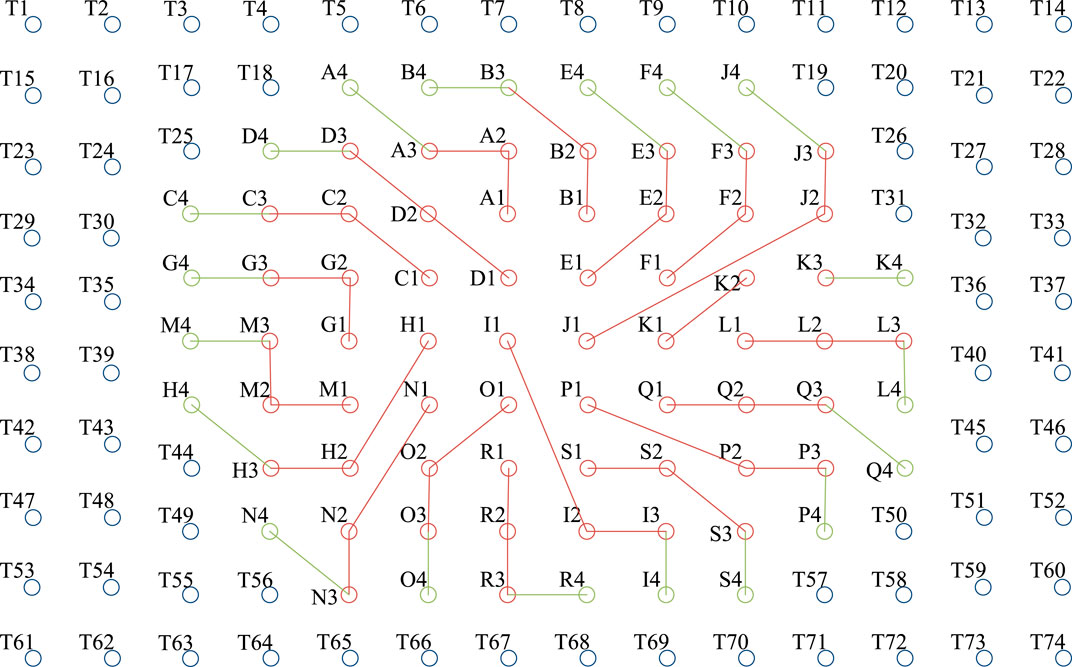
Figure 1. The connection mode for a SAGSHP with buried exchangers using a combination of series and parallel connections.
During heat storage, heat is preferentially stored in the in-series area, and the flow direction of circulating water is from the inside to the outside. When the heat exchange capacity of the in-series area is insufficient, heat is then stored in the surrounding in-parallel area to improve heat storage efficiency. At the end of heat storage, a stepped soil temperature field with high temperature in the middle and low temperature around is formed, which can reduce heat loss. When extracting heat, this model can achieve multiple heat extraction methods. To obtain a higher heat exchange temperature difference, the flow direction of circulating water during heat extraction in the series area is opposite to that during heat storage. In the early stage of heating, when the heat exchange temperature difference is large enough, this part of heat can be used for direct heating to reduce system energy consumption. When the heat exchange temperature difference cannot meet the heating demand, the heat pump is turned on.
2.2 Mathematical model
2.2.1 Assumption for the heat-transfer model
To investigate the effect of different factors on the heat-transfer of BHEs-CSP and find an accurate simplified transfer model, the following assumptions were made.
(1) The vertical single U-pipe BHE is simplified into a heat-exchange tube using the equivalent-diameter method (Gu et al., 1998), and the equivalent diameter is
(2) The effect of underground water and moisture transfer are ignored, and the heat-exchange between the BHEs and the soil is regarded as heat conduction.
(3) The physical properties of the soil are assumed to be uniform and unchanged.
(4) The thermal contact resistance between U-pipe BHEs and soil is negligible.
2.2.2 Development of mathematic models
The mathematic models include governing equation, initial conditions and boundary conditions. Besides, the investigated fluid flow is turbulent, thus, the most commonly used k-ε model was used. These models could be seen as Supplementary Appendix S1.
2.3 Numerical method
2.3.1 Mesh of the model
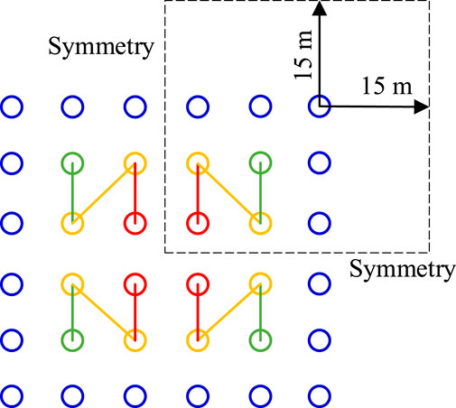
To investigate the effect of the key factors on the heat-transfer performance of BHEs for SAGSHP-CSP, a simplified model of 6 × 6 BHEs was used in this paper. Figure 2 shows the simplified BHEs model. It can be easily found that the model is symmetry, thus, the one-fourth of the model was used, and the corresponding boundaries were set as symmetric. Ref. (Khalajzadeh et al., 2011). showed that the farthest thermal transfer distance for the U-tube was about 10 m. Therefore, the farthest boundary was set to be the boundary at 15 m, where the soil temperature always equaled the initial soil temperature.
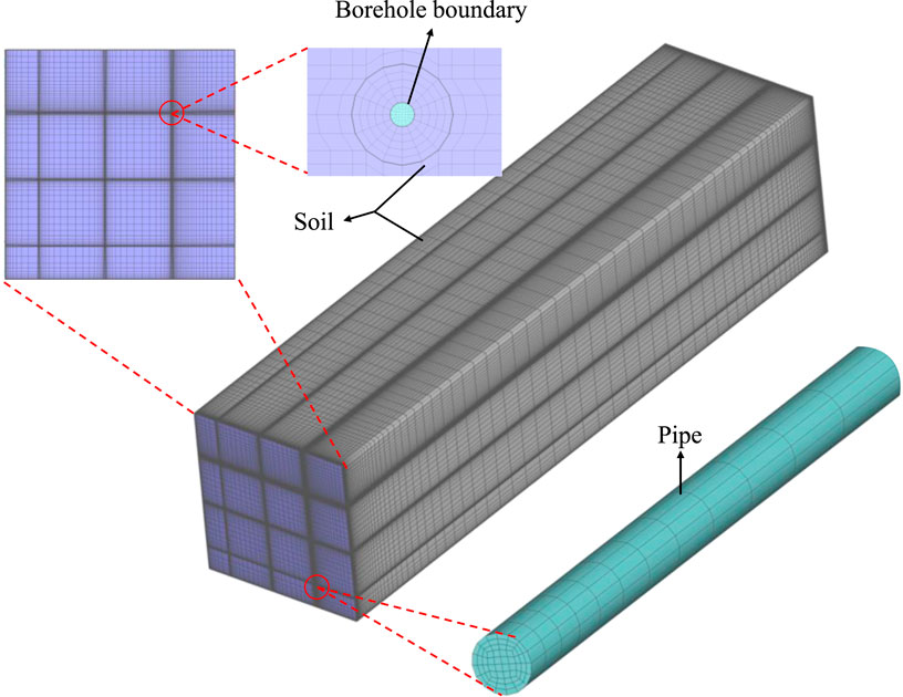
Figure 3 shows the mesh for the BHEs-CSP. The structured grid was developed by ICEM. In the horizontal direction, the grid around the U-tube was denser, while the grid was less dense at the far end. In the vertical direction, the grid was denser at both the inlet and outlet of the U-tube, while the middle of the grid was less dense. In general, the number of grids in the horizontal direction was far denser than that in the vertical direction, which is consistent with the heat-transfer characteristics of the BHEs (Jin et al., 2020).
2.3.2 Settings in the CFD model
The inlet of the U-tube was a velocity boundary (velocity = 0.4 m/s) and the inlet temperature was set to 50°C during the heat-storage period. For the heat-storage period stopped, the velocity was set to 0 m/s. The time for the heat-storage was 8 h per day. The above process could easily be achieved through a user defined function (UDF).
The diameter of the U-tube was De25 mm, the pin space was 80 mm, the buried diameter was 150 mm, and the length of the underground pipe is 75 m. The thermophysical properties of the materials used are shown Table 1.
2.4 Grid independency test
The outlet temperature for different mesh numbers and time step sizes are shown in Table 2. The temperature varied significantly, while the mesh number was below one million. Therefore, the mesh number was set to be 1.03 million. For the time step was above 3,600, the outlet temperature showed large fluctuations. Thus, 3,600 was used as time step in this study.

Table 2. Comparison of water temperature at the outlet of the BHEs for different mesh numbers and time step sizes.
3 Result analysis
The parameters of the BHEs-CSP were optimized using the simplified model in Figure 2. Subsequently, with the optimized parameters, the overall performance of BHEs-CSP was compared with the BHEs-S and BHEs-P.
3.1 Model validation
The validation data were provided by Sun et al., who conducted a field study of a novel SAGSHP system (Sun et al., 2020). The novel system in their study was similar to the SAGSHP-CSP proposed in this paper. Based on the data provided by Sun et al., the same-scale BHEs was established according to Ref. (Sun et al., 2020), using the model described in Section 2. After a 10-day simulation using Fluent, the soil temperature of the W-points in Figure 1 and the outlet temperature were compared–see Figure 4. The initial soil and water temperatures were 12°C and 20°C, respectively, which is consistent with Ref. (Sun et al., 2020).
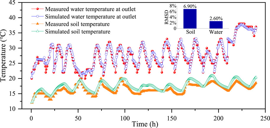
Figure 4. Comparison between the simulated soil and water temperatures and the test values from Ref (Sun et al., 2020)
Overall, good agreement was observed between simulated and test values. The maximum and minimum deviations between simulated and test soil temperatures were −0.96°C and 2.06°C, respectively. The average was 1.07°C. For the water temperature, the deviation between simulated and test values varied from −2.50°C to 2.83°C, with an average of 0.19°C. To evaluate the overall fitness between simulated and test values, the root mean square deviation (RMSD) was used:
The average RMSD for the soil and water temperature, respectively, were 6.90% and 2.60%, which was less than 10%. This indicated that the deviations between simulated and test values were acceptable and the model developed in this paper was accurate.
3.2 Buried spacing and series stages for the in-series zone
The buried spacing and series stages have a high impact on the transfer efficiency of BHEs, the heating capacity of heat pump unit, and the floor area of the BHEs. Moreover, the heat-accumulation effect of the soil temperature field was significantly affected by buried spacing and series stages. Hence, the effect of buried spacing and series stages on the heat-transfer performance for the in-series zone was studied to find the optimal design parameters for SAGSHP-CSP.
3.2.1 Buried spacing
Four kinds of buried spacing were investigated in this study, L = 3.25 m, 4.25 m, 5.25 m, and 6.25 m. After 3 months, the heat capacity for the in-series zone reached to its minimum for every buried spacing. Thus, the running mode changed to heat-extraction. Similarly, the heat-extraction capacity reached a minimum after 1 month.
The heat storage efficiency is the ratio of the actual heat storage capacity of the buried pipe group to the theoretical maximum heat storage capacity, and the corresponding heat extraction efficiency is the ratio of the actual heat extraction capacity of the buried pipe group to the theoretical maximum heat extraction capacity. Figure 5 (a) shows the heat-storage capacity and efficiency for the in-series zone and different buried spacing. Overall, the heat-storage capacity increased with increasing buried spacing. This was because, as buried spacing increased, the soil volume, which was occupied by BHEs increased, and this led to a higher heat capacity. For buried spacing increased from 5.25 m to 6.25 m, the heat capacity increased much faster. This was because, for L = 6.25 m, there was nearly no thermal interference between different U-tubes during the 3-month heat-storage period. The heat-storage efficiency showed a similar regularity with buried spacing but the increase was slower. The heat-storage efficiency was nearly the same for L = 5.25 m and L = 6.25 m.
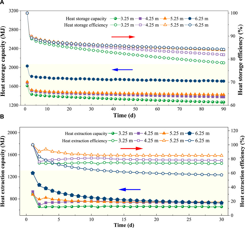
Figure 5. Heat-transfer effect analysis for the in-series zone of BHEs with different buried spacings. (A) Heat storage; (B) Heat extraction.
Figure 5 (b) shows the heat-extraction capacity and efficiency. As the buried spacing increased, the heat-extraction capacity increased. For L = 6.25 m, the heat-extraction increased significantly. At the same time, however, the attenuation also increased. Because the running time was 24 days, the heat-extraction of BHEs with L = 6.25 m was even lower than for L = 5.25 m. Overall, the average heat-extraction efficiency increased first and then decreased. For L = 6.25 m, the average heat-extraction efficiency reached a minimum.
To fully take into account the temperature balance, heat-storage, extraction-capacity and -efficiency, the buried spacing should not be too large or too small. If the buried spacing is too small, the heat accumulation effect is significant after heat-extraction, which does not aid later heat storage. In contrast, if the buried spacing is too large, the attenuation of the heat-extraction is too fast. Thus, the heat-exchange capacity at the later stage (for heat-extraction) is significantly reduced, and the initial investment of the project is too large. To evaluate the overall performance of BHEs, the ratio of heat storage to heat-extraction (RSE) was used. The closer RSE is to 1, the better is the thermal balance obtained in the soil following a full heat-storage and -extraction circle. Table 3 shows the RSE values for the in-series BHEs with different buried spacings. It can be found that the RSE values increased first and then decreased with increasing buried spacing. They reached a maximum for L = 5.25 m. Therefore, 5.25 m is the recommended buried spacing for the in-series zone of a BHEs-CSP.

Table 3. The ratio of heat storage to heat-extraction for in-series BHEs and different buried spacings.
3.2.2 Series stages
Two, three, four, and five series-stages were investigated in this study. The second-level series connection consists of two BHEs connected in series, the third-level series connection consists of three BHEs connected in series, and similarly, the fourth-level and fifth-level series connections consist of four and five BHEs connected in series, respectively.
Figure 6A shows the heat-storage capacity and efficiency for the in-series zone of BHEs with different series stages. The heat-storage capacity increased with increasing series stages. However, when the number of series stages exceeded three, the heat-storage capacity increased slightly. This was because, as the series stage increased, the circulation path for water in the U-tube was longer, which increased the heat exchange. Concurrently, the temperature difference between water and soil at the end of in-series U-tube decreased. As a result, the heat-transfer efficiency decreased. Therefore, as the number of series stages increased, the heat-storage efficiency also increased slightly.
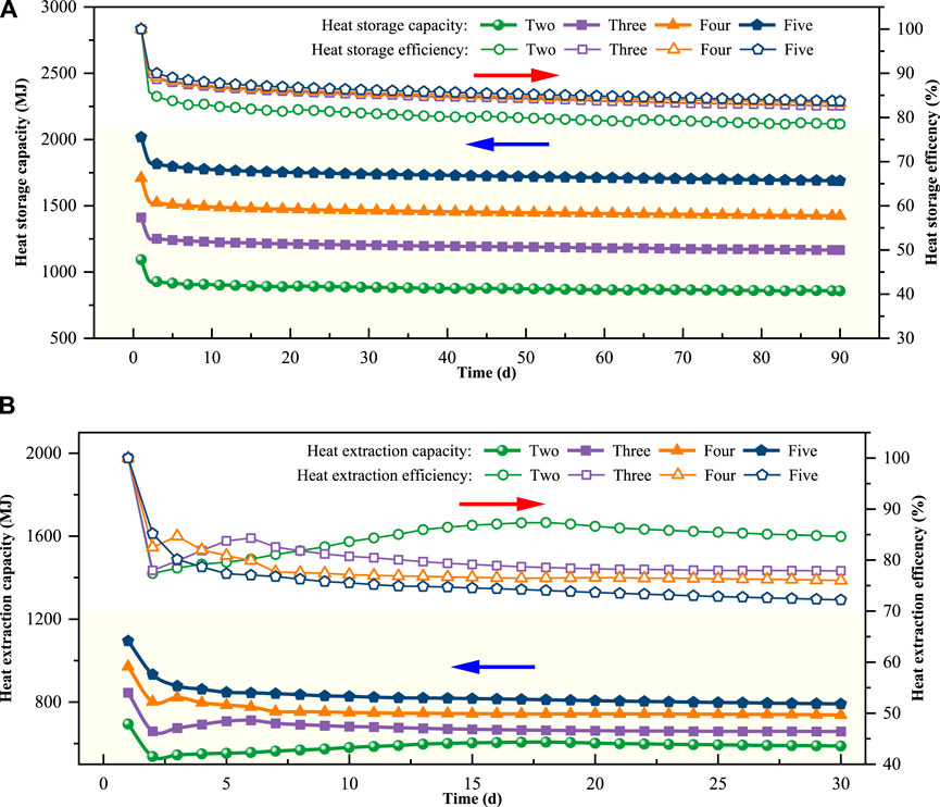
Figure 6. Heat-transfer-effect analysis for the in-series zone of BHEs with different series stages. (A) Heat storage; (B) Heat extraction.
Figure 6A shows the corresponding heat-extraction capacity and -efficiency. As the series stages increased, the heat-extraction capacity increased. However, when the series stage number was five, the heat-extraction capacity attenuated substantially. The heat-extraction efficiency decreased with increasing series stages. This was because, as the series stages increased, the temperature difference between water and soil at the end of the in-series U-tube decreased, which decreased the heat-extraction.
Table 4 shows the RSE for in-series zone of BHEs with different stages. As the series stages increased, the RSE decreased and the degree of thermally unbalanced soil increased. However, considering the heat-storage capacity, more series stages should be used, while fewer series stages are recommended for thermal balancing of the soil. Therefore, four series stages are recommended.

Table 4. The ratio of heat-storage to heat-extraction for in-series BHEs with different numbers of series stages.
3.3 Buried spacing in the in-parallel zone
After the optimal configuration for the in-series zone had been determined, the remaining zone in Figure 2 was set to be the in-parallel zone. For the in-parallel zone, the only design parameter, which needed to be optimized, was buried spacing. Similarly, four different buried spacings, L = 3.25 m, 4.25 m, 5.25 m, and 6.25 m, were investigated. The running times for heat storage and heat-extraction were set to 15 days.
Figure 7A illustrates the trend of the heat-storage capacity and the heat-storage efficiency for the in-parallel zone with different buried spacings. The heat-storage capacity increased with increasing buried spacing. For L = 6.25 m, the heat capacity reached a maximum. This is because when the pipe spacing L = 6.25 m, there is almost no thermal interference between different BHEs during 3 months of heat storage, resulting in a significant increase in heat storage capacity. The heat storage efficiency also increases with increasing pipe spacing, but the increase rate slows down. There is little difference in heat storage efficiency between pipe spacing L = 5.25 m and L = 6.25 m. This is because as the pipe spacing increases, the thermal interference between different BHEs decreases. Therefore, although the heat storage efficiency improves with operating time, the increase is not significant.
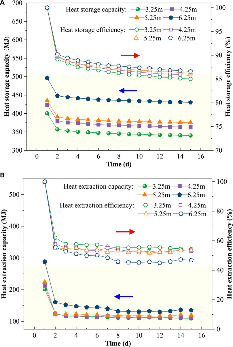
Figure 7. Analysis of the heat-transfer effect for the in-parallel zone of BHEs with different buried spacings. (A) Heat storage; (B) Heat extraction.
Figure 7B illustrates the trend of the heat-extraction capacity and efficiency for the in-parallel zone with different buried spacings. The heat-extraction-capacity and -efficiency decreased with increasing buried spacing. As the pipe spacing increases, the heat extraction capacity of the BHEs also increases, and the distribution pattern of heat extraction temperature difference is consistent with that of heat extraction capacity. When the pipe spacing L = 6.25 m, the heat extraction capacity increases significantly, but at the same time, its attenuation rate also increases. Starting from the operating time of d = 24 days, the heat extraction capacity of the BHEs at L = 6.25 m is already significantly lower than that at L = 5.25 m. As can be seen from Figure 7A, the heat storage capacity at L = 6.25 m increases significantly. Because the BHEs has a large heat storage capacity, the heat extraction capacity of the buried pipes also increases accordingly. However, the larger the pipe spacing, the greater the amount of heat diffusion in the soil within the same time, so the attenuation rate of heat extraction capacity is significant. The heat extraction efficiency shows a trend of first increasing and then decreasing with increasing pipe spacing, and the heat extraction efficiency is the worst when the spacing L = 6.25 m.
Table 5 shows the RSE for heat-extraction for the in-parallel zone of the BHEs. Overall, the RSE decreased with increasing buried spacing. For L = 6.25 m, the RSE was lowest. However, considering the heat capacity, wider buried spacing should be used. Therefore, when taking the heat balance of soil and heat-storage capacity into account, 5.25 m are recommended to be the optimal buried spacing for the in-parallel zone of BHEs.

Table 5. The ratio of heat-storage to heat-extraction for the in-series BHEs and different buried spacings.
3.4 Heat-extraction methods
According to the least heat-loss principle, the heat-storage methods of the BHEs of SAGSHP-CSP could be determined. The heat-extraction, however, was much more complex, which would significantly affect the overall heat-transfer efficiency of the BHEs. Therefore, four heat-extraction methods are proposed in this paper–see as follows:
(1) Mode 1: Take heat from the series area first, and then take heat from the parallel area when the heat exchange capacity of the series area is insufficient.
(2) Mode 2: The priority is to take heat from the series area, and when the heat exchange capacity of the series area is insufficient, take heat from two sections at the same time.
(3) Mode 3: Take heat from the parallel area first, and then take heat from the series area when the heat exchange capacity of the parallel area is insufficient.
(4) Mode 4: The priority is to take heat from the parallel area. When the heat exchange capacity of the parallel area is insufficient, the heat is taken from two areas at the same time.
Based on the optimal buried spacing and series stages, an optimal layout for the BHEs-CSP model was established. The water temperature during heat-extraction was set to 7°C. Note that, for the simulation, the computing effort was too high when the temperature differences fell below 5°C in the CFD. Because the purpose was to compare different heat-extraction methods, similar results would be obtained if the heat-extraction was similar. Therefore, the heat-extraction was set to 90 days. Furthermore, the heat-extraction period was 60 days for the in-series zone and 30 days for the in-parallel zone.
Through UDF, the heat-transfer difference, soil-temperature distribution, and RSE were compared for different heat-extraction methods. Figure 8 shows the heat-transfer temperature differences between water at the inlet and outlet for different heat-extraction methods. For S1, during the first 30 days, the variation in temperature difference was between 6.3°C and 9.3°C with average values of 6.7°C. For the later 60 days, during which the heat was extracted from the in-series zone, the temperature difference varied from 7.6°C to 8.4°C, and the average temperature difference was 7.8°C. In terms of S2, the temperature differences changed similarly to that of S1. From Figure 8, it can also be found that for S1 and S2, with increasing running time, the temperature increased gradually. This is the case because heat was transferred from the in-series zone to the in-parallel zone, which caused the soil temperature in the in-parallel zone to increase.
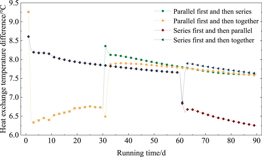
Figure 8. Heat-transfer temperature difference between BHEs and soil for different heat-extraction methods.
For S3, even though there was a high temperature difference with an average of 7.9°C during the first 2 months, there was a low temperature difference (average 6.5°C) during the last month. Moreover, the attenuation occurred fast. As for S4, the temperature differences during the full heat-extraction remained high. The average temperature-difference was 7.8°C. There were sudden changes on the 30th or 60th day, which was caused by the boundary change. This represents a reasonable outcome for the numerical simulation. Overall, considering the temperature difference, the heat-extraction method of S4 is recommended.
Figure 9 shows the soil temperature distribution at a depth of 35 m for different heat-extraction methods. It can be easily found that the soil temperature, using methods S4, was always lower than for other methods, which was better for heat-storage during the next period.
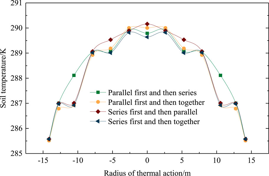
Figure 9. Distribution of the soil temperature field at a depth of 35 m for different heat-extraction methods.
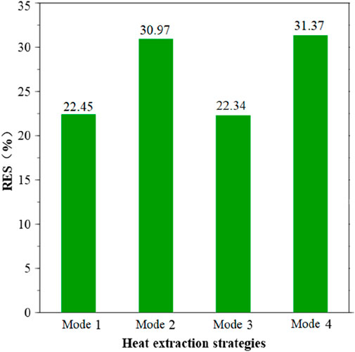
Figure 10 shows the RSE for different heat-extraction methods. For S1 and S3, the RSE was much lower than S2 and S4. The RSE reached to a maximum for S4 with a value of 31.37%. Therefore, considering the heat-transfer temperature differences, soil temperature distribution, and RSE, method S4 is highly recommended.
3.5 Comparison between BHEs-CSP with BHEs-S and BHEs-P
To compare the overall performances of BHEs-CSP, -S and -P, the same-scale BHEs with the same boundary conditions were used according to Ref. (Sun et al., 2020). using the model of Section 2. A comparison of heat-transfer temperature and -efficiency, between BHEs-CSP with optimal configuration and conventional BHEs-S or BHEs-P, is shown in Figure 11.
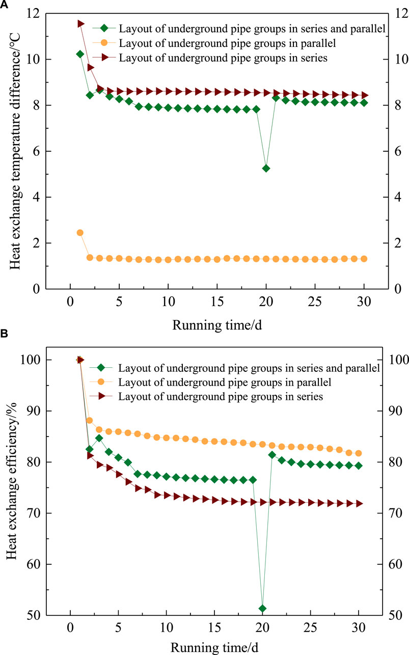
Figure 11. Comparison of heat-transfer temperature differences and -efficiency for BHEs with different connection types. (A) Heat-transfer temperature differences; (B) Heat-transfer efficiency
Using Figure 11A, it can be found that the average temperature differences of BHEs-CSP and -S, between water at inlet and outlet, were 6.70°C and 7.35°C higher, respectively, than for BHEs-P. This benefited the heat pump. Similarly, according to Figure 11B, the heat-transfer efficiency of BHEs-P was highest (average 84.63%), while that of BHEs-S was lowest (average 74.53%). The average transfer-efficiency of BHEs-CSP was improved by 4.1% compared to BHEs-S. After 20 days, the temperature difference in the in-series zone of the BHEs-CSP was below 5°C, and the heat-transfer performance reached the same value as for BHEs-P. Consequently, the heat started to be extracted from both in-series and in-parallel zones. The speed boundary of the in-parallel zone jumped from 0 m/s to 0.56 m/s, which caused a sudden change in the simulation results.
Overall, the BHEs-CSP could not only reach a higher heat-transfer efficiency but also improve the heat-transfer temperature differences. It can improve both the problems associated with the low heat-transfer efficiency of BHEs-S or the small heat-transfer temperature difference of the BHEs-P.
4 Discussion
The optimal area (ARSP) and heat-storage ratio (HRSP) of the in-series zone to the in-parallel zone was significant to the SAGSHP-CSP system. Therefore, to obtain the optimal values, using the optimal configuration of BHEs-CSP, the SAGSHP-CSP was established using TRNSYS-18. Subsequently, SAGSHP-CSP was compared with SAGSHP-S and SAGSHP-P. A detailed system description of SAGSHP-CSP, -S and -P can be found in Refs. (Zhang et al., 2016; Qi et al., 2019; Sun et al., 2020).
4.1 Simulation-model development
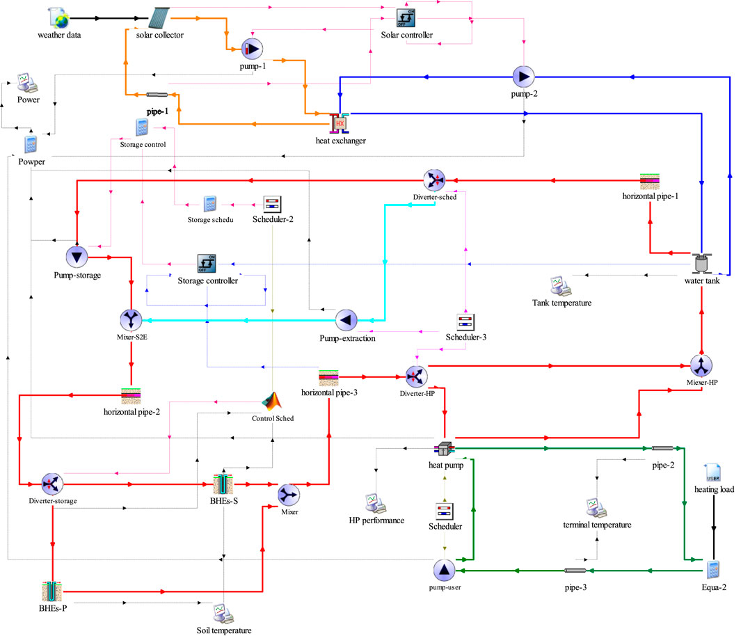
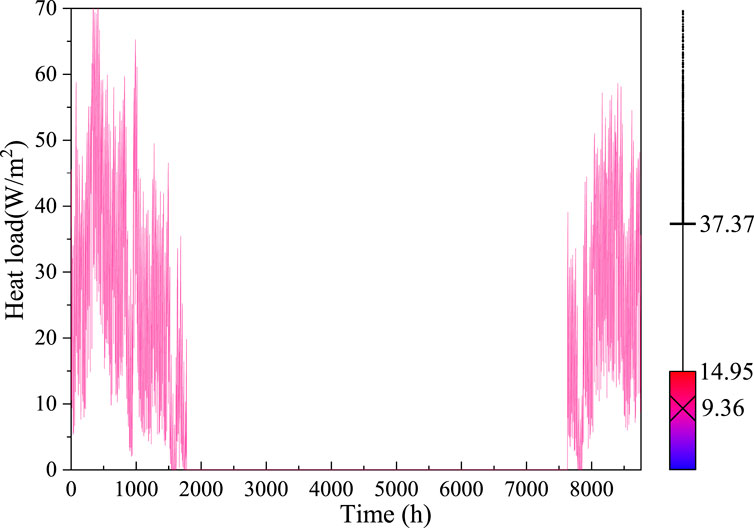
The simulation models for the SAGSHP-CSP, -S and -P systems were developed using TRNSYS 18.0–see Figure 12. During the simulation, the TRNSYS models for the in-series and the in-parallel zone were established separately. By changing the number of buried pipes, connection types and solar collector areas, the overall performance of the SAGSHP-CSP, -S and -P systems were studied. The main components and the corresponding parameters used in the TRNSYS simulation could be referred to Supplementary Table S1 in Supplementary Material. Figure 13 shows the heating load in the building during a year.
4.2 Model validation
The validation data were also provided by Sun et al. (2020). In their project, the ARSP was 1:1 and HRSP was 3:2. The heating time was from November 15th to March 15th of the next year. The operation data of the second year of the system were used as validation data. The initial soil temperature for the in-series zone was 37°C, while that for the in-parallel zone was 20°C. The total heating area was 22,342 m2; the maximum heating load was 554 kW; the design supply and return heating water temperatures were 50°C and 40°C, respectively. More detailed information can be found in Ref. (Sun et al., 2020).
The capacity, scale and initial conditions of the TRNSYS model were set to the same values as in Ref. (Sun et al., 2020). After a full heat-storage and extraction period, the soil temperature, average temperature of heat-storage tank, and return-water temperature during the heating period are shown in Figure 14.
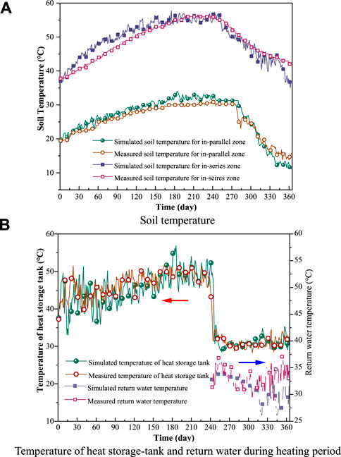
Figure 14. Comparison between simulated and measured soil temperature, heat-storage tank temperature, and return-water temperature. (A) Soil temperature; (B) return-water temperature.
Overall, the RMSD between the simulated soil temperature and measured values for the in-series zone was 5.5%, while the value for the in-parallel zone was 8.5%. The RMSD between simulated and measured average temperature of the heat-storage tank was 9.0%; the RMSD between simulated return-water temperature during the heating period and the measured values was 6.1%. All RMSD values were below 10%, which indicates that the models in this study are sufficiently accurate.
4.3 Optimal area and heat-storage ratio of the in-series to the in-parallel zone
The operating times of the SAGSHP-CSP system with heat-storage and heat-extraction conditions are shown in Table 6.
To determine the optimal ARSP and HRSP values, different cases were investigated–see Table 7. When the ARSP was 5:0 and HRSP was 5:0, the conventional SAGSHP-S system was used. When the ARSP was 0:5 and HRSP was 0:5, the conventional SAGSHP-P system was used.
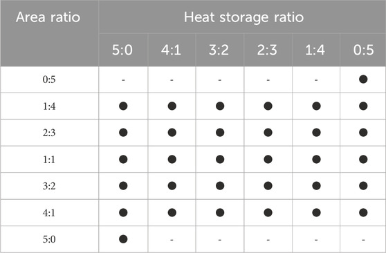
Table 7. The studied cases for area and heat-storage ratios of the in-series to the in-parallel zones.
The initial soil temperature was set to 14.8°C. Seventeen simulated cases were conducted for a full heat-storage and -extraction period. During the heat-storage period, provided the average soil temperature was above 50°C, the hot water heated by the BHEs could be transferred to the end-users directly. Otherwise, the heat pump was opened. Figure 15 shows the variation of soil temperature for different ARSP and HRSP values.
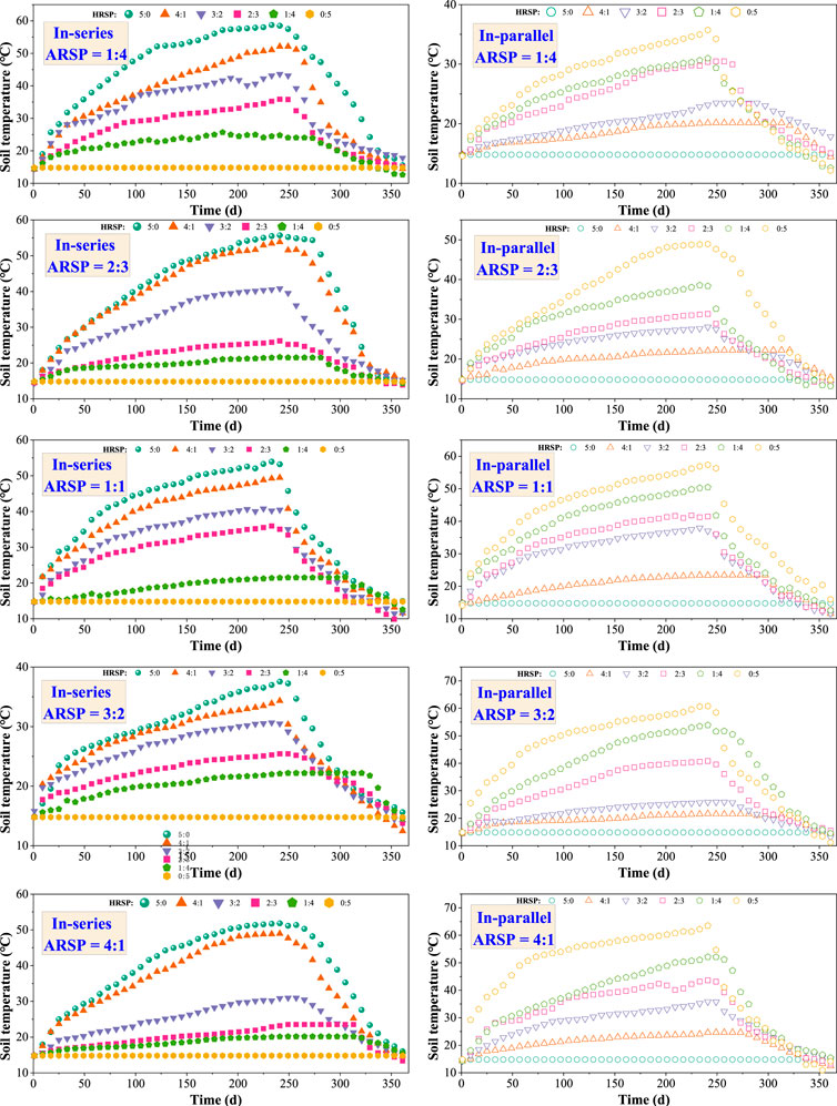
Figure 15. The variations of soil temperature for the in-series and the in-parallel zones for different ARSP and HRSP conditions.
For the in-series zone, when the ARSP values were 1:4 and 2:3, and the HRSP was above 4:1, or when the ARSP was 1:1 and the HRSP was 5:0, the soil temperature would be above 50°C. In addition, the heat pump could not be opened at the beginning of the heating period. For the in-parallel zone, when ARSP was 1:1, 1:3, and 4:1, and HRSP was 0:5, the in-parallel zone was able to meet the direct heating requirements.
Overall, for a smaller ARSP and higher HRSP, the soil temperature could reach higher values after the heating storage period. However, the decreased rate of the soil temperature at the beginning of heat-extraction period increased faster. For ARSP = 1:4 and HRSP = 3:2, the soil temperature during the operating period of the heat pump decreased slowly.
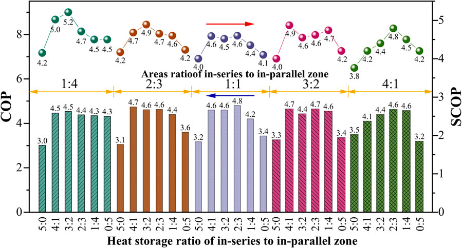
For the same relative scale of solar collector, water storage tank, BHEs, and other components, the coefficient of performance (COP) for the heat pump and electricity of each component of the SAGSHP-P, SAGSHP-S, and SAGSHP-CSP could be simulated using TRNSYS. Thus, the system COP (SCOP) could be calculated. For the SAGSHP-S system, during the running period, the COP of the heat pump was 3.8, and the SCOP was 4.4; in terms of SAGSHP-P, the corresponding COP and SCOP were 4.1 and 4.6, respectively. Both COP and SCOP of SAGSHP-CSP are shown in Figure 16.
In extreme cases (all heat was stored in the in-series zone and the heat-storage ratio of in-series to the in-parallel zone was 5:0), the COPs of SAGSHP-CSP for different area ratios were 3.0, 3.1, 3.2, 3.3, and 3.5. The corresponding SCOP values were 4.2, 4.2, 4.0, 4.0, and 3.8. The COP and SCOP were always below the values for SAGSHP-S and -P. The area and heat-storage ratios were closer to the conventional SAGSHP-S or -P system, while the COP and SCOP of SAGSHP-CSP were closer to those of them. Therefore, if the area of BHEs was reduced, without considering that the system can meet the requirements of direct supply in the early stage of heating and reduce the start-up time of the heat pump, the soil temperature drops too fast in the later stage. In addition, the COP of the heat pump and SCOP of the SAGSHP-CSP system are reduced.
When the heat-storage ratio was the same as the area ratio of the in-series zone to the in-parallel zone, both COP and SCOP were not the highest. For example, for the area and heat-storage ratio of 1:4, the COP and SCOP were 4.3 and 4.5, respectively, which was 0.2 and 0.7 less then when the area ratio was 1:4 and heat-storage ratio was 3:2. Therefore, the heat-storage ratio is not recommended to be determined by the area ratio.
The highest COP and SCOP were observed in the case that the area ratio was 1:4 and the heat-storage ratio was 3:2. For this case, the COP and SCOP with the values 4.5 and 5.2, respectively, represented the best overall performances.
Overall, the optimal area and heat-storage ratios of the in-series and the in-parallel zones were 1:4 and 3:2. Compared to the SAGSHP-P system, the COP and SCOP improved by 9.8% and 13.0%, respectively, while the corresponding values improved by 18.4% and 18.2%, respectively, compared to the SAGSHP-S system.
5 Conclusion
A novel SAGSHP-CSP system was proposed in this paper. To determine the optimal buried spacing, series stages, and heat-extraction methods, a numerical model was established. The model was validated using an existing real-life study. Furthermore, to determine the optimal area and heat-storage ratio of the in-series to the in-parallel zone, a TRNSYS model for the SAGSHP-CSP system was developed. The following conclusions were made.
(1) Based on minimized heat loss, the heat-storage method included that the heat was first stored in the in-series zone, and when the heat capacity was insufficient, the heat was stored in the in-parallel zone. Using a simulation of different heat-extraction methods, the recommended heat-extraction method should be that the heat is first extracted from in-series zone, and only when the heat capacity is insufficient, the heat is extracted from both in-series and in-parallel zones.
(2) Comprehensively considering the heat-storage- and heat-extraction-capacity and -efficiency, the optimal buried spacing for the in-series and the in-parallel zone is recommended to be 5.25 m. The number of series stages for the in-series zone is recommended to be four. Using optimal design parameters, the average temperature difference of the BHEs-CSP improved by 6.70°C compared to BHEs-P, and the heat-transfer efficiency of BHEs-CSP improved by 4.1% compared to BHEs-S.
(3) The area and heat-storage ratios of the in-series to the in-parallel zone for SAGSHP-CSP were 1:4 and 3:2, respectively. For this case, the COP and SCOP improved by 9.8% and 13.0%, respectively, compared to the SAGSHP-P system. The corresponding values are improvements by 18.4% and 18.2%, respectively, compared to the SAGSHP-S system.
In conclusion, the novel structure proposed in this paper possesses advantages such as simplicity, high efficiency, and ease of implementation, offering a new approach for engineering practice. However, it is worth noting that it is not advisable to allocate heat storage capacity in the series and parallel zones solely based on the zone area. If blindly reduce the area of the buried pipe group and increase the heat storage ratio, the SAGSHP system can initially meet direct supply conditions during the heating season, reducing the heat pump’s operating time. Nevertheless, in the later stages, the soil temperature may drop rapidly, resulting in a decrease in both the heat pump’s COP and the system’s SCOP compared to traditional systems.
Data availability statement
The original contributions presented in the study are included in the article/Supplementary Material, further inquiries can be directed to the corresponding author.
Author contributions
CW: Writing–original draft, Writing–review and editing. MS: Writing–original draft, Writing–review and editing. LJ: Writing–original draft, Writing–review and editing. QF: Writing–original draft. LZ: Writing–original draft.
Funding
The author(s) declare that financial support was received for the research, authorship, and/or publication of this article. This paper was supported by the Scienihc and Technological Research Fund of China Academy of Building Research (Project Nos. 20220109330730015).
Acknowledgments
This paper was supported by the Scientific and Technological Research Fund of China Academy of Building Research (Project Nos. 20220109330730015). The model validation data used in this paper was kindly provided by Tingting Sun.
Conflict of interest
Author LJ was employed byShanghai Municipal Engineering Design Institute (Group) Co., Ltd.
The remaining authors declare that the research was conducted in the absence of any commercial or financial relationships that could be construed as a potential conflict of interest.
Publisher’s note
All claims expressed in this article are solely those of the authors and do not necessarily represent those of their affiliated organizations, or those of the publisher, the editors and the reviewers. Any product that may be evaluated in this article, or claim that may be made by its manufacturer, is not guaranteed or endorsed by the publisher.
Supplementary material
The Supplementary Material for this article can be found online at: https://www.frontiersin.org/articles/10.3389/fenrg.2024.1430707/full#supplementary-material
References
Aranzabal, N., Martos, J., Hagen, S., Blum, P., and Soret, J. (2019). Temperature measurements along a vertical borehole heat exchanger: a method comparison. Renew. Energy 143, 1247–1258. doi:10.1016/j.renene.2019.05.092
Bakirci, K. (2010). Evaluation of the performance of a ground-source heat-pump system with series GHE (ground heat exchanger) in the cold climate region. Energy 35, 3088–3096. doi:10.1016/j.energy.2010.03.054
Chen, S., Cai, W., Witte, F., Wang, X., Wang, F., Kolditz, O., et al. (2020a). Long-term thermal imbalance in large borehole heat exchangers array - a numerical study based on the Leicester project. Energy Build. 231, 110518. doi:10.1016/j.enbuild.2020.110518
Chen, S., Witte, F., Kolditz, O., and Shao, H. (2020b). Shifted thermal extraction rates in large Borehole Heat Exchanger array – a numerical experiment. Appl. Therm. Eng. 167, 114750. doi:10.1016/j.applthermaleng.2019.114750
Deng, Y., Liu, Y. C., Zhang, Y., Zeng, R., Zheng, Z. M., Yao, Y., et al. (2022). Optimization and performance analysis of CCHP-GSHP-SE system under different start factors. Energy Convers. Manag. 266, 115827. doi:10.1016/j.enconman.2022.115827
Emmi, G., Zarrella, A., De Carli, M., and Galgaro, A. (2015). An analysis of solar assisted ground source heat pumps in cold climates. Energy Convers. Manag. 106, 660–675. doi:10.1016/j.enconman.2015.10.016
Florides, G. A., Christodoulides, P., and Pouloupatis, P. (2013). Single and double U-tube ground heat exchangers in multiple-layer substrates. Appl. Energy 102, 364–373. doi:10.1016/j.apenergy.2012.07.035
Georgiev, A., Popov, R., and Toshkov, E. (2020). Investigation of a hybrid system with ground source heat pump and solar collectors: charging of thermal storages and space heating. Renew. Energy 147, 2774–2790. doi:10.1016/j.renene.2018.12.087
Gu, Y., Dennis, L., and O'Neal, A. (1998). Development of an equivalent diameter expression for vertical U-tubes used in ground-coupled heat pumps. ASHRAE Trans. 104, 347–355.
Hamid, N., Ghasempour, R., and Noorollahi, Y. (2016). The effect of employing nanofluid on reducing the bore length of a vertical ground-source heat pump. Energy Convers. Manag. 123, 581–591. doi:10.1016/j.enconman.2016.06.079
Han, J. Y., Cui, M. H., Chen, J. Y., and Lv, W. J. (2021). Analysis of thermal performance and economy of ground source heat pump system: a case study of the large building. Geothermics 89, 101929. doi:10.1016/j.geothermics.2020.101929
Hesaraki, A., Holmberg, S., and Haghighat, F. (2015). Seasonal thermal energy storage with heat pumps and low temperatures in building projects—a comparative review. Renew. Sustain. Energy Rev. 43, 1199–1213. doi:10.1016/j.rser.2014.12.002
Hou, Z., Hu, Y. Q., Liu, X. J., Wang, J. H., Yang, M., and Fan, J. (2023). Numerical investigation on free cooling performance of ground-source heat pump in a solar greenhouse. Therm. Sci. 27, 4719–4732. doi:10.2298/tsci221203161h
Houman Razavi, S., Ahmadi, R., and Zahedi, A. (2018). Modeling, simulation and dynamic control of solar assisted ground source heat pump to provide heating load and DHW. Appl. Therm. Eng. 129, 127–144. doi:10.1016/j.applthermaleng.2017.10.003
Hu, J. (2017). An improved analytical model for vertical borehole ground heat exchanger with multiple-layer substrates and groundwater flow. Appl. Energy 202, 537–549. doi:10.1016/j.apenergy.2017.05.152
Huang, J., Fan, J., and Simon, F. (2020). Demonstration and optimization of a solar district heating system with ground source heat pumps. Sol. Energy 202, 171–189. doi:10.1016/j.solener.2020.03.097
Jin, G., Li, Z., Guo, S., Wu, X., Wu, W., and Zhang, K. (2020). Thermal performance analysis of multiple borehole heat exchangers in multilayer geotechnical media. Energy 209, 118236. doi:10.1016/j.energy.2020.118236
Jonas, D., Frey, G., and Theis, D. (2017). Simulation and performance analysis of combined parallel solar thermal and ground or air source heat pump systems. Sol. Energy 150, 500–511. doi:10.1016/j.solener.2017.04.070
Jun, Z., Yang, L., and Wang, J. (2016). A review on heat transfer enhancement of borehole heat exchanger. Energy Procedia 104, 413–418. doi:10.1016/j.egypro.2016.12.070
Kapicioglu, A., and Kale, C. (2023). Techno-economic analysis of ground source heat pump powered by hybrid photovoltaic-wind-diesel systems in a temperate climate region. J. Therm. ANALYSIS Calorim. 148, 8443–8457. doi:10.1007/s10973-023-12071-x
Keshavarzzadeh, A. H., Maleki Zanjani, A., Gharali, K., and Dusseault, M. B. (2020). Multi-objective evolutionary-based optimization of a ground source heat exchanger geometry using various optimization techniques. Geothermics 86, 101861. doi:10.1016/j.geothermics.2020.101861
Khalajzadeh, V., Heidarinejad, G., and Srebric, J. (2011). Parameters optimization of a vertical ground heat exchanger based on response surface methodology. Energy Build. 43, 1288–1294. doi:10.1016/j.enbuild.2011.01.007
Kumar, S., and Murugesan, K. (2020). Optimization of geothermal interaction of a double U-tube borehole heat exchanger for space heating and cooling applications using Taguchi method and utility concept. Geothermics 83, 101723. doi:10.1016/j.geothermics.2019.101723
Lee, M., Ham, S. H., Lee, S., Kim, J., and Kim, Y. (2023). Multi-objective optimization of solar-assisted ground-source heat pumps for minimizing life-cycle cost and climate performance in heating-dominated regions. Energy 270, 126868. doi:10.1016/j.energy.2023.126868
Li, H. Y., Bi, Y. H., Wang, H. Y., and Sun, R. R. (2023). Multi-objective optimization of an absorption solar-ground source heat pump considering the environmental and economic performance. Int. J. green energy 20, 1177–1190. doi:10.1080/15435075.2022.2155824
Luo, J., Rohn, J., Xiang, W., Bertermann, D., and Blum, P. (2016). A review of ground investigations for ground source heat pump (GSHP) systems. Energy Build. 117, 160–175. doi:10.1016/j.enbuild.2016.02.038
Magraner, T., Montero, Á., Cazorla-Marín, A., Montagud-Montalvá, C., and Martos, J. (2020). Thermal response test analysis for U-pipe vertical borehole heat exchangers under groundwater flow conditions. Renew. Energy 165, 391–404. doi:10.1016/j.renene.2020.11.029
Marcotte, D., and Pasquier, P. (2014). Unit-response function for ground heat exchanger with parallel, series or mixed borehole arrangement. Renew. Energy 68, 14–24. doi:10.1016/j.renene.2014.01.023
Naicker, S. S., and Rees, S. J. (2020). Long-term high frequency monitoring of a large borehole heat exchanger array. Renew. Energy 145, 1528–1542. doi:10.1016/j.renene.2019.07.008
Naranjo-Mendoza, C., Oyinlola, M. A., Wright, A. J., and Greenough, R. M. (2019). Experimental study of a domestic solar-assisted ground source heat pump with seasonal underground thermal energy storage through shallow boreholes. Appl. Therm. Eng. 162, 114218. doi:10.1016/j.applthermaleng.2019.114218
Niemann, P., and Schmitz, G. (2019). Experimental investigation of a ground-coupled air conditioning system with desiccant assisted enthalpy recovery during winter mode. Appl. Therm. Eng. 160, 114017. doi:10.1016/j.applthermaleng.2019.114017
Noorollahi, Y., Shabbir, M. S., Siddiqi, A. F., Ilyashenko, L. K., and Ahmadi, E. (2019). Review of two decade geothermal energy development in Iran, benefits, challenges, and future policy. Geothermics 77, 257–266. doi:10.1016/j.geothermics.2018.10.004
Nordgård-Hansen, E., Kishor, N., Midttomme, K., Risinggård, V. K., and Kocbach, J. (2022). Case study on optimal design and operation of detached house energy system: solar, battery, and ground source heat pump. Appl. Energy 308, 118370. doi:10.1016/j.apenergy.2021.118370
Nouri, G., Noorollahi, Y., and Yousefi, H. (2019a). Solar assisted ground source heat pump systems – a review. Appl. Therm. Eng. 163, 114351. doi:10.1016/j.applthermaleng.2019.114351
Nouri, G., Noorollahi, Y., and Yousefi, H. (2019b). Designing and optimization of solar assisted ground source heat pump system to supply heating, cooling and hot water demands. Geothermics 82, 212–231. doi:10.1016/j.geothermics.2019.06.011
Park, H., Lee, J. S., Kim, W., and Kim, Y. (2012). Performance optimization of a hybrid ground source heat pump with the parallel configuration of a ground heat exchanger and a supplemental heat rejecter in the cooling mode. Int. J. Refrig. 35, 1537–1546. doi:10.1016/j.ijrefrig.2012.05.002
Park, H., Lee, J. S., Kim, W., and Kim, Y. (2013). The cooling seasonal performance factor of a hybrid ground-source heat pump with parallel and serial configurations. Appl. Energy 102, 877–884. doi:10.1016/j.apenergy.2012.09.035
Penrod, E. B., and Prasanna, K. V. (1962). Design of a flat-plate collector for a solar earth heat pump. Sol. Energy 6, 9–22. doi:10.1016/0038-092x(62)90093-2
Penrod, E. B., and Prasanna, K. V. (1965). Analysis of a proposed solar-earth heat pump. Soil Sci. 100, 75. doi:10.1097/00010694-196507000-00031
Qi, D., Pu, L., Ma, Z., Xia, L., and Li, Y. (2019). Effects of ground heat exchangers with different connection configurations on the heating performance of GSHP systems. Geothermics 80, 20–30. doi:10.1016/j.geothermics.2019.02.002
Reda, F. (2015). Long term performance of different SAGSHP solutions for residential energy supply in Finland. Appl. Energy 144, 31–50. doi:10.1016/j.apenergy.2015.01.059
Saeidi, R., Noorollahi, Y., and Esfahanian, V. (2018). Numerical simulation of a novel spiral type ground heat exchanger for enhancing heat transfer performance of geothermal heat pump. Energy Convers. Manag. 168, 296–307. doi:10.1016/j.enconman.2018.05.015
Sankelo, P., Ahmed, K., Mikola, A., and Kurnitski, J. (2022). Renovation results of Finnish single-family renovation subsidies: oil boiler replacement with heat pumps. Energies 15, 7620. doi:10.3390/en15207620
Sarbu, I., and Sebarchievici, C. (2014). General review of ground-source heat pump systems for heating and cooling of buildings. Energy Build. 70, 441–454. doi:10.1016/j.enbuild.2013.11.068
Sun, T., Yang, L., Jin, L., Luo, Z., Zhang, Y., Liu, Y., et al. (2020). A novel solar-assisted ground-source heat pump (SAGSHP) with seasonal heat-storage and heat cascade utilization: field test and performance analysis. Sol. Energy 201, 362–372. doi:10.1016/j.solener.2020.03.030
Wang, X., Li, T., Yu, Y., Liu, X., Liu, Y., Wang, S., et al. (2024). Energy saving and economic analysis of a novel PV/T coupled multi-source heat pump heating system with phase change storage: a case study in cold zone in China. Energy Convers. Manag. 312, 118574. doi:10.1016/j.enconman.2024.118574
You, T., Li, X., Cao, S., and Yang, H. (2018). Soil thermal imbalance of ground source heat pump systems with spiral-coil energy pile groups under seepage conditions and various influential factors. Energy Convers. Manag. 178, 123–136. doi:10.1016/j.enconman.2018.10.027
Zeng, H., Diao, N., and Fang, Z. (2003). Heat transfer analysis of boreholes in vertical ground heat exchangers. Int. J. Heat Mass Transf. 46, 4467–4481. doi:10.1016/s0017-9310(03)00270-9
Zhang, C., Hu, S., Liu, Y., and Wang, Q. (2016). Optimal design of borehole heat exchangers based on hourly load simulation. Energy 116, 1180–1190. doi:10.1016/j.energy.2016.10.045
Keywords: borehole heat exchangers, solar-assisted ground-source heat-pump, combined series and parallel connection, design parameter optimization, heat transfer
Citation: Wu C, Song M, Jin L, Fu Q and Zhu L (2024) Heat transfer and system performance of a novel solar ground-source heat-pump system with borehole heat exchangers using a combined parallel and series connection. Front. Energy Res. 12:1430707. doi: 10.3389/fenrg.2024.1430707
Received: 10 May 2024; Accepted: 21 June 2024;
Published: 26 July 2024.
Edited by:
Fangtong Liu, Jinan University, ChinaReviewed by:
Gejirifu De, Technical University Dortmund, GermanyYong Zhou, Xi’an University of Architecture and Technology, China
Tao Li, Wuhan University of Science and Technology, China
Xiaojun Zhou, Xi’an Jiaotong University, China
Copyright © 2024 Wu, Song, Jin, Fu and Zhu. This is an open-access article distributed under the terms of the Creative Commons Attribution License (CC BY). The use, distribution or reproduction in other forums is permitted, provided the original author(s) and the copyright owner(s) are credited and that the original publication in this journal is cited, in accordance with accepted academic practice. No use, distribution or reproduction is permitted which does not comply with these terms.
*Correspondence: Chunling Wu, d3VjaHVubGluZzEyMzEyM0AxNjMuY29t
 Chunling Wu
 Mengyao Song2