 Qun Li*
 Weijia Tang
- State Grid Jiangsu Electric Power Co., Ltd., Research Institute, Nanjing, China
The widespread integration of wind turbines poses voltage stability challenges to power systems. To enhance the ability of wind power systems to actively support grid voltage, grid-forming control techniques are increasingly being employed. However, current research primarily focuses on voltage stability challenges at the point of common coupling in wind power systems, lacking thorough investigation into system voltage response characterization. This paper establishes the voltage response model of a grid-forming wind power system. Based on this model, mathematical derivation and theoretical analysis are conducted, and the effect factors of the voltage at the point of common coupling are investigated. Furthermore, a voltage stabilization method is explored by adjusting the above effect factors. Finally, based on the MATLAB/Simulink platform, the simulation verification of each effect factor is carried out. The results indicate that voltage response characterization obtained by the theoretical analysis and simulation is similar and that the proposed method is valid.
1 Introduction
Constructing a novel power system characterized by a significant share of renewable energy sources and a high proportion of converters (Kang and Yao, 2017) represents a pivotal approach toward achieving the objectives of carbon peaking and carbon neutrality (Yang et al., 2023). With wind power (Ouyang et al., 2019), photovoltaic power (Kim et al., 2023), and other new energy power sources connected to the grid on a large scale, the traditional power system dominated by synchronous machines is undergoing a transformation. The extensive access of new energy power sources induces the characteristics of low inertia and weak damping for the new power system (Leon et al., 2024), which is difficult for actively supporting the safe and stable operation of the power system (Shang et al., 2022).
To provide the converter with the ability to actively support the grid frequency and voltage and increase the immunity of the grid during load disturbances, grid-forming (GFM) control techniques are widely used (Rosso et al., 2021; Wu and Wang, 2021). Xiong et al. (2021) proposed a rapid power compensation-based frequency response strategy, which can maximize the suppression of frequency deviation and the rate of change of frequency (ROCOF) simultaneously, yet avoiding the limitations due to unknown grid parameters. Xi et al. (2021) presented a decoupling control scheme to optimize the frequency response characteristics of virtual synchronous generator (VSG) (Fang et al., 2018) control using wind power plants as a research object. Shao et al. (2019) proposed a double-fed induction generator model based on equivalent electromotive force and equivalent power angle and evaluated the inertial response characteristics of the system. Verma et al. (2023) proposed a self-regulating configuration strategy and analyzed the frequency characteristics of the system. However, the existing papers related to the GFM system are more focused on the problem of frequency support (Xiong et al., 2016; Xiong et al., 2020; Li et al., 2022), and there is less research on the voltage support problem of the GFM wind power system, but with the change in the load side of the wind power system, the voltage support problem is also subject to severe challenges. Therefore, it is necessary to study the voltage response characteristics of GFM wind power systems.
In order to analyze the problem of voltage support in grid-forming wind power systems (GFM WPSs), Pal et al. (2023) proposed a new current saturation strategy for grid-forming inverters, which provides a solution to the low-voltage ride-through problem of grid-forming inverter systems. Liu and Wang (2021) proposed a voltage–magnitude control scheme and analyzed the system transient stability. Luo et al. (2023) proposed an adaptive-output–voltage-regulation-based solution to mitigate the dc-link undervoltage problem and confirmed it by experimental tests. Shang et al. (2021) presented a novel fast-frequency and voltage regulation method for a battery energy storage system (BESS) based on the amplitude-phase-locked-loop. Most of the above analyses of the voltage response characteristics of the GFM WPS focus on the improvement of the control structure and lack a generalized voltage response model of the GFM WPS to describe it. At the same time, the above studies are not accurate on the influencing factors of the voltage response of GFM WPSs, and a detailed study on the influencing factors of the voltage response is needed.
In summary, this study centers on investigating the voltage response characteristics of GFM WPSs. It establishes a voltage response circuit model and mathematical model of the system, analyzing the influencing factors on voltage at the point of common coupling (PCC). Furthermore, the study explores voltage stabilization strategies at the PCC. Finally, simulation verification is conducted using the MATLAB/Simulink platform, providing a theoretical foundation for addressing the voltage support issue in GFM WPSs.
2 Modeling of grid-forming wind power systems
Taking wind permanent-magnet synchronous generators as an example, the structure of a typical GFM WPS is shown in Figure 1, which mainly consists of a wind turbine (WT), machine-side converter (MSC), dc-capacitor, and grid-side converter (GSC). The GFM WT machine-side control is usually in the form of constant voltage control, where the reference values of the rotor d-axis and q-axis currents are controlled by means of dc-capacitor voltage. The control structure used by the GSC is more complex, and the common control structures are droop control, VSG control, and adaptive control. Although the control structures adopted by the GSCs of GFM WT are quite different, their reactive power–voltage control parts and active power–frequency control parts can all be equated with the classical P-f droop control and Q-U droop control (Liu et al., 2022). In the next section, the voltage response of GFM WPSs will be modeled using the Q-U droop control as an example.
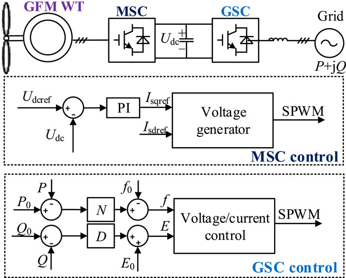
Figure 1. Schematic structure of a typical GFM WPS.
2.1 The Q-U droop control of GFM WPSs
When the sum of the inverter equivalent output impedances in GFM WPSs is inductive, the reactive power output from the inverter becomes a primary function of the bus voltage magnitude, so the Q-U droop characteristic equation for GFM WPSs can be described as follows:
where
The value of
2.2 Equivalent circuit
In order to analyze the effect of the GFM wind turbine on the grid voltage, the GFM wind turbine is equated to the form of a three-phase AC voltage source with the phase of the GFM wind turbine as the initial phase while focusing only on the external characteristics of the wind turbine. For the grid side, it can also be equated to the form of a three-phase AC source and disassembled into the form of a superposition of active and reactive power, and the power system can be equated to a single system of GFM wind turbines, as shown in Figure 2, under the premise of considering only the GFM wind turbines and the grid. In Figure 2,
where
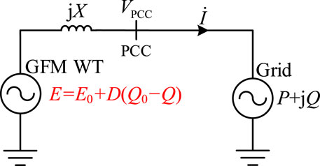
Figure 2. Equivalent circuit of the GFM WPS.
3 Modeling of voltage response
According to Kirchhoff’s voltage law (KVL), the equivalent circuit voltage equation is
Taking the phase angle of the voltage at the PCC as a reference and assuming that the phase angle of the terminal voltage at the turbine-side is
The equivalent current can be expressed in Equation 7.
For the load-side satisfying Equation 8
Then, the active and reactive power at the load-side can be expressed in Equation 9.
Further organizing leads to the following expression which is shown in Equation 10.
Combined with the trigonometric theorem, the above expression can be which is shown in Equation 11.
Furthermore, the square of the voltage magnitude
Mathematically, the following expression needs to be satisfied in order to keep the calculations correct:
Further collation yields the following results which is shown in Equation 14.
Combining the above determining conditions, the square of the voltage magnitude
The above expression is determined by the establishment condition, i.e.,
Combining the above condition criteria, the calculation result needs to satisfy
Substituting Equation 1 into Equation 17 yields the following expression for the voltage magnitude at the point of common coupling which is shown in Equation 18.
Combining the above expressions and assuming initial operating conditions where the droop coefficient
Under the condition that the initial working condition is known, in order to facilitate the calculation of voltage magnitude under different working conditions, the expression of voltage magnitude at the point of common coupling is normalized, which can be expressed as follows:
4 Voltage response influencing factors and mechanism analysis
According to Equation 20, the voltage amplitude
4.1 Effect of active power on voltage magnitude at PCC
According to Figure 3, it can be seen that with the increase in active power
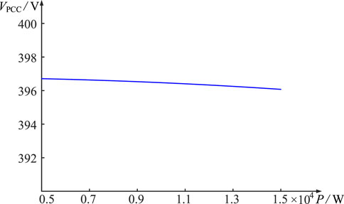
Figure 3. Curve of voltage amplitude at PCC with varying active power.
4.2 Effect of reactive power on voltage magnitude at PCC
According to Figure 4, it can be seen that as the reactive power
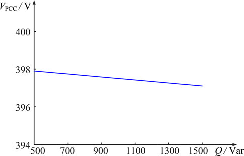
Figure 4. Curve of voltage amplitude at PCC with varying reactive power.
4.3 Effect of equivalent reactance on voltage magnitude at PCC
In order to investigate the effect of the
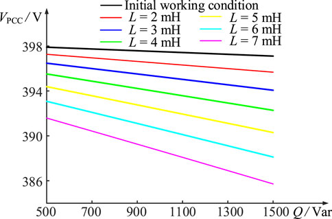
Figure 5. Curve of voltage amplitude at PCC with varying equivalent reactance.
According to Figure 5, it can be seen that with the increase in the value of
4.4 Effect of droop coefficient on voltage magnitude at PCC
In order to study the effect of the
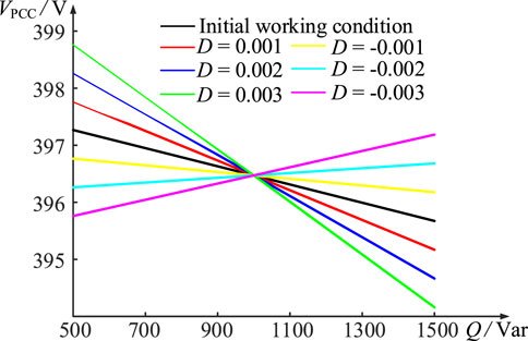
Figure 6. Curve of voltage amplitude at PCC with varying droop coefficient.
According to Figure 6, it can be seen that
Moreover, in order to achieve better voltage stabilization and explore the reasonableness of the value of
Predicting the value of
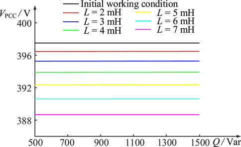
Figure 7. Curve of voltage amplitude at PCC with equivalent reactance and droop coefficient interacting cooperatively.
From Figure 7, it can be seen that under the influence of
5 Verification
A single WPS was built in the MATLAB/Simulink platform to verify the influence of each influencing factor on the voltage at the point of common coupling in Figure 8. Two simulation conditions were set up to prove the correctness of the above analysis. The specific parameters under the initial working condition are shown in Tables 1, 2.
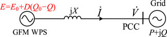
Figure 8. Circuit structure of the tested WPS.
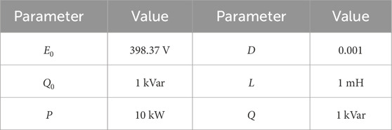
Table 1. Simulation model structural parameters of case 1.
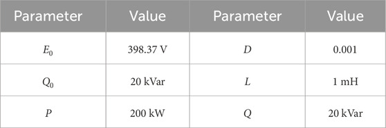
Table 2. Simulation model structural parameters of case 2.
Combined with Figures 9, 10, it can be seen that the change in load reactive power
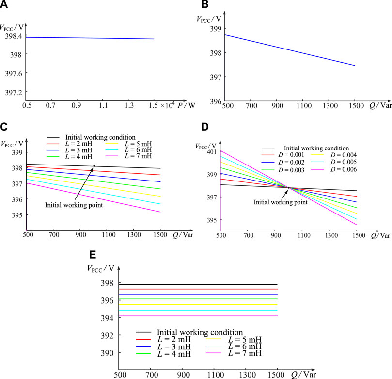
Figure 9. Curve of PCC voltage with different effect factors of case 1. (A) Active power. (B) Reactive power. (C) Equivalent reactance. (D) Droop coefficient. (E) Equivalent reactance and droop coefficient interacting cooperatively.
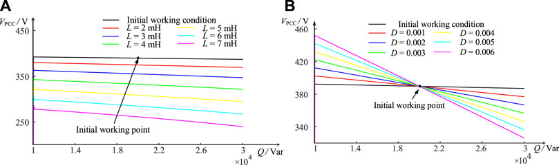
Figure 10. Curve of PCC voltage with different effect factors of case 2. (A) Equivalent reactance. (B) Droop coefficient.
Specifically, in the case of constant inverter equivalent output reactance
These phenomena are inextricably linked to the
In order to better reflect the impact of the effect factors on
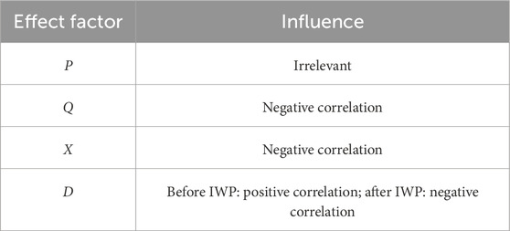
Table 3. Impact of effect factors on
6 Conclusion
In this study, the voltage response characteristics of the system at the point of common coupling and the voltage stabilization strategy are investigated by modeling analysis and simulation verification with GFM WPS as the research object. The main conclusions are as follows:
1) The voltage response circuit model and mathematical model of the system are established; the expression for the voltage magnitude
2) The voltage stabilization method is further investigated by analyzing the expression for the voltage magnitude
3) The simulation verification of the influencing elements and voltage stabilization method is performed using the MATLAB/Simulink platform, and the above influencing factors and the proposed voltage stabilization strategy were verified, which proved the reliability of the analysis. At the same time, it provides a theoretical foundation for solving the voltage stabilization support problem in a new energy GFM system.
Data availability statement
The original contributions presented in the study are included in the article/Supplementary Material; further inquiries can be directed to the corresponding authors.
Author contributions
QuL: conceptualization, data curation, formal analysis, funding acquisition, investigation, methodology, project administration, resources, software, supervision, validation, visualization, writing–original draft, and writing–review and editing. QiL: conceptualization, data curation, investigation, software, validation, and writing–review and editing. WT: formal analysis, investigation, project administration, and writing–review and editing. CW: supervision, visualization, and writing–review and editing.
Funding
The author(s) declare that financial support was received for the research, authorship, and/or publication of this article. This work was supported by the science and technology project of the State Grid Jiangsu Electric Power Co., Ltd. (J2023021).
Acknowledgments
The authors wish to thank the science and technology project of the State Grid Jiangsu Electric Power Co., Ltd., for the project funding (J2023021).
Conflict of interest
Authors QuL, QiL, WT, and CW were employed by State Grid Jiangsu Electric Power Co., Ltd.
The authors declare that this study received funding from State Grid Jiangsu Electric Power Co., Ltd. The funder had the following involvement in the study: the study design, collection, analysis, interpretation of data, and the writing of this article.
Publisher’s note
All claims expressed in this article are solely those of the authors and do not necessarily represent those of their affiliated organizations, or those of the publisher, the editors, and the reviewers. Any product that may be evaluated in this article, or claim that may be made by its manufacturer, is not guaranteed or endorsed by the publisher.
References
Fang, J., Li, H., Tang, Y., and Blaabjerg, F. (2018). Distributed power system virtual inertia implemented by grid-connected power converters. IEEE Trans. Power Electron. 33, 8488–8499. doi:10.1109/tpel.2017.2785218
Kang, C., and Yao, L. (2017). Key scientific issues and theoretical research framework for power systems with high proportion of renewable energy. Dianli Xit. Zidonghua/Automation Electr. Power Syst. 41, 2–11.
Kim, G. G., Hyun, J. H., Choi, J. H., ahn, S.-H., Bhang, B. G., and Ahn, H.-K. (2023). Quality analysis of photovoltaic system using descriptive statistics of power performance index. IEEE Access 11, 28427–28438. doi:10.1109/access.2023.3257373
Leon, A. E., Nozal, Ã. R. d., and Mauricio, J. M. (2024). Frequency support strategy for fast response energy storage systems. IEEE Trans. Power Syst. 39, 5439–5442. doi:10.1109/tpwrs.2024.3358631
Li, Y., Hu, J., Wen, W., Wang, Q., Ma, S., and Guo, J. (2022). Concept and definition of dynamic symmetrical components with time-varying amplitude and frequency. IEEE Trans. Energy Convers. 37, 2737–2748. doi:10.1109/tec.2022.3188864
Liu, T., Chen, A., Gao, F., Liu, X., Li, X., and Hu, S. (2022). Double-loop control strategy with cascaded model predictive control to improve frequency regulation for islanded microgrids. IEEE Trans. Smart Grid 13, 3954–3967. doi:10.1109/tsg.2021.3129220
Liu, T., and Wang, X. (2021). Transient stability of single-loop voltage-magnitude controlled grid-forming converters. IEEE Trans. Power Electron. 36, 6158–6162. doi:10.1109/tpel.2020.3034288
Luo, C., Ma, X., Liu, T., and Wang, X. (2023). Adaptive-output-voltage-regulation-based solution for the dc-link undervoltage of grid-forming inverters. IEEE Trans. Power Electron. 38, 12559–12569. doi:10.1109/tpel.2023.3298468
Ouyang, J., Li, M., Zhang, Z., and Tang, T. (2019). Multi-timescale active and reactive power-coordinated control of large-scale wind integrated power system for severe wind speed fluctuation. IEEE Access 7, 51201–51210. doi:10.1109/access.2019.2911587
Pal, A., Pal, D., and Panigrahi, B. K. (2023). A current saturation strategy for enhancing the low voltage ride-through capability of grid-forming inverters. IEEE Trans. Circuits Syst. II Express Briefs 70, 1009–1013. doi:10.1109/tcsii.2022.3221134
Rosso, R., Wang, X., Liserre, M., Lu, X., and Engelken, S. (2021). Grid-forming converters: control approaches, grid-synchronization, and future trends—a review. IEEE Open J. Industry Appl. 2, 93–109. doi:10.1109/ojia.2021.3074028
Shang, L., Dong, X., Liu, C., and Gong, Z. (2021). Fast grid frequency and voltage control of battery energy storage system based on the amplitude-phase-locked-loop. IEEE Trans. Smart Grid 13, 941–953. doi:10.1109/tsg.2021.3133580
Shang, L., Hua, Z., Liu, C., and Dong, X. (2022). Amplitude-phase-locked-loop-based power injection strategy for wind power generation under three-phase grid fault. IEEE Trans. Energy Convers. 37, 2952–2961. doi:10.1109/tec.2022.3207285
Shao, H., Cai, X., Zhou, D., Li, Z., Zheng, D., Cao, Y., et al. (2019). Equivalent modeling and comprehensive evaluation of inertia emulation control strategy for dfig wind turbine generator. IEEE Access 7, 64798–64811. doi:10.1109/access.2019.2917334
Verma, P., K, S., and Dwivedi, B. (2023). A self-regulating virtual synchronous generator control of doubly fed induction generator-wind farms. IEEE Can. J. Electr. Comput. Eng. 46, 35–43. doi:10.1109/icjece.2022.3223510
Wu, H., and Wang, X. (2021). Passivity-based dual-loop vector voltage and current control for grid-forming vscs. IEEE Trans. Power Electron. 36, 8647–8652. doi:10.1109/tpel.2020.3048239
Xi, J., Geng, H., and Zou, X. (2021). Decoupling scheme for virtual synchronous generator controlled wind farms participating in inertial response. J. Mod. Power Syst. Clean Energy 9, 347–355. doi:10.35833/mpce.2019.000341
Xiong, L., Liu, X., Zhang, D., and Liu, Y. (2021). Rapid power compensation-based frequency response strategy for low-inertia power systems. IEEE J. Emerg. Sel. Top. Power Electron. 9, 4500–4513. doi:10.1109/jestpe.2020.3032063
Xiong, L., Liu, X., Zhao, C., and Zhuo, F. (2020). A fast and robust real-time detection algorithm of decaying dc transient and harmonic components in three-phase systems. IEEE Trans. Power Electron. 35, 3332–3336. doi:10.1109/tpel.2019.2940891
Xiong, L., Zhuo, F., Wang, F., Liu, X., Chen, Y., Zhu, M., et al. (2016). Static synchronous generator model: a new perspective to investigate dynamic characteristics and stability issues of grid-tied pwm inverter. IEEE Trans. Power Electron. 31, 6264–6280. doi:10.1109/tpel.2015.2498933
Keywords: grid-forming, wind power systems, voltage response, droop control, voltage stability
Citation: Li Q, Li Q, Tang W and Wang C (2024) Voltage response characterization of grid-forming wind power systems. Front. Energy Res. 12:1429295. doi: 10.3389/fenrg.2024.1429295
Received: 07 May 2024; Accepted: 08 July 2024;
Published: 01 August 2024.
Edited by:
Yonghui Liu, Hong Kong Polytechnic University, Hong Kong SAR, ChinaReviewed by:
Xiaokang Liu, Polytechnic University of Milan, ItalyHong Cencen, Nanjing Institute of Technology (NJIT), China
Huimin Wang, Zhejiang Sci-Tech University, China
Tong Wang, Hubei University of Economics, China
Copyright © 2024 Li, Li, Tang and Wang. This is an open-access article distributed under the terms of the Creative Commons Attribution License (CC BY). The use, distribution or reproduction in other forums is permitted, provided the original author(s) and the copyright owner(s) are credited and that the original publication in this journal is cited, in accordance with accepted academic practice. No use, distribution or reproduction is permitted which does not comply with these terms.
*Correspondence: Qun Li, cXVuX2xpQHNpbmEuY29t; Weijia Tang, dGFuZ19qc2VwY0AxMjYuY29t