 Dongxu Zhou1*
 Guangsheng Pan
 Zhongfan Gu
- 1State Grid Nanjing Power Supply Company, Information and Communication Branch, Nanjing, China
- 2School of Electrical Engineering, Southeast University, Nanjing, China
This article presents a study on the distributed optimization operation method for micro-energy grid clusters within an electric, thermal, and hydrogen integrated energy system. The research focuses on precisely modeling the Power-to-Hydrogen (P2H) conversion process in electrolytic cells by considering their startup characteristics. An optimization operation model is established, with each micro-energy grid as the principal entity, to cater to their individual interests and demands. The Alternating Direction Method of Multipliers (ADMM) algorithm is adopted for distributed solution. Case studies demonstrate that the connection topology between micro-energy grids significantly impacts the total operating cost, and the effectiveness of the ADMM algorithm is validated through a comparison with centralized optimization approaches.
1 Introduction
By 2050, the projected increment in CO2 emissions could span from 2.21 to 7.43 megatons, underscoring the urgency for decisive action. Amidst this backdrop, numerous nations worldwide have set forth ambitious carbon reduction targets, signaling a global commitment to mitigate climate change (Jiang et al., 2024). The Integrated Energy System (IES), a holistic approach that integrates power-to-heat conversion technologies and seamlessly intertwines heat and power generation, has emerged as a cornerstone in the pursuit of carbon emission reduction. This system, bolstered by its unique technological prowess, offers a pivotal pathway towards a greener future (Zhang et al., 2024).
The strategic deployment of complementary technologies within the IES framework further enhances renewable energy utilization, thereby mitigating adverse climate impacts (Pan et al., 2021). Among these, Power-to-Hydrogen (P2H) technology stands out as a highly efficient energy conversion mechanism, transforming electrical energy into hydrogen energy—a clean and versatile fuel source (Gu et al., 2024). As renewable energy capacity expands and electric vehicles, alongside other power-hungry devices, gain widespread adoption, the challenge of effectively managing surplus electricity has become paramount in the energy sector. P2H technology adeptly addresses this challenge by electrolyzing water, converting excess electrical energy into hydrogen, thereby not only alleviating the issue of surplus electricity but also supplying a clean, green energy source for innovative applications like hydrogen-fueled vehicles. Moreover, P2H technology boasts several advantages that make it an attractive option for energy storage and conversion. Its high energy storage efficiency, prolonged storage capability, and zero-emission profile position it as a promising contender in the quest for sustainable energy solutions (Zhuang et al., 2023). By harnessing the full potential of both the IES and P2H technology, we can accelerate our transition towards a low-carbon, environmentally friendly future.
(He et al., 2021) proposes an integrated energy system optimization model that utilizes P2H technology to convert excess wind power into hydrogen, mitigating curtailment and filling load valleys. Case studies validate the effectiveness of this approach. Author in (Gu et al., 2023) propose a regional joint electrolytic hydrogen system framework to address differentiated electrolytic hydrogen capacity caused by resource characteristics in China. They established a decoupling model for cascade hydropower and compared its advantages over separate systems in terms of reducing hydrogen costs, carbon emissions, and renewable energy capacity. Differential models for electrolyzers were also established, providing insights into their evolution and development prospects (Gupta et al., 2023). studies the integration of P2H technology into utility-scale hybrid power plants (HPPs) consisting of wind, solar, and battery storage. As renewable energy resources and sector coupling increase, HPPs are evolving to include other energy vectors like heat and gas storage. Integrating P2H within HPPs reduces fluctuations from non-dispatchable production and curtailment, similar to storage devices. Case studies in Europe demonstrate the significant techno-economic benefits of HPPs with P2H. In (Zhao et al., 2022), the Integrated Energy Production Unit (IEPU) concept, combining P2H and Carbon Capture, Utilization, and Storage (CCUS) technologies, is proposed. This concept leverages existing synchronous turbines to provide synthetic active and reactive capabilities, validated using open-source software with European load data, optimizing capacity and simulating 8,760-h operations to minimize annual costs. In (Dong et al., 2023), the authors compare the technical characteristics of alkaline electrolyzers (AEC) and proton exchange membrane electrolyzers (PEMEC), and proposes an optimal planning model for P2H clusters. The model aims to minimize investment, operational, startup/shutdown, grid power purchase, network loss, and voltage deviation costs. A modified IEEE 33-node network case verifies the model’s effectiveness and benefits (Lu et al., 2022). introduces an Approximate Dynamic Programming (ADP) method for optimizing real-time micro-energy grid operation with P2H devices. The ADP approach, leveraging a piecewise linear function, finds near-optimal strategies that adapt to uncertainties, outperforming Model Predictive Control (MPC) in case studies. Authors in (Cao et al., 2022) propose a dual-fuel cells hydrogen energy storage integrated energy system to enhance performance. Optimizing device capacities based on economic factors reveals an optimal configuration that outperforms single fuel cells. Sensitivity analysis highlights the influence of electricity, natural gas prices, and renewable energy capacity on the optimal hydrogen storage and fuel cell configuration.
However, a significant oversight in existing research lies in the neglect of electrolytic cells’ start-up characteristics, notably the start-up delay and power requirements. While these cells are indispensable in converting renewable energy sources into hydrogen via the Power-to-Hydrogen (P2H) process, their initial operational phases, particularly the intricate start-up process, have remained largely unexamined. This oversight results in a lack of granularity in electrolytic cell models, which in turn fails to accurately mirror the system’s true operational dynamics. This uncharted territory represents a crucial gap that necessitates urgent attention and further exploration. Such endeavors would not only refine our understanding of these systems but also propel us closer to a greener, more sustainable future by ensuring that P2H technologies operate at their optimal capacity.
The Alternating Direction Method of Multipliers (ADMM) algorithm, renowned for its prowess in tackling optimization challenges, stands out as a formidable tool for resolving large-scale, decentralized, and intricate constraint optimization problems within the energy sector. Its unparalleled advantages have fostered widespread adoption in energy optimization applications. By masterfully decomposing intricate energy systems into manageable subproblems and iteratively solving them in an alternating fashion, the ADMM algorithm drastically reduces problem complexity and computational overhead. Moreover, its inherent distributed nature harmoniously aligns with the decentralized characteristics of energy systems, enabling seamless distributed optimization management, thereby enhancing overall system efficiency and performance.
(Huang et al., 2023) proposes a blockchain-based distributed market framework for the bi-level carbon and energy trading between coal mine integrated energy systems and a virtual power plant (VPP). (Kong et al., 2020) introduces a distributed optimization approach for integrated energy systems (IES) using the ADMM. The method begins by analyzing uncertain factors from energy sources and loads, employing scenario analysis to capture their stochasticity. An optimal scheduling model for IES is then formulated. Leveraging ADMM, this model is reformulated to enable distributed optimization for multi-energy complementation. Case study results demonstrate the effectiveness and practicality of the proposed strategy. Authors in (Chen et al., 2018) propose an enhanced energy hub (EH) model for IES, incorporating electric and heat energy storage along with solar thermal collectors. The IES is structured as a multi-operator system, with each EH belonging to a distinct operator. A distributed energy management model accounts for storage operation costs and shows effectiveness in reducing energy bills, transmission losses, and prolonging energy storage life. (Pan et al., 2022) offers a distributed operation strategy using an enhanced ADMM. It establishes models for gas turbines and energy storage, incorporating dynamic characteristics of radial distribution and natural gas networks. An optimization model for day-ahead scheduling reduces operating costs while managing renewable energy uncertainty through chance constraints. An ADMM-based distributed operation method with adaptive step size addresses information opacity between electricity and gas systems. (Wu et al., 2021) addresses the challenges of centralized control in large-scale integrated energy parks by proposing a distributed computing method. The method decomposes joint scheduling into subproblems, considers the coupling of electricity, gas, and heat, and establishes a day-ahead scheduling model. A case study demonstrates the feasibility of the distributed optimization model. Authors in (Li et al., 2024) propose an optimal operation strategy with dynamic partitioning for centralized shared energy storage stations, considering day-ahead demands of renewable energy power plants. A multi-entity cooperative optimization model based on Nash bargaining theory is implemented and decomposed into subproblems solved by ADMM. Simulations show improved tracking of renewable energy output, higher energy storage utilization, and increased profits for each entity.
In this article, we delve into a comprehensive study exploring the distributed optimization operation methodology for clusters of micro-energy grids within a multifaceted energy system that integrates electricity, heat, and hydrogen resources. Our research meticulously models the intricate Power-to-Hydrogen (P2H) conversion process within electrolytic cells, meticulously accounting for their nuanced startup dynamics. This nuanced approach ensures a precise portrayal of the P2H process, pivotal for optimizing the holistic energy system’s performance. To this end, we formulate an optimization framework that recognizes each micro-energy grid as an autonomous entity, respecting their distinct interests and operational imperatives. This model not only considers the efficiency of energy conversion but also the specific operational constraints and goals of each micro-energy grid. To tackle this intricate distributed optimization challenge, we harness the power of the Alternating Direction Method of Multipliers (ADMM) algorithm, renowned for its prowess in handling large-scale, decentralized optimization problems. By utilizing ADMM, we can decompose the overall optimization problem into smaller subproblems, which are then solved iteratively in a distributed manner. This approach not only reduces the computational complexity but also enables each micro-energy grid to operate independently while still contributing to the overall optimization of the entire energy system.
2 P2H module unified operation model
2.1 Introduction for P2H technologies
In the commercial landscape of hydrogen production equipment, the electrolytic cell stack stands as the cornerstone unit. Nevertheless, the inherent power limitations of a solitary stack, often constrained to below 10 kW, underscore the need for scalability. By harnessing the inherent scalability of electrolytic cell technology, we can orchestrate multiple stacks into formidable modules, capable of achieving capacities that soar from 100 kW to the megawatt realm. The extensive hydrogen production systems utilized in power systems often comprise numerous independently managed modules, where each module can be selectively activated, deactivated, and its output precisely controlled. Therefore, this paper focuses its modeling and selection planning efforts on the electric hydrogen production module as the fundamental research subject.
2.2 Startup model of P2H modules
When initiating the P2H process, the start-up delay associated with low-temperature electrolysis technologies, such as AEC and PEMEC, tends to be minimal. However, in the case of SOEC utilizing high-temperature electrolysis, hydrogen gas production does not commence until the stack has reached a specific temperature threshold. Notably, the heating duration required to attain this temperature can often be significant and should not be overlooked.
In the context of the given modeling,
The modeling of these variables allows for a comprehensive representation of the dynamic behavior and operational decisions within the integrated energy system.
The operating power of the EC is subject to upper and lower limits, which are mathematically constrained as expressed in Equation 1. This constraint ensures that the electrolytic cell operates within its safe and efficient range, preventing over- or under-utilization.
where
The starting power constraint of EC is shown in Equation 2.
where
The state constraints of EC are shown in Equation 3.
In Equation 3, the first equation represents the constraints imposed by the start-up and shutdown action variables on the state variables of the electrolytic cell. The second equation indicates that the electrolytic cell can only be started when it is in the off state, while the third equation indicates that the electrolytic cell can only be shut down when it is in the start-up state.
2.3 Comparison of main performance indicators of 3 P2H technologies
At present, there are three main types of electrolytic cells: alkaline electrolytic cells (AECs), proton exchange membrane electrolytic cells (PEMECs), and solid oxide electrolytic cells (SOECs).
Among the three P2H technologies, AECs boast the earliest research and development efforts, the most matured technology, and the lowest equipment cost. Nonetheless, they encounter challenges such as the difficulty in completely isolating hydrogen-oxygen diffusion (especially under low loads), high electrolysis overvoltage, and the inertia of load ion conduction in electrolyte solutions. These factors limit their working load range and response speed.
In contrast, PEMECs have significantly improved load range and response speed compared to AECs, albeit with a slightly higher equipment cost. However, both AECs and PEMECs share a limitation: their rated hydrogen production efficiency does not exceed 70%.
SOECs, on the other hand, utilize solid oxide electrolytes to electrolyze gaseous water in high-temperature environments. By harnessing the thermodynamics and kinetics of the electrolysis reaction, SOECs are able to improve energy conversion efficiency by approximately 10%–15%. However, due to the constraints of operating in high-temperature environments, SOEC technology currently lags behind PEMECs in terms of cost and response speed.
Table 1 below provides a concise overview of the key technical indicators associated with each of the three electrolytic cells. It is evident that each of the three P2H technologies offers distinct advantages: AEC excels in cost-efficiency, PEMEC stands out in terms of flexibility, while SOEC boasts the highest energy conversion efficiency.

Table 1. The main technical indicators of the three electrolytic cells.
3 Mathematical model for the optimal operation of micro-energy grids
3.1 System structure
The micro-energy grid incorporates a busbar design that comprises four essential power busbars: electricity, heat, hydrogen, and gas, as shown in Figure 1.

Figure 1. The structure of each micro-energy grid.
Within this micro-energy grid, the primary energy supply apparatus encompasses a harmonious blend of renewable energy generation systems and CHP units. Furthermore, the system is augmented by EH techniques and GB, enhancing the thermal energy supply capabilities. Within this intricate system, devices such as EC and FC play pivotal roles, facilitating seamless interconversion between electrical and hydrogen energy. Notably, the hydrogen energy generation process inherently yields thermal energy, thus further augmenting the grid’s thermal output. Moreover, the refined hydrogen energy can undergo MR for conversion into natural gas, expanding the grid’s energy portfolio.
This versatile micro-energy grid caters to three primary load demands: electrical energy, hydrogen energy, and thermal energy, ensuring a comprehensive range of energy services. Its input energy sources are diverse, incorporating electricity sourced directly from the main power grid or exchanged with other micro-energy grids, as well as natural gas procured efficiently from gas utility companies. This integrated approach fosters a resilient and sustainable energy ecosystem, tailored to meet the evolving needs of modern communities.
The article delves into an integrated energy system encompassing electric, thermal, and hydrogen components, which comprises a cluster of interconnected micro-energy grids, as depicted in Figure 2. These micro-energy grids are capable of exchanging electrical power seamlessly through dedicated interconnection lines, fostering a dynamic and interactive network.
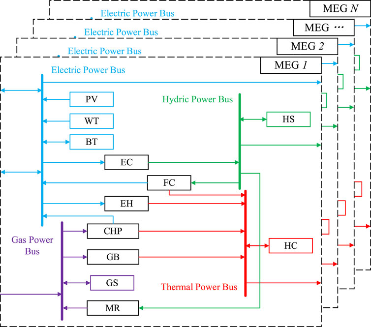
Figure 2. The structure of micro-energy grid cluster.
3.2 Objective function
For each micro-energy grid, the overarching objective is to minimize operating costs, as outlined in Equation 4. These costs comprise four distinct components: operational and maintenance costs, gas procurement costs, electricity acquisition costs, and power exchange costs.
where
The operational and maintenance costs are shown in Equations 5, 6.
The gas procurement costs are illustrated in Equation 7.
The electricity acquisition costs from the power grid are shown in Equation 8.
The power exchange costs with other micro-energy grids are shown in Equation 9.
3.3 Constraints
3.3.1 Constraints on the power balance
The electric power balance is shown in Equation 10.
The thermal power balance is shown in Equation 11.
The hydric power balance is shown in Equation 12.
The gas power balance is shown in Equation 13.
3.3.2 Constraints on the purchased power of electricity and gas
The purchased/sold electric power constraints from/to the power grid are shown in Equation 14.
The purchased gas power constraints from the gas company are shown in Equation 15.
3.3.3 Constraints on the efficiency of the devices
The efficiency constraints of the devices are shown in Equation 16.
3.3.4 Constraints on the upper and lower power limits of the devices
The upper and lower power limit constraints are shown in Equation 17.
3.3.5 Constraints on the ramping limit
The ramping limit constraints are shown in Equation 18.
3.3.6 Constraints on the energy storage devices
The limitations pertaining to the energy storage device are delineated in Equations 19–21. Specifically, Equation 19 encapsulates the efficiency constraint during charging and discharging operations, Equation 20 outlines the upper and lower bounds for the charging and discharging power, and Equation 21 specifies the energy capacity constraint of the storage device.
3.3.7 Constraints on the operation of the EC
As outlined in Section 3.2, the EC’s upper and lower power constraints, initial power constraints, and start-stop state limitations are defined in Equations 22, 23. Furthermore, Equation 24 stipulates that the start-stop state must remain consistent at the beginning and end of each cycle, while Equation 25 imposes a maximum limit on the number of starts and stops that can occur within a single cycle.
3.3.8 Constraints on the exchanged power with other micro-energy grids
Equation 26 establishes the upper and lower bounds for the interactive power exchange with other micro-energy grids. Meanwhile, Equation 27 stipulates that the diagonal elements of the interaction state matrix must be zero, indicating that a grid cannot interact with itself, and furthermore, there can be no more than one input and one output state that is assigned a value of 1, signifying a single connection for power exchange in either direction.
4 Algorithm for solving the multi-agent collaborative optimization model
4.1 ADMM algorithm
As a distributed algorithm, ADMM excels in addressing large-scale separable optimization problems by systematically breaking them down into smaller subproblems. This strategic decomposition not only simplifies the complexity but also paves the way for the precise identification of the elusive global optimal solution. The method seamlessly integrates the decomposition principles of the dual ascent method with the superior convergence properties of the Lagrange multiplier method, creating a potent synergy that ensures both robustness and unparalleled effectiveness.
The process of solving the problem shown in Equation 28 using the ADMM algorithm is as follows.
where
Split decision variable
where
By incorporating a quadratic penalty term into the Lagrangian function, an augmented Lagrangian function is derived, providing an enhanced framework for addressing optimization problems, which is shown in Equation 30:
where
Alternately solve variables
where
4.2 Multi agent optimal operation model based on ADMM algorithm
Utilizing the mathematical model outlined in Chapter 3 for the optimal operation of micro-energy grids, and leveraging the power of the ADMM algorithm, the objective function is restructured in the following manner, as illustrated in Equation 32:
where
The constraints specified in Equation 10 through Equation 27 maintain their original form and remain unaltered.
4.3 The solving process
The process of employing the ADMM algorithm to address this problem is outlined below:
1. Start with
2. Solve each subproblem individually.
3. Update the coordination variables
4. Compute the primal residual
5. Adjust the penalty factors
6. Update the dual multipliers
Repeat steps 2 through 6 until the desired convergence criteria are met.
5 Case studies
5.1 Description of the scenarios
In the case studies, three distinct operational scenarios were delineated: fully connected, partially connected, and independent operation, as depicted in Figure 3. The objective was to delve into the implications of varying connection topologies on the operational efficiency of micro-energy grid clusters. Specifically, in each of these scenarios, micro-energy grid 2 experienced a higher load level, micro-energy grid 3 boasted a larger capacity for hydrogen production devices, and micro-energy grid 4 generated a more significant amount of renewable energy.
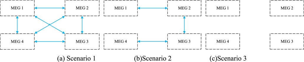
Figure 3. (A) Scenario 1 (B) Scenario 2 (C) Scenario 3. The connection topology between the micro-energy grids in each scenario.
The cost of procuring electricity from the power grid is determined by the time-of-use pricing model, as outlined in Table 2. Meanwhile, Table 3 provides a comprehensive overview of the installed devices capacity within each micro-energy grid.
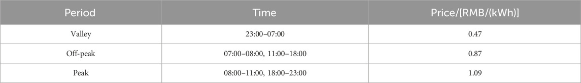
Table 2. TOU electricity price.
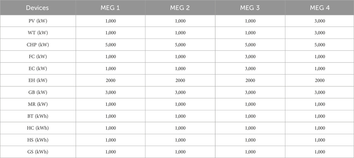
Table 3. Capacity of the devices installed in each micro-energy grid.
5.2 Convergence analysis
The convergence curves for the ADMM under Scenario 1 and Scenario 2 are presented in Figures 4, 5 respectively. As evident from the graphs, after exceeding ten iterations, the algorithm successfully converges to the designated threshold.
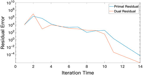
Figure 4. The variation of residual error with the iteration times in scenario 1
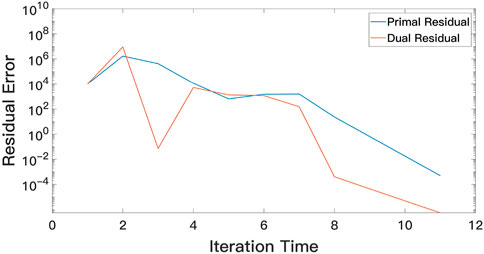
Figure 5. The variation of residual error with the iteration times in scenario 2.
Furthermore, in Scenario 3, where the 4 micro-energy grids operate independently, the exchanged power between them inevitably amounts to 0. Consequently, the ADMM algorithm achieves convergence after the initial iteration.
5.3 Economic analysis
Table 4 presents a comparative analysis of the total costs incurred by the ADMM algorithm and the centralized optimization method across three distinct scenarios. Notably, it is evident that in each of these scenarios, the ADMM algorithm’s error margin remains consistently below 1%, thus conclusively affirming the robustness and effectiveness of the proposed algorithm.
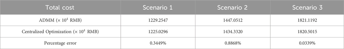
Table 4. Comparison of the optimization results between ADMM algorithm and centralized optimization method.
Tables 5–7 illustrate the breakdown of costs for each component of the micro-energy grids across three distinct scenarios. A noteworthy trend emerges, indicating that as the connection topology weakens, the total cost of micro-energy grid clusters rises incrementally. This underscores the pivotal role of power interchange between micro-energy grids in minimizing overall costs. Notably, micro-energy grid 2, which bears a heavier load, exhibits the most significant cost variation. The interaction of power between micro-energy grids substantially mitigates their electricity and gas procurement costs. Furthermore, despite micro-energy grid 1 and micro-energy grid 3 having comparable load levels, their costs differ due to the presence of electric hydrogen production equipment in the latter, which facilitates the storage of a portion of electrical energy.
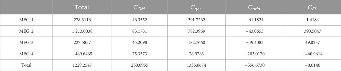
Table 5. The costs of each part of each micro-energy grid in scenario 1 (
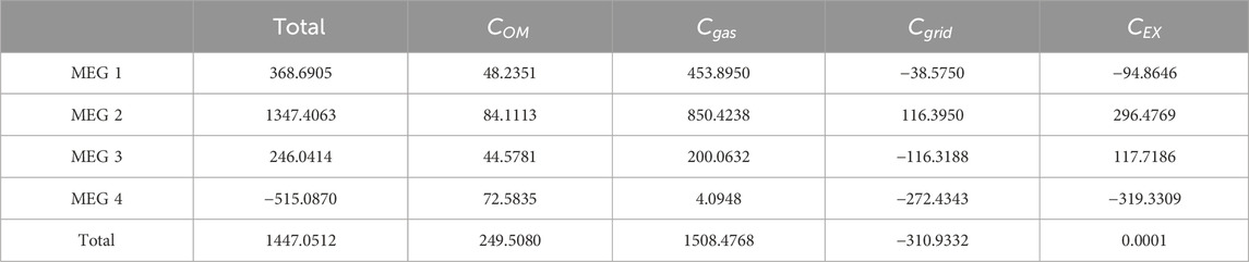
Table 6. The costs of each part of each micro-energy grid in scenario 2 (
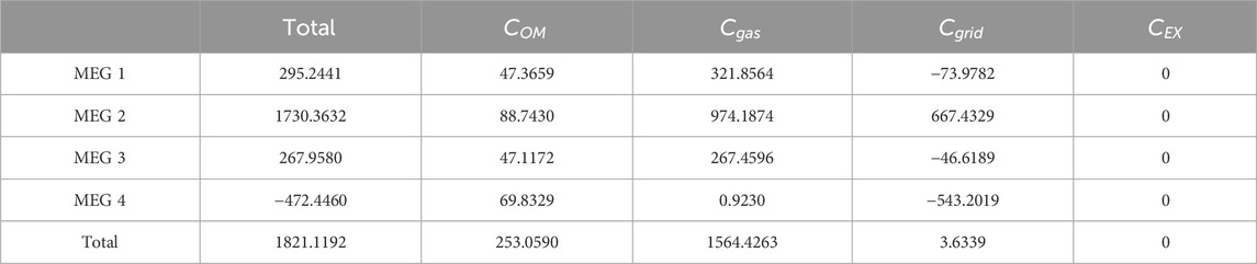
Table 7. The costs of each part of each micro-energy grid in scenario 3 (
5.4 Operation analysis
Figures 6–8 illustrate the operational dynamics of micro-energy grid clusters across three distinct scenarios. Notably, apart from renewable energy generation, CHP emerges as the primary source of electricity, while CHP and EH jointly constitute the main supply methods for thermal energy. As the interconnection topology between micro-energy grids weakens, a noteworthy surge in the output of CHP and grid-purchased power is observed. This increase arises from the inability to transmit excess electricity to other micro-energy grids via connecting lines, leading to its sale to the grid. Consequentially, this trend also prompts an augmentation in gas purchasing power. Additionally, energy storage devices play a pivotal role in effectively managing peak and valley load conditions, enabling effective load shaving and valley filling.
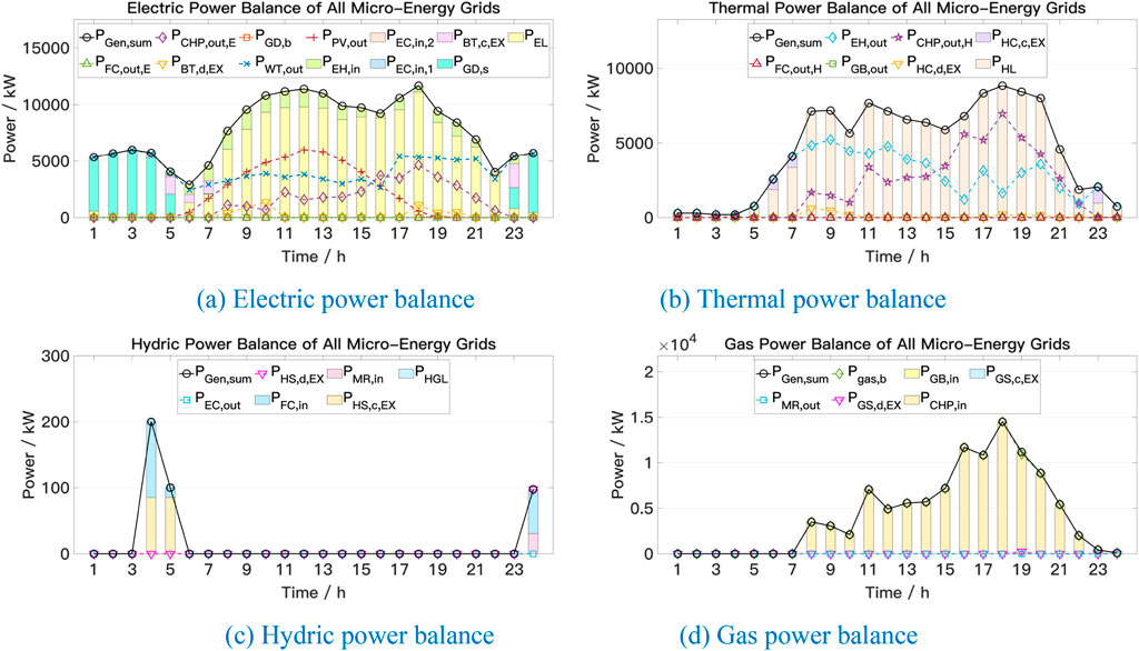
Figure 6. (A) Electric power balance (B) Thermal power balance (C) Hydric power balance (D) Gas power balance. The energy supply and consumption situation of the micro-energy grid cluster in scenario 1.
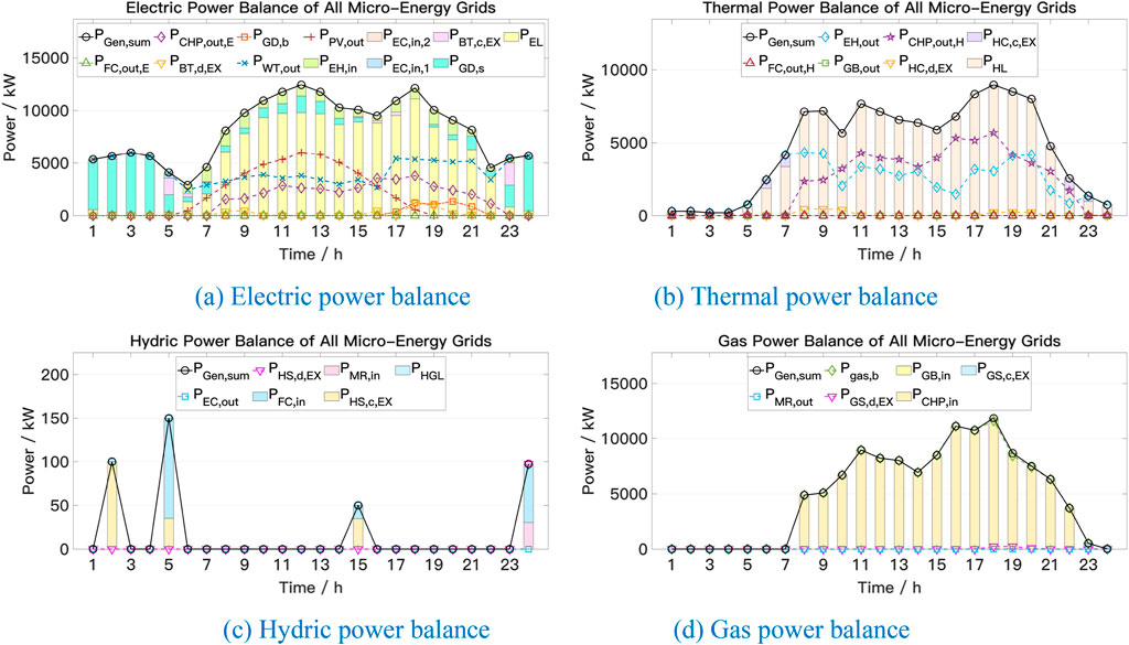
Figure 7. (A) Electric power balance (B) Thermal power balance. (C) Hydric power balance (D) Gas power balance. The energy supply and consumption situation of the micro-energy grid cluster in scenario 2.
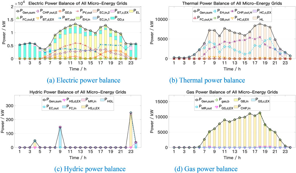
Figure 8. (A) Electric power balance (B) Thermal power balance. (C) Hydric power balance (D) Gas power balance. The energy supply and consumption situation of the micro-energy grid cluster in scenario 3.
6 Conclusion
This article delves into the distributed optimization operation method for micro-energy grid clusters, focusing on the integrated energy system encompassing electricity, heat, and hydrogen. In developing the mathematical model for the electrolytic cell, we accounted for its startup characteristics to ensure an accurate portrayal of the P2H conversion process. With regard to optimizing the model algorithms, we established an optimization operation model centered on each micro-energy grid, taking into consideration their respective interests and demands. For distributed solution, we employed the ADMM algorithm. A case analysis revealed that the variance in total operating costs, attributed to different connection topologies between micro-energy grids, could be as significant as 48.15%. Furthermore, a comparison with the results obtained from centralized optimization algorithms underscores the efficacy of the ADMM algorithm.
Data availability statement
The original contributions presented in the study are included in the article/supplementary material, further inquiries can be directed to the corresponding author.
Author contributions
DZ: Conceptualization, Data curation, Formal Analysis, Funding acquisition, Investigation, Methodology, Project administration, Resources, Software, Supervision, Validation, Visualization, Writing–original draft. JX: Data curation, Formal Analysis, Funding acquisition, Investigation, Methodology, Resources, Software, Writing–original draft. CZ: Data curation, Investigation, Methodology, Writing–original draft. PW: Data curation, Formal Analysis, Methodology, Software, Writing–original draft. GP: Methodology, Supervision, Writing–original draft. ZG: Methodology, Supervision, Writing–original draft.
Funding
The author(s) declare that financial support was received for the research, authorship, and/or publication of this article. The study was supported by “Science and Technology Project of State Grid Jiangsu Electric Power Co., Ltd. (Grant No. J2023072)”.
Conflict of interest
Authors DZ, JX, CZ, and PW were employed by State Grid Nanjing Power Supply Company.
The remaining authors declare that the research was conducted in the absence of any commercial or financial relationships that could be construed as a potential conflict of interest.
The authors declare that this study received funding from State Grid Jiangsu Electric Power Co., Ltd. The funder had the following involvement in the study: study design, data collection and analysis, writing of this article and decision to publish.
Publisher’s note
All claims expressed in this article are solely those of the authors and do not necessarily represent those of their affiliated organizations, or those of the publisher, the editors and the reviewers. Any product that may be evaluated in this article, or claim that may be made by its manufacturer, is not guaranteed or endorsed by the publisher.
References
Cao, W., Zhai, D., Zhang, J., Sha, H., Wang, Z., and Han, Q. (2022). “Study on optimal configuration of hydrogen energy storage IES with dual-fuel cells,” in 2022 4th international conference on electrical engineering and control technologies (CEECT), Shanghai, China, 16-18 December 2022 (IEEE), 939–946. doi:10.1109/CEECT55960.2022.10030112
Chen, Q., Xia, M., Chen, M., and Hu, H. (2018). Distributed energy management for integrated energy system considering multiple independent operators. Portland, OR, USA: IEEE Power & Energy Society General Meeting PESGM, 1–5. doi:10.1109/PESGM.2018.8586052
Dong, Y., Ma, Z., Wang, Q., Ma, S., and Han, Z. (2023). “Optimal planning of multi-electrolyzer power-to-hydrogen(P2H) clusters in distribution network,” in 2023 IEEE international conference on applied superconductivity and electromagnetic devices (ASEMD). Tianjin, China, October, 2023 (IEEE), 1–2. doi:10.1109/ASEMD59061.2023.10368814
Gu, Z., Pan, G., Gu, W., Qiu, H., and Lu, S. (2024). Robust optimization of scale and revenue for integrated power-to-hydrogen systems within energy, ancillary services, and hydrogen markets. IEEE Trans. Power Syst. 39 (3), 5008–5023. doi:10.1109/TPWRS.2023.3323660
Gu, Z., Pan, G., Gu, W., Zhou, S., Wu, Z., and Lu, S. (2023). Assessment and prospect of region joint electrolytic hydrogen systems considering multiple energy sources: wind, solar, hydro and thermal power. IEEE Trans. Industry Appl. 59 (5), 5269–5282. doi:10.1109/TIA.2023.3282923
Gupta, M., Das, K., Friis-Møller, M., and Leon, J. P. M. (2023). “Assessment of hybrid power plant operation including P2H in future energy markets,” in 22nd wind and solar integration workshop (WIW 2023). Copenhagen, Denmark, 289–294. doi:10.1049/icp.2023.2750
He, X., Lu, T., Li, Y., Wang, S., and Li, J. (2021). Collaborative planning of integrated energy system considering P2H technology. IEEE/IAS Industrial Commer. Power Syst. Asia (I&CPS Asia), 1219–1222. doi:10.1109/ICPSAsia52756.2021.9621567
Huang, H., Li, Z., Sampath, L. P. M. I., Yang, J., Nguyen, H. D., Gooi, H. B., et al. (2023). Blockchain-enabled carbon and energy trading for network-constrained coal mines with uncertainties. IEEE Trans. Sustain. Energy 14 (3), 1634–1647. doi:10.1109/TSTE.2023.3240203
Jiang, Y., Ren, Z., and Li, W. (2024). Committed carbon emission operation region for integrated energy systems: concepts and analyses. IEEE Trans. Sustain. Energy 15 (2), 1194–1209. doi:10.1109/TSTE.2023.3330857
Kong, A., Li, C., Chen, L., Zhu, X., and Xu, X. (2020). “ADMM-based distributed optimal dispatch of integrated energy system considering uncertainties of source and load,” in 2020 IEEE sustainable power and energy conference (iSPEC), Chengdu, China, 23–25 November 2020 (IEEE), 1222–1227. doi:10.1109/iSPEC50848.2020.9351300
Li, J., Fang, Z., Wang, Q., Zhang, M., Li, Y., and Zhang, W. (2024). Optimal operation with dynamic partitioning strategy for centralized shared energy storage station with integration of large-scale renewable energy. J. Mod. Power Syst. Clean Energy 12 (2), 359–370. doi:10.35833/MPCE.2023.000345
Lu, X., Zhong, Z., Xue, X., Wu, Y., Ai, X., and Fang, J. (2022). “Optimal real-time operation strategy of microgrid with power-to-hydrogen device: an ADP approach,” in 2022 5th international conference on energy, electrical and power engineering (CEEPE), Chongqing, China, 22-24 April 2022 (IEEE), 758–763. doi:10.1109/CEEPE55110.2022.9783327
Pan, B., Tian, Y., Chen, K., Li, W., and Tang, X. (2022). “Distributed operation strategy of electricity-gas integrated system based on improved ADMM,” in 2022 12th international conference on power and energy systems (ICPES). Guangzhou, China, 23–25 December 2022 (IEEE), 310–314. doi:10.1109/ICPES56491.2022.10072950
Pan, G., Hu, Q., Gu, W., Ding, S., Qiu, H., and Lu, Y. (2021). Assessment of plum rain’s impact on power system emissions in Yangtze-Huaihe River basin of China. Nat. Commun. 12 (6156), 6156. doi:10.1038/s41467-021-26358-w
Wu, Y., Yao, L., Liao, S., and Mao, B. (2021). “Distributed optimal scheduling of integrated energy system based on ADMM algorithm,” in 2021 IEEE sustainable power and energy conference (iSPEC). Nanjing, China, 23–25 December 2021 (IEEE), 902–906. doi:10.1109/iSPEC53008.2021.9736049
Zhang, R., Chen, Y., Li, Z., Jiang, T., and Li, X. (2024). Two-stage robust operation of electricity-gas-heat integrated multi-energy microgrids considering heterogeneous uncertainties. Appl. Energy 371 (123690), 123690. doi:10.1016/j.apenergy.2024.123690
Zhao, F., Li, Y., Wei, Y., Wang, D., Li, F., and Yang, X. (2022). “Integrated energy production unit capacity optimization and year-round operation simulation,” in 2022 7th international conference on power and renewable energy (ICPRE). Shanghai, China, 23–26 September 2022 (IEEE), 1206–1210. doi:10.1109/ICPRE55555.2022.9960424
Zhuang, W., Pan, G., Gu, W., Zhou, S., Hu, Q., Gu, Z., et al. (2023). Hydrogen economy driven by offshore wind in regional comprehensive economic partnership members. Energy & Environ. Sci. 16 (5), 2014–2029. doi:10.1039/D2EE02332F
Nomenclature

Keywords: power-to-hydrogen, integrated energy system, multi-agent optimal operation, alternating direction method of multipliers, electrolytic hydrogen
Citation: Zhou D, Xu J, Zhang C, Wei P, Pan G and Gu Z (2024) A multi-agent optimal operation methodology of electric, thermal, and hydrogen integrated energy system based on ADMM algorithm. Front. Energy Res. 12:1428303. doi: 10.3389/fenrg.2024.1428303
Received: 06 May 2024; Accepted: 16 August 2024;
Published: 29 August 2024.
Edited by:
Yingjun Wu, Hohai University, ChinaReviewed by:
Jiawei Wang, Technical University of Denmark, DenmarkZhengmao Li, Aalto University, Finland
Dan Wang, Tianjin University, China
Copyright © 2024 Zhou, Xu, Zhang, Wei, Pan and Gu. This is an open-access article distributed under the terms of the Creative Commons Attribution License (CC BY). The use, distribution or reproduction in other forums is permitted, provided the original author(s) and the copyright owner(s) are credited and that the original publication in this journal is cited, in accordance with accepted academic practice. No use, distribution or reproduction is permitted which does not comply with these terms.
*Correspondence: Dongxu Zhou, emR4MjAwMUAxNjMuY29t