 Mingli Ping
 Chong Niu2
94% of researchers rate our articles as excellent or good
Learn more about the work of our research integrity team to safeguard the quality of each article we publish.
Find out more
ORIGINAL RESEARCH article
Front. Energy Res., 24 July 2024
Sec. Sustainable Energy Systems
Volume 12 - 2024 | https://doi.org/10.3389/fenrg.2024.1426902
This article is part of the Research TopicEmerging Technologies for the Construction of Renewable Energy-Dominated Power SystemView all 32 articles
The ultra-high voltage direct current (UHVDC) transmission composed of modular multilevel converters (MMC) is an important technology for large-scale centralized transmission of renewable energy. In UHVDC system, temporary faults in the AC power grid system are a high probability fault, and the fault control strategy affects the safety and reliability of system operation. This paper studies on the condition of AC power grid faults occurring at the receiving converter station. Firstly, study the system characteristics after the occurrence of AC faults, and use theoretical analysis to derive the trend of DC voltage changes of each converter valve. Then, an AC fault ride-through control strategy with high power transmission capability is proposed with hierarchical connection structure, the strategy controls the system to synchronously reduce DC voltage and AC active power after a fault, maximizing the retention of the system’s transmission capacity during the occurrence of faults, thereby reduce power shock in the system. Finally, a simulation model of the dual ended system has built based on the PSCAD simulation platform. The simulation results show that when a single-phase ground fault and a three-phase ground fault occur in the high valve group at the receiving station, the system can retain about 83% and 50% of the transmission capacity during the fault period, respectively. Meanwhile, there is no serious overvoltage or overcurrent phenomenon in the system. The simulation results verified the effectiveness of the proposed control strategy.
With the profound transformation of the global energy structure and the urgent need for sustainable development, the position of renewable energy, such as solar energy, wind energy, etc., in the energy field is increasingly prominent due to their environmentally friendly and sustainable characteristics (Liu et al., 2021; Xiong et al., 2021; Rokicki et al., 2022; Alghamdi et al., 2023). The distance between load centers and renewable energy power stations is usually far, so the efficient transmission technology of large-scale renewable energy has become a research hotspot in the field of transmission.
The high-voltage direct current (HVDC) transmission system composed of MMC has many key technological advantages, such as large transmission capacity, low losses, long transmission distances, the ability to connect to isolated and weak AC systems, and strong support for the power grid system (Wang and Redfern, 2010; Lei et al., 2019; Vercellotti, 2019; Saadeh et al., 2023). The MMC-UHVDC transmission system has a higher voltage level and larger transmission capacity, therefore it has greater advantages in the application scenarios of large-scale renewable energy transmission. In the process of building a new type of power system in the future, the technology of large-scale renewable energy transmission through MMC-UHVDC systems will play an important role.
At present, there is only one MMC-UHVDC project in operation worldwide, in which the receiving station is connected to the AC power grid through centralized access, with a maximum capacity of 5,000 MW (Baoan et al., 2021). In the future, with the increasing demand for optimizing the power grid structure and dispersedly consuming system power, the MMC-UHVDC system can refer to the line commutated converter based high-voltage direct current (LCC-HVDC) system and adopt the structure of hierarchical connection to the AC power grid. In recent years, most of the LCC-HVDC projects put into operation in China have adopted this hierarchical connection structure (Li et al., 2017). This structure gives the system a large short-circuit ratio and voltage support capacity, which helps optimize the power grid structure, balance power flow distribution, and improve the safety and stability level of the receiving end AC power grid (Jia et al., 2016; Qi et al., 2018; Ying et al., 2018; Ding et al., 2020).
This paper mainly studies the AC Fault ride-through control strategy of MMC-UHVDC system with hierarchical connection mode. In MMC-HVDC systems, there are two solutions to solve the power surplus problem caused by AC grid faults at the receiving station:
The first solution is to install additional energy consuming devices in the system to absorb surplus power. For application scenarios where onshore renewable energy transmission through MMC-HVDC systems, AC energy consumption devices are generally installed on the AC side of the transmitting station (Nian et al., 2020; Boning et al., 2020). For offshore wind power systems transmitted through MMC-HVDC, DC energy dissipation devices are generally installed on the DC side of the receiving station (Nentwig et al., 2016; Xu et al., 2021; Sixuan et al., 2023; Wang and Li, 2023). However, this solution requires additional equipment, which increases the system’s footprint and investment cost.
The second solution is to use control strategies to reduce the power delivered to the DC system. This solution is suitable for the application scenario of the MMC-HVDC system’s transmitting station connecting to the AC power grid. In this scenario, the active power is usually controlled by the transmitting station and the DC voltage is controlled by the receiving station. When a fault occurs in the AC power grid at the receiving end, control the transmitting station to reduce the active power, thereby ensuring power balance in the HVDC system (Ma et al., 2020).
For the application scenario where renewable energy is connected in parallel with the AC power grid and then sent out by MMC-UHVDC system, neither of the above two AC fault handling solutions is fully applicable to this system. Due to the fact that the AC side of the transmitting station in this system is equivalent to connecting to the power grid, the transmitting station can actively control the magnitude of AC power, so there is no need for the first costly solution. The second solution of using control strategies to reduce active power is usually applied in scenarios where the receiving station is centrally connected to the AC power grid. This solution significantly reduces the transmission capacity of the system during faults, causing significant power shocks in the system. At present, there is no literature proposing a better AC fault ride-through control strategy when MMC-UHVDC’s receiving station hierarchical connected to the AC power grid.
In order to reduce the power shock of MMC-UHVDC system with hierarchical connection mode during AC fault ride-through process, this paper proposes an AC fault ride-through strategy with high power transmission capability that synchronously reduces DC voltage and active power during the fault period. This paper first analyzes the topology structure and steady-state control strategy of the MMC-UHVDC system. Then, study the system fault characteristics in the case of AC power grid faults occurring in a single valve group at the receiving station. Next, based on the characteristics of the system, an AC fault ride-through strategy with high power transmission capability is proposed. Finally, a dual end system simulation model is built on the PSCAD simulation platform, and the effectiveness of the proposed fault ride-through strategy is verified based on the simulation model.
This paper is organized as follows: Section 2 introduces the topology and steady-state control strategy of the MMC-UHVDC system. Section 3 establishes the equivalent circuit of the system after the AC fault to describe the system fault characteristics. Section 4 proposes a cost-effective AC fault ride-through strategy. Section 5 analyzes the effectiveness of control strategies using the simulation method. Section 6 introduces the conclusion.
The MMC-UHVDC system generally adopts a symmetrical bipolar topology structure. The parameters of each MMC in the same pole are consistent. Each pole is composed of high valves and low valves in series, thereby raising the DC voltage of the system. In order to enable the system to have DC fault ride-through capability, the MMC in the system is usually designed as the hybrid MMC composed of full bridge sub modules (FBSM) and half bridge sub modules (HBSM) (Fu et al., 2022; Han et al., 2023). This paper conducts research on the MMC-UHVDC system with hierarchical connection mode. The basic topology of the dual ended MMC-UHVDC system is shown in Figure 1.
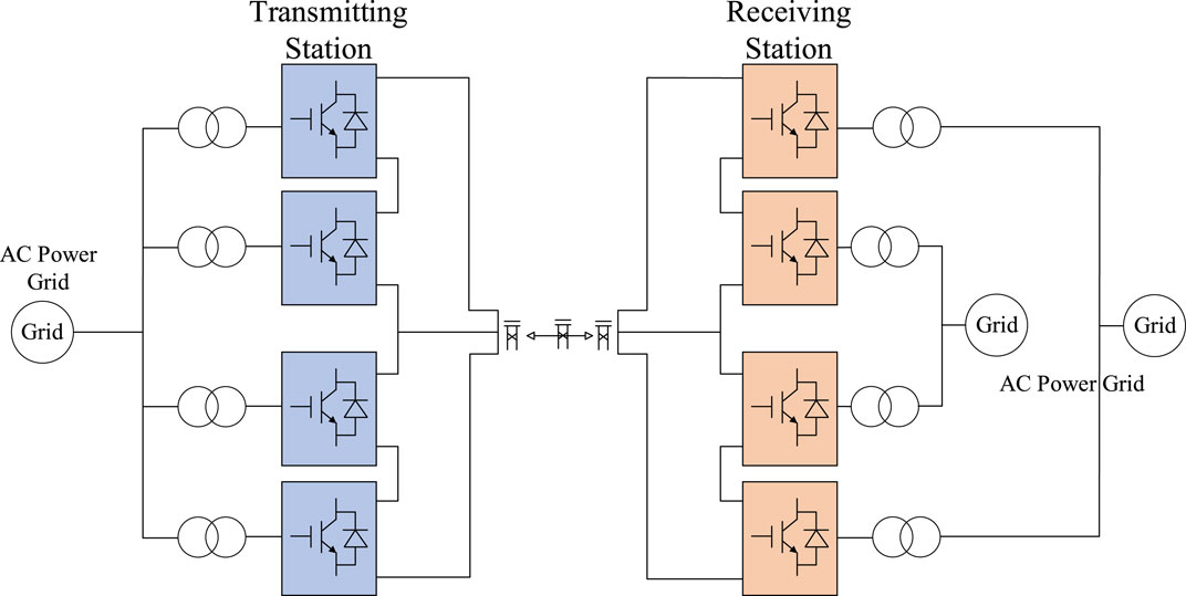
Figure 1. The topology of the dual ended MMC-UHVDC system.
For the MMC-UHVDC system, the stability of DC voltage is the foundation for power transmission, so it is necessary to have a converter station to control the DC voltage of the system, and the other converter stations to control the active power of the system.
Due to the consistent control strategies of the positive and negative electrode systems, the steady-state control strategy is analyzed using the positive electrode system as an example. The topology of the dual ended positive electrode system is shown in Figure 2, where the receiving station is called MMC1 and the transmitting station is called MMC2.
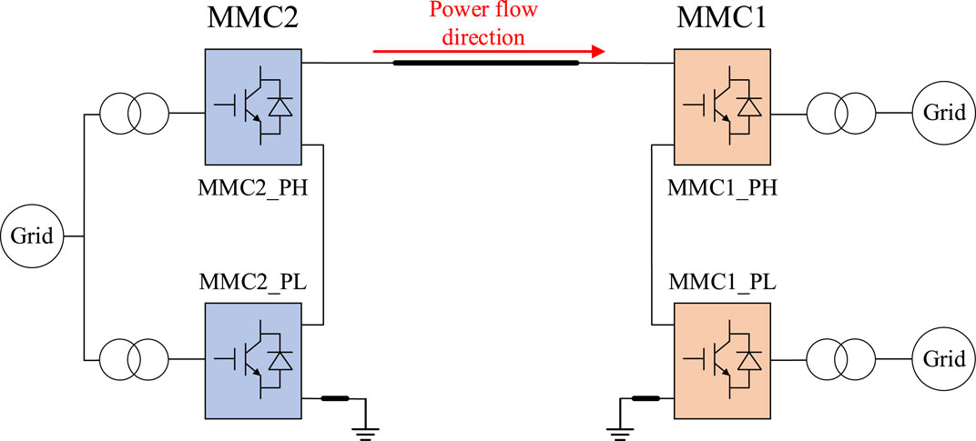
Figure 2. The topology of the positive electrode system.
For a dual ended DC transmission system, the transmission capacity is determined by the transmitting station, so the active power is generally controlled by the transmitting station and the DC voltage of the system is controlled by the receiving station.
In this control mode, the high MMC at receiving station (MMC1_PH) and low MMC at receiving station (MMC1_PL) control their own DC voltage to be stable, and the DC voltage of both MMC is controlled to the rated value Udc0, that is, Udc1_pH = Udc1_PL = Udc0. Due to the series structure of each MMC in the station, the DC current Idc of each MMC is equal, indicating that the DC input power of the 2 MMCs in the receiving station is equal. Because the power inside each MMC is balanced during steady state, the output AC power of MMC1_PH and MMC1_PL is also equal.
In the transmitting station, the high MMC at transmitting station (MMC2_PH) and low MMC at transmitting station (MMC2_PL) control their own AC active power, and the AC active power of the two MMC is equal. If there is no disturbance in the system, the DC voltage of both MMC will remain stable at the rated value Udc0. When a small disturbance occurs in the system, causing a small deviation △Udc in the DC voltage of the two MMC, if this disturbance causes the DC voltage Udc2_PH of MMC2_PH being higher than that of MMC2_PL, this relationship can be expressed as Eq. 1:
Then the DC side output power Pdc2_PH of MMC2_PH will increase, and the Pdc2_PH can be expressed as Eq. 2:
At this point, due to the constant input power Pac2_PH on the AC side of MMC2_PH, there will be a power imbalance phenomenon in the converter valve, the relationship can be expressed as Eq. 3:
There is a power loss phenomenon in MMC2_PH, which leads to a decrease in its DC voltage and gradually decreases to near the rated value Udc0.
Similarly, if the small disturbance in the system causes the DC voltage of MMC2_PH being lower than that of MMC2_PL, under the inherent relationship between the power and DC voltage of the MMC, the DC voltage of the MMC will also gradually recover to the rated value. Finally, the DC voltage of the MMC2_PH and MMC2_PL in the transmitting station will also be in an automatic equilibrium state, that is, Udc2_PH = Udc2_PL.
Based on the above analysis, when the transmitting station controls the active power of the system and the receiving station controls the DC voltage, the DC voltage and active power of the high and low converter valves in the receiving and transmitting stations can automatically maintain a balanced state in steady state.
This section mainly studies the system characteristics after a temporary AC power grid fault occurring. Considering that under the same type of fault conditions, the DC overvoltage caused by faults in the receiving station is the most severe. Therefore, this section takes the most severe three-phase metallic grounding fault (named ABCG fault) on the AC grid side of MMC1_PH in the receiving station as an example to analyze the system characteristics after the fault occurring. The schematic diagram of the positive electrode system fault is shown in Figure 3.
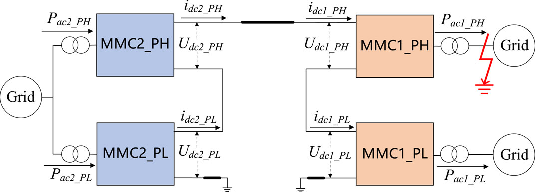
Figure 3. Schematic diagram of the system when the AC fault occurring in MMC1_PH.
For the receiving station, after the occurrence of ABCG fault, the amplitude of the three-phase voltage on the AC side of MMC1-PH drops to zero, so the output power of MMC1_PH on the AC side drops to zero. Meanwhile, due to the fact that the DC side of MMC1_PH can be seen as composed of the capacitors of MMC submodules in series and parallel. Therefore, MMC1_PH can be equivalent to a capacitor Ceq1_PH connected in series to the DC side of the system. For MMC1_PL in the receiving station, due to the hierarchical connection of MMC1_PL and faulty MMC1_PH to different AC power grids, so the AC active power output by MMC1_PL is not affected by the fault, and the DC voltage control capability of MMC1_PH remains unchanged. Therefore, MMC1_PL can be equivalent to a DC voltage power supply, with a voltage source amplitude of Udc1_PL.
For the transmitting station, both MMC2_PH and MMC2_PL maintain the control mode of controlling AC active power, and the active power of these 2 MMCs is equal, that is, Pac2_PH = Pac2_PL. According to the analysis in Section 2.2, it can be seen that the DC voltage of these 2 MMCs is also equal, that is, Udc2_PH = Udc2_PL. Therefore, the DC current of these 2 MMCs is also equal, with a current value of idc2_PH = idc2_PL. At the same time, the parameters of the MMC2_PH and MMC2_PL are exactly the same, so their DC side can be equivalent to equal capacitance. Therefore, the transmitting station can be equivalent to a controlled current source idc2 and an equivalent capacitor Ceq2 in parallel as a whole. The amplitude idc2 of the controlled current source is equal to the total active power Pac2 divided by the total DC voltage Udc2 at the transmitting station, and the equivalent capacitance Ceq2 is equal to the series value of the equivalent capacitance of MMC2_PH and MMC2_PL.
Based on the above analysis, the circuit of positive electrode system after the ABCG fault occurs on the AC grid side of MMC1_PH can be equivalent to the topology shown in Figure 4.
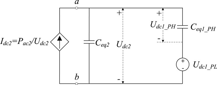
Figure 4. Equivalent circuit of positive electrode system after the ABCG fault occurs on MMC1_PH AC grid side.
Before the fault occurred, the DC voltage of MMC1_PH and MMC1_PL in the receiving station is equal. Therefore, in Figure 4, the initial voltage of the equivalent capacitance Ceq1_PH of MMC1_PH is equal to the equivalent DC voltage source amplitude Udc1_PL of MMC1_PL, both of which are rated values Udc0. Similarly, in Figure 4, the initial voltage of the equivalent capacitance Ceq2 in the transmitting station is Udc2 = 2*Udc0. Due to the fact that in the MMC-UHVDC system studied in this paper, the parameters of each MMC at the transmitting and receiving stations are equal, so the relationship between the equivalent capacitance Ceq1_PH and Ceq2 is: Ceq2 = Ceq1_PH/2.
Perform Laplace transform on the right circuit of port ab in Figure 4 to obtain the operational circuit shown in Figure 5A. Then using the Thevenin’s theorem, equivalent the circuit on the right side of port ab in Figure 5A to obtain the Thevenin equivalent circuit shown in Figure 5B. Finally, perform Laplace inverse transformation on the circuit in Figure 5B to obtain the time-domain circuit shown in Figure 5C, where the initial voltage of the equivalent capacitance of 1.5Ceq1_PH is Udc0.
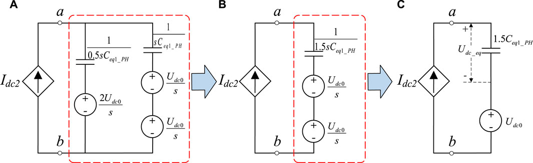
Figure 5. Further equivalent circuit after the ABCG fault occurs on MMC1_PH AC grid side. (A) Operational circuit (B) Thevenin equivalent circuit (C) Final equivalent circuit.
As shown in Figure 5C, the voltage of capacitor 1.5Ceq1_PH is Udc_eq, and the capacitor voltage can generally be equivalent to a historical voltage source and an equivalent resistance related to the capacitance value and calculation step (Gnanarathna et al., 2011). Therefore, Udc_eq can be expressed as Eq. 4:
In the above formula, △T is the calculation step size, and Udc_eq(t-△T) is the voltage of 1.5Ceq1_PH at the previous calculation time. idc2(t-△T) is the current flowing through the equivalent capacitor 1.5Ceq1_PH at the previous calculation time.
After the system completes the calculation of the capacitor voltage Udc_eq(t) at this time, the calculation result at this time is stored for the next calculation time.
The calculation formula for the current idc2(t+△T) flowing through the equivalent capacitor 1.5Ceq1_PH in the next calculation time of the system is:
By replacing the current idc2(t) in Eq. 4 with the calculated value idc2(t+△T) in Eq. 5, and the equivalent capacitor voltage Udc_eq(t+△T) at the next calculation time can be obtained. By iteratively calculating, the trend of the capacitor voltage Udc_eq(t) over time in the equivalent circuit of Figure 5C can be obtained.
The following text derives the voltage of the high-end and low-end MMCs in the transmitting and receiving stations based on the calculated voltage Udc_eq(t).
From Figures 4, 5C, it can be seen that the voltage at port ab is the total voltage Udc2 of the positive electrode system. Due to the fact that the DC voltage of MMC2_PH and MMC2_PL in the transmitting station is equal, the calculation formula for the DC voltage of these 2 MMCs is:
From Figure 4, it can be seen that for MMC1_PL in the receiving station, its DC voltage Udc1_PL is equal to Udc0. Therefore, the formula for calculating the DC voltage of MMC1_PH in the receiving station is shown in Eq. 7.
Figure 6 shows the trends of voltage variation over time for Udc1_PH(t), Udc1_PL(t), Udc2_PH(t), and Udc2_PL(t) after the fault occurring, with Ceq1_PH = 750uF, △T = 50us, Pac2 = 4000 MW, and Udc0 = 400 kV as the initial variables.
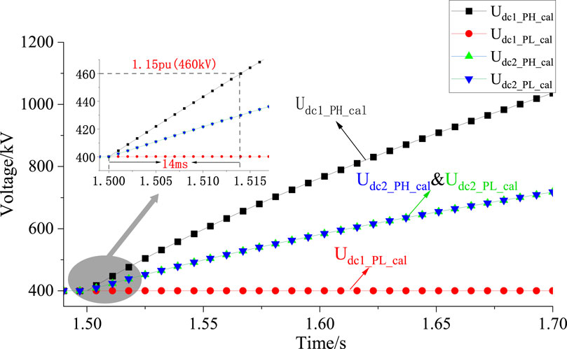
Figure 6. Calculation results of DC voltage variation trends for all MMCs after the fault.
From Figure 6, it can be seen that when a three-phase grounding fault occurs in the MMC1_PH of the receiving station, due to the system output power being blocked while the input power remains unchanged, the DC voltage of the system will rapidly increase. Among them, the DC voltage Udc1_PH(t) of the faulty MMC rises the fastest, and it rises to 1.15pu (460 kV) within 14 ms after the fault occurring. In order to avoid equipment damage caused by overvoltage in MMC, it is recommended that the system quickly take fault handling measures in a short period of time to protect the safety of the system equipment.
Section 3 has studied the system characteristics after an AC power grid fault occurring at the receiving station. The research results show that the DC voltage of the faulty MMC will rapidly increase, and the effective measure need to be taken in a timely manner to suppress overvoltage. Therefore, this section mainly studies the AC fault ride-through control strategy of the receiving station after the fault occurring.
In a dual ended MMC-UHVDC system, when an AC grid fault occurs in the MMC1_PH of the receiving station, so the output power on the AC side is blocked, resulting in surplus power in this MMC. The surplus power in the faulty MMC can be reduced by reducing the AC power of the transmitting station.
For the receiving station, during the fault ride through process, the control strategy of its high-end MMC and low-end MMC is the same, maintaining a constant DC voltage control strategy and adopting a current limiting control strategy to avoid serious overcurrent phenomena. The control strategy of MMC in the receiving station is shown in Figure 7.
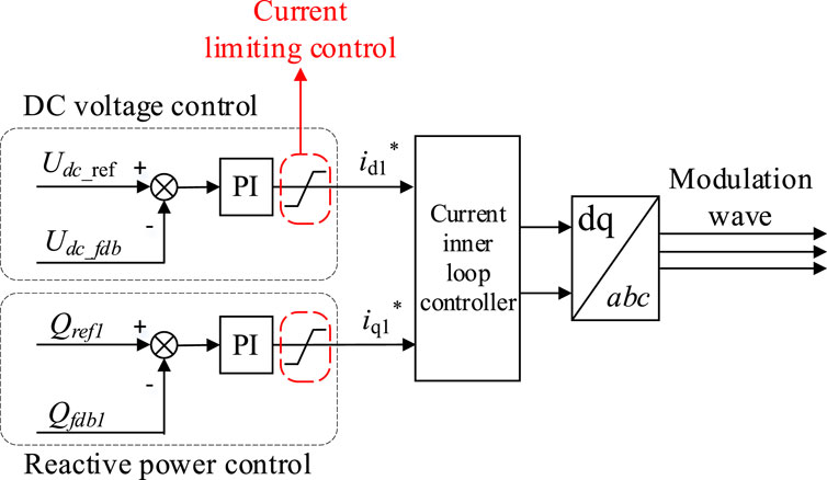
Figure 7. Basic control strategy of high-end MMC at the receiving station.
In Figure 7, Udc_ref is the DC voltage command value of MMC in the receiving station, and Udc_fdb is the DC voltage feedback value. Qref1 is the reactive power command value, and Qfdb1 is the reactive power feedback value; Id1* and Iq1* are the command values for the d-axis component and q-axis component of the current inner loop, respectively.
For the transmitting station, since the DC current of the high-end MMC and the low-end MMC are the same, and the DC voltage of the 2 MMCs are also in an automatic balancing state, so the AC power of the 2 MMCs must also be consistent. After the fault occurring, the active power of the high-end MMC and the low-end MMC need to be synchronously reduced. The control strategy for the MMCs in the transmitting station is consistent, as shown in Figure 8. When the transmitting station receives the fault signal, its MMCs synchronously reduce the active power command value, so that the active power absorbed by the MMC-UHVDC system from the AC power grid will be reduced, avoiding serious overvoltage in the system.
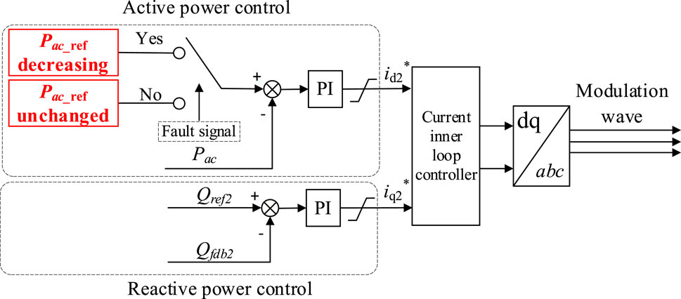
Figure 8. Basic control strategy of high-end MMC at the transmitting station.
In Figure 8, Pac_ref is the AC active power command value of MMC in the transmitting station, and Pac_fdb is the AC active power feedback value. Qref2 is the reactive power command value of MMC, and Qfdb2 is the reactive power feedback value. Id2* and Iq2* are the command values for the d-axis and q-axis components of the current inner loop of MMC, respectively.
When an ABCG fault occurs on the AC side of the high-end MMC in the receiving station, the active power output on the AC side of the MMC drops to zero. In order to ensure power balance of the faulty MMC, the DC current of the system should be reduced to zero. Under the control of the basic AC fault ride-through strategy, the active power of both the high-end MMC and low-end MMC in the transmitting station is reduced to zero. Meanwhile the active power of the low-end MMC in the receiving station that without fault is also reduced to zero due to the decrease in DC current.
According to the above analysis, there is certain problem when using the basic AC fault ride-through strategy. In order to reduce the surplus power in the faulty MMC, it is necessary to synchronously reduce the active power of all MMCs in the same pole to avoid serious overvoltage in the faulty MMC. So, it can be said that adopting this basic control strategy significantly reduces the power transmission capacity of the system during faults, leading to significant power shocks in the system.
Therefore, it is necessary to study the AC fault ride-through strategy with high power transmission capacity during the fault occurring.
In order to maximize the power transmission capacity of the system after a fault occurs, this paper proposes a strategy to reduce the surplus power in the faulty MMC by reducing its DC voltage while keeping the DC current of the system unchanged. At the same time, the transmitting station synchronously reduces a portion of active power. The following text provides a detailed explanation of the AC fault ride-through control strategy with high power transmission capability.
In MMC, electrical variables such as active power, DC voltage, and reactive power are controlled by adjusting the magnitude and phase of the bridge arm voltage. The expression of the a-phase bridge arm voltage in MMC is shown in Eq. 8 (Saeedifard and Iravani, 2010), and there is also the similar electrical variable relationship in b-phase and c-phase.
In the formula, varm_pa and varm_na are the voltages of the upper and lower bridge arms of a-phase in MMC, respectively; Udc is the DC voltage of MMC; ea is the voltage of phase A on the AC side of the MMC.
In the conventional basic control strategy of MMC, MMC is usually regarded as a single input control system as shown in Figure 9A, which only controls MMC by adjusting the valve side AC voltage eabc. In order to fully utilize the control freedom of MMC, MMC can be seen as a dual input control system as shown in Figure 9B, which can control the power balance in MMC by simultaneously adjusting the valve side AC voltage eabc and DC voltage Udc.
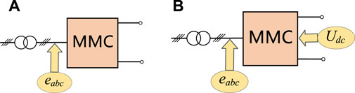
Figure 9. Equivalent control system of MMC. (A) Equivalent single input control system (B) Equivalent dual input control system.
When an AC fault occurs in the high-end MMC of the receiving station, the output active power on the AC side is blocked, and the AC side control ability of the faulty MMC is weakened. In order to quickly reduce the surplus power in the faulty MMC, the DC input power Pdc of the MMC can be reduced. And Pdc is directly related to the DC voltage Udc and DC current Idc, as shown in Eq. 9.
Due to the equal Idc of each MMC in the same pole system, in order to reduce the impact of faults on other MMCs without fault, it is chosen to reduce the surplus power by reducing the DC voltage Udc of the faulty MMC. The amount of surplus power in the faulty MMC will be reflected by the sub-module voltage. Therefore, a controller is designed between the submodule voltage and the DC voltage Udc. When the submodules’ average voltage vsm_ave increases and is higher than the rated value of the submodules’ average voltage vsm_rated in the faulty MMC, the DC modulation voltage Udc_m is decreased to reduce the input active power on the DC side, thereby controlling the power balance inside the faulty MMC. The control strategy on the AC side is the same as the basic strategy in Section 4.1, and the modulation voltage vabc on the AC side is obtained through dual closed-loop control. The overall control strategy of the faulty MMC is shown in Figure 10. The low-end MMC of the receiving station maintains the original control strategy unchanged.
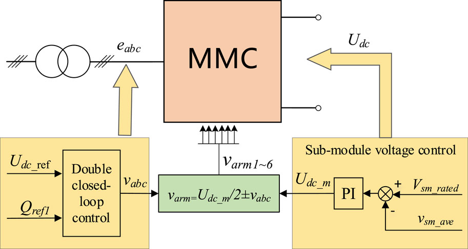
Figure 10. Control strategy of high-end MMC at the receiving station.
For the transmitting station, due to the fact that the input active power remains unchanged for a short period of time after the fault occurring, the system’s DC current will increase with the decrease of the receiving station’s DC voltage. In order to control the DC current near the rated value, a controller needs to be designed in the transmitting station between the DC current Idc_fdb and the active power reference value Pac_ref. Under the action of the controller, Pac_ref will decrease with the increase of Idc_fdb.
At the same time, in order to control the submodule voltage of the MMC in the transmitting station within a stable range, it is also necessary to control the DC voltage of the MMC. Therefore, a controller is designed between the submodules’ average voltage vsm_ave2 and the DC modulation voltage Udc_m2. Under the action of this controller, when vsm_ave2 decreases, Udc_m2 is decreased to reduce the output power on the DC side, thereby controlling the power balance within the MMC. Setting only one MMC as the power reducing MMC in the transmitting station can achieve the control goal. In this paper, the high-end MMC in the transmitting station is set to reduce active power. The control strategy of this MMC is shown in Figure 11, while the low-end MMC maintains the original control strategy.
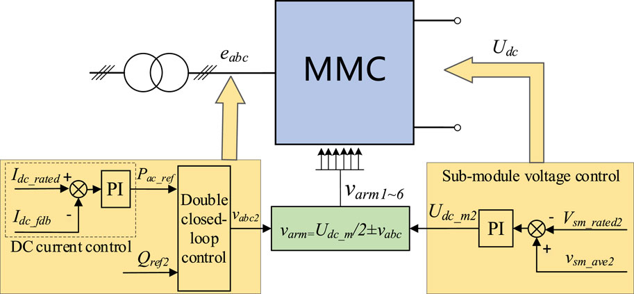
Figure 11. Control strategy of high-end MMC at the transmitting station.
To verify the effectiveness of the proposed AC fault ride-through strategy, a simulation model of the dual ended system is built based on the PSCAD/EMTDC simulation platform, as shown in Figure 1. The parameters of each MMC in the system are the same, and Table 1 provides the system parameters and the parameters of a single MMC.
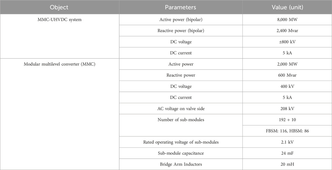
Table 1. Main parameters of the MMC-UHVDC transmission system.
This section takes the ABCG fault on the AC power grid side of the high-end MMC in the receiving station as an example, and analyzes the system fault characteristics without adopting fault ride-through strategy. As the parameters and control strategies of the positive and negative electrode systems are the same, only the simulation results of the positive electrode system are provided in this paper.
Set the fault to occur at 1.5 s, record the waveforms of the DC voltages Udc1_PH and Udc1_PL of MMC1_PH and MMC1_PL in the receiving station, as well as the waveforms of the DC voltages Udc2_PH and Udc2_PL of MMC2_PH and MMC2_PL in the transmitting station. The simulation results are shown in Figure 12. In this figure, data from the theoretical calculations in Section 3, including Udc1_PH_cal, Udc1_PL_cal, Udc2_PH_cal, and Udc2_PL_cal, were also added for comparison.
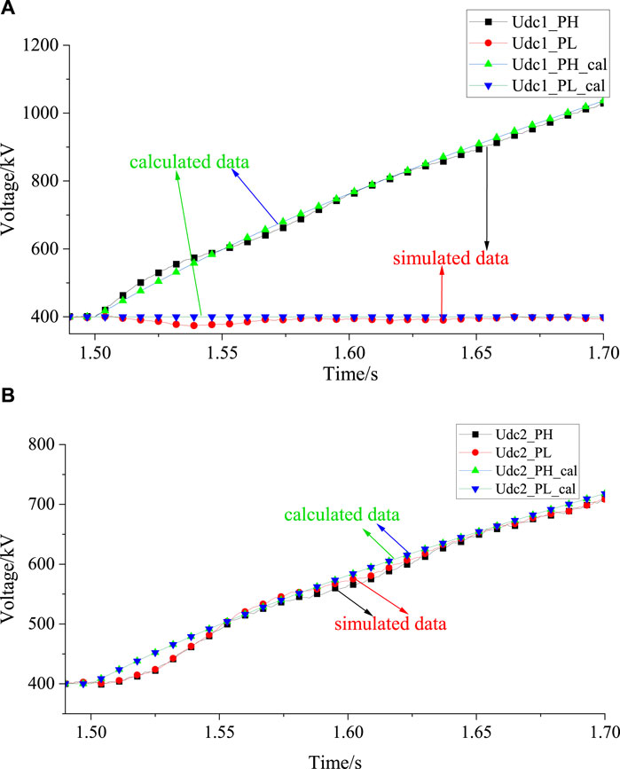
Figure 12. DC voltage after a three-phase ground fault occurs in MMC1_PH. (A) Calculation and simulation results of DC voltage for MMC1_PH and MMC1_PL (B) Calculation and simulation results of DC voltage for MMC2_PH and MMC2_PL.
From Figure 12, it can be seen that after the fault occurring, the DC voltage Udc1_PH of the faulty MMC1_PH rapidly increases, while the DC voltage Udc1_PL of MMC1_PL stabilizes around the rated value. For the transmitting station, the DC voltage of MMC2_PH and MMC2_PL increases synchronously, but the rising speed is lower than the DC voltage of the faulty MMC. The simulation results are consistent with the theoretical calculation results, verifying the correctness of the theoretical analysis results in Section 3.
This section analyzes the effectiveness of the fault ride-through control strategy proposed in Section 4.2 based on a dual end simulation model. The fault conditions are: single-phase ground fault and three-phase ground fault occur on the AC grid side of the high-end MMC in the receiving station. The fault time settings for the two types of faults are the same. The system runs in a stable state before 1.5 s, and the fault occurs between 1.5 s and 2.0 s. The fault is cleared after 2.0 s.
As the parameters and control strategies of the positive and negative electrode systems are the same, only the simulation results of the positive electrode system are provided in this paper. The variables of MMC1_PH and MMC1_PL in the receiving station were recorded, including DC voltage Udc1_PH and Udc1_PL, average voltage of all sub-modules vsm_ave1_PH and vsm_ave1_PL, AC side output active power Pac1_PH and Pac1_PL, as well as the DC current Idc of the system. For the transmitting station to record the variables of MMC1_PH and MMC2_PH, including DC voltage Udc2_PH and Udc2_PL, average voltage of all sub-modules vsm_ave2_PH and vsm_ave2_PL, AC side input active power Pac2_PH and Pac2_PL.
The simulation results of a single-phase ground fault occurring on the AC grid side of MMC1_PH in the receiving station are shown in Figures 13, 14.
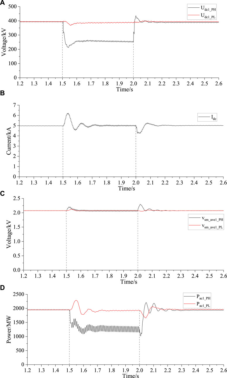
Figure 13. Simulation waveforms of receiving station during single-phase ground fault. (A) DC voltage of MMC1_PH and MMC1_PL (B) DC current of the system (C) Average voltage of submodules of MMC1_PH and MMC1_PL (D) AC side active power of MMC1_PH and MMC1_PL.
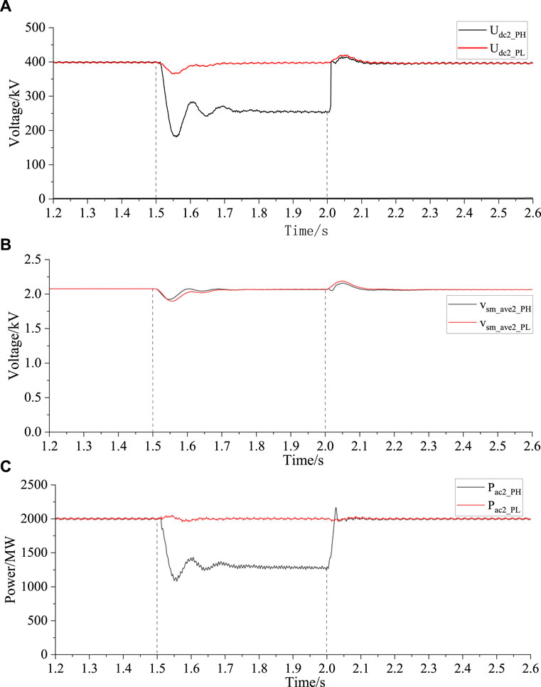
Figure 14. Simulation waveforms of transmitting station during single-phase ground fault. (A) DC voltage of MMC2_PH and MMC2_PL (B) Average voltage of submodules of MMC2_PH and MMC2_PL (C) AC side active power of MMC2_PH and MMC2_PL.
As can be seen from Figure 13D, after the fault occurring, the output active power Pac1_PH of MMC1_PH rapidly decreased to around 1,300 MW. Due to the obstruction of the active power output of MMC1_PH, there will be surplus power in the MMC shortly after the fault occurring, resulting in an increase in the voltage of its submodule vsm_ave1_PH, as shown in Figure 13C. As shown in Figures 13A, B, when the system detects the fault, it begins to execute the fault ride-through strategy, and the DC voltage of MMC1_PH is controlled to decrease to around 250 kV. The decrease in DC voltage of the system leads to the increase in DC current Idc of the system.
For the transmitting station, as shown in Figure 14C, in order to control the system DC current near the rated value, under the action of the AC fault ride-through strategy, the input active power of the MMC2_PH is reduced to about 1,300 MW. At the same time, in order to stabilize the voltage of the sub-module near the rated value, MMC2_PH controls its DC voltage Udc2_PH to decrease with the decrease of the voltage of the sub-module vsm_ave2_PH. After the fault enters steady state, Udc2_PH drops to about 250 kV, as shown in Figures 14A, B.
During the entire fault process, the active power and DC voltage of the high-end MMC in the receiving and transmitting stations decrease synchronously, which can stably control the DC current of the system near the rated value. The AC active power, DC voltage, and sub-module voltage of all MMCs in the system are controlled within a stable range, and there is no serious overvoltage or overcurrent phenomenon in the system. Based on the above analysis, it can be concluded that after the single-phase ground fault occurs in MMC1_PH, the system can still retain about 83% of its power transmission capacity, which verifies the effectiveness of the AC fault ride-through strategy proposed in this paper.
The simulation results of a three-phase ground fault occurring on the AC grid side of MMC1_PH in the receiving station are shown in Figures 15, 16.
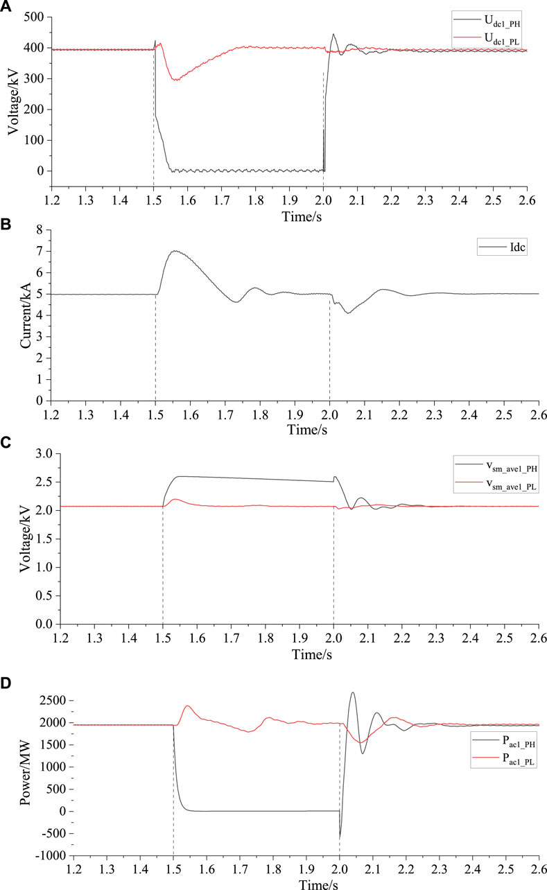
Figure 15. Simulation waveforms of receiving station during three-phase ground fault. (A) DC voltage of MMC1_PH and MMC1_PL (B) DC current of the system (C) Average voltage of submodules of MMC1_PH and MMC1_PL (D) AC side active power of MMC1_PH and MMC1_PL.
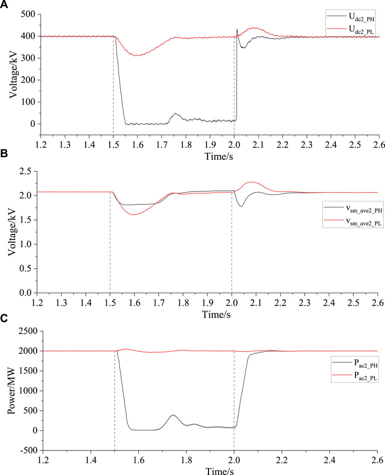
Figure 16. Simulation waveforms of transmitting station during three-phase ground fault. (A) DC voltage of MMC2_PH and MMC2_PL (B) Average voltage of submodules of MMC2_PH and MMC2_PL (C) AC side active power of MMC2_PH and MMC2_PL.
As can be seen from Figure 15D, after the fault occurring, the output active power Pac1_PH of MMC1_PH rapidly decreased to 0 MW. In the short period after the fault occurring, there will be a large amount of surplus power in this MMC, resulting in an increase in the voltage of its submodule vsm_ave1_PH, as shown in Figure 15C. As shown in Figures 15A, B, when the system detects the fault, it begins to execute the fault ride-through strategy, and the DC voltage of MMC1_PH is controlled to decrease to around 0 kV. The decrease in DC voltage of the system leads to the increase in DC current Idc of the system.
For the transmitting station, as shown in Figure 16C, in order to control the system DC current near the rated value, under the action of the AC fault ride-through strategy, the input active power of the MMC2_PH is reduced to 0 MW. At the same time, in order to stabilize its voltage of the sub-module near the rated value, MMC2_PH controls its DC voltage Udc2_PH to decrease with the decrease of the voltage of the sub-module vsm_ave2_PH. After the fault enters steady state, Udc2_PH drops to about 0 kV, as shown in Figures 16A, B.
During the entire fault process, the active power and DC voltage of the high-end MMC in the receiving and transmitting stations synchronously decreased to zero, which can stably control the DC current of the system near the rated value. The AC active power, DC voltage, and sub-module voltage of all MMCs in the system are controlled within a stable range, and there is no serious overvoltage or overcurrent phenomenon in the system. Based on the above analysis, it can be concluded that after the three-phase ground fault occurs in MMC1_PH, the system can still retain about 50% of its power transmission capacity, which verifies the effectiveness of the AC fault ride-through strategy proposed in this paper.
Addressing the current absence of an AC fault ride-through control strategy with robust power transmission capabilities for the MMC-UHVDC system with hierarchical connection mode, this paper first analyzes the characteristics of the system when a fault occurs in the AC power grid. Subsequently, it introduces an innovative AC fault ride-through control strategy with high power transmission capability. Finally, conduct simulation analysis on the proposed strategy. The conclusions are as follows:
(1) Based on theoretical analysis, this paper obtains the equivalent circuit of the high-end MMC in the receiving station after a three-phase ground fault occurring on the AC power grid side, and uses theoretical calculation methods to obtain the trend of DC voltage changes of the all MMCs in the transmitting station and receiving station after the fault occurring. According to the calculation results, it can be concluded that the DC voltage of the faulty MMC rises the fastest, and it rises to 1.15pu (i.e. 460 kV) within 14 ms after the fault occurring. And the simulation results have verified the correctness of the theoretical analysis. To protect the safety of system equipment, it is recommended that the system quickly take fault handling measures in a short period of time after a fault occuring.
(2) An AC fault ride-through control strategy with high power transmission capability has been proposed based on the characteristics of the system. The implementation of this control strategy requires coordination and cooperation between the transmitting station’s MMC and the receiving station’s MMC. In order to maintain the stability of the system’s DC current, this strategy requires synchronous reduction of the DC voltage of the faulty MMC and the partial active power of the transmitting station, so as to reduce the impact of system fault ride-through strategy on MMC that has not experienced faults. This strategy can maximize the retention of the system’s power transmission capacity during failures and reduce power shock in the system.
(3) Based on the PSCAD simulation platform, simulate the fault conditions of single-phase ground fault and three-phase ground fault in the high-end MMC at the receiving station. The simulation results show that when a single-phase ground fault occurs, the system can still maintain about 83% of its power transmission capacity during the fault period. When a three-phase grounding fault occurs, the system can maintain approximately 50% of its power transmission capacity during the fault period. The simulation results have verified the effectiveness of the proposed AC fault ride-through control strategy.
The original contributions presented in the study are included in the article/Supplementary Material, further inquiries can be directed to the corresponding author.
MP: Conceptualization, Data curation, Formal Analysis, Investigation, Methodology, Project administration, Resources, Software, Supervision, Validation, Writing–original draft, Writing–review and editing. CN: Conceptualization, Formal Analysis, Methodology, Writing–review and editing. XL: Conceptualization, Methodology, Writing–review and editing. MY: Software, Supervision, Validation, Writing–review and editing. XW: Software, Validation, Writing–review and editing.
The author(s) declare that financial support was received for the research, authorship, and/or publication of this article. This research work was supported by the China Electrical Equipment Science and Technology Project (CEE-2023-B-01-01-013-XJ).
Authors MP and XL were employed by XJ Electric Corporation.
Authors MP, CN, and MY were employed by Xi’an Xuji Power Electronics Technology Co., Ltd.
Author XW was employed by China Electrical Equipment Group Co., Ltd.
All claims expressed in this article are solely those of the authors and do not necessarily represent those of their affiliated organizations, or those of the publisher, the editors and the reviewers. Any product that may be evaluated in this article, or claim that may be made by its manufacturer, is not guaranteed or endorsed by the publisher.
Alghamdi, O. A., Alhussainy, A. A., Alghamdi, S., AboRas, K. M., Rawa, M., Abusorrah, A. M., et al. (2023). Optimal techno-economic-environmental study of using renewable energy resources for Yanbu city. Front. Energy Res. 10. doi:10.3389/fenrg.2022.1115376
Baoan, X., Mingqun, G., Shaowu, W., et al. (2021). Friendly HVDC transmission Technologies for large-scale renewable energy and their engineering practice [J]. Automation Electr. Power Syst. 45 (22), 1–8. (In Chinese). doi:10.7500/AEPS20210302001
Boning, Y., Tianxin, Z., Ming, D., and Ming, R. (2020). “Simulation research on operation characteristics of AC energy consuming device in VSC-HVDC system,” in The 16th IET international conference on AC and DC power transmission (ACDC 2020), Online Conference, July 02–03, 2020 (IET), 2315–2318.
Ding, Y., Wang, F., Wang, W., Wang, G., Xiong, J., and Fu, J. (2020). “Analysis of DC line fault characteristics with the UHVDC hierarchical integration into AC power grid,” in 2020 5th asia conference on power and electrical engineering, Chengdu, China, June 04–07, 2020 (IEEE), 1539–1543.
Fu, F., Pan, H., and Jia, X. (2022). “A hybrid MMC with low FBSM ratio for DC fault,” in 2022 4th international conference on power and energy technology (ICPET), Beijing, China, July 28–31, 2022 (IEEE), 456–461.
Gnanarathna, U. N., Gole, A. M., and Jayasinghe, R. P. (2011). Efficient modeling of modular multilevel HVDC converters (MMC) on electromagnetic transient simulation programs. IEEE Trans. Power Deliv. 26 (1), 316–324. doi:10.1109/TPWRD.2010.2060737
Han, Y., Wang, Q., Liu, P., Peng, Z., and Tong, X. (2023). “Research on DC fault clearance speed of hybrid MMC full bridge submodule ratio,” in 2023 2nd international conference on power systems and electrical technology (PSET), Milan, Italy, Auguest 25–27, 2023, 18–22.
Jia, N., Qi, W., Yi, T., and Chen, B. (2016). “Study on the characteristics of AC/DC hybrid system under UHVDC hierarchical connection mode,” in 2016 IEEE PES asia-pacific power and energy engineering conference (APPEEC), Xi’an, China, October 25–28, 2016 (IEEE), 1013–1017.
Lei, Y., He, X., Duan, J., and Li, H. (2019). “Boundary protection scheme for HVDC transmission system,” in 2019 IEEE 8th international conference on advanced power system automation and protection (APAP), Xi’an, China, October 21–24, 2019 (IEEE), 75–79.
Li, X., Pu, Y., Ma, Y., Xiong, L., and Guo, Q. (2017). “DC voltage balance control of UHVDC system with hierarchical connection mode,” in IECON 2017 - 43rd Annual Conference of the IEEE Industrial Electronics Society, Beijing, China, October 29–November 01, 2017 (IEEE), 3003–3008.
Liu, W., Fan, W., Hong, Y., and Chen, C. (2021). A study on the comprehensive evaluation and analysis of China’s renewable energy development and regional energy development. Front. Energy Res. 9. doi:10.3389/fenrg.2021.635570
Ma, H., Ping, M., Li, D., Yang, M., Liu, X., and Zhou, Y. (2020). “Optimized AC Fault Ride-through strategy for back-to-back VSC-HVDC system,” in 2020 IEEE 4th conference on energy internet and energy system integration (EI2), Wuhan, China, October 30–November 01, 2020 (IEEE), 794–799.
Nentwig, C., Haubrock, J., Renner, R. H., and Van Hertem, D. (2016). “Application of DC choppers in HVDC grids,” in 2016 IEEE international energy conference (ENERGYCON), Leuven, Belgium, April 04–08, 2016 (IEEE), 1–5.
Nian, M., Yang, Z., Tan, L., and Bian, Y. (2020). Energy consumption method for power surplus in zhangbei VSC-based DC grid. Power Syst. Technol. 44 (05), 1991–1999. (In Chinese). doi:10.13335/j.1000-3673.pst.2019.1946
Qi, W., Jun, Y., Lei, W., Tiezhu, W., Lingkuan, W., and Yucheng, G. (2018). “Study on operation characteristics of UHVDC power system with hierarchical connection to AC grid,” in 2018 international conference on power system technology (POWERCON), Guangzhou, China, November 6–8, 2018, 3158–3165.
Rokicki, T., Koszela, G., Ochnio, L. B., Perkowska, A., Bórawski, P., Bełdycka-Bórawska, A., et al. (2022). Changes in the production of energy from renewable sources in the countries of Central and Eastern Europe. Front. Energy Res. 10. doi:10.3389/fenrg.2022.993547
Saadeh, O., Sba, B. A., Dalala, Z., and Bashaireh, A. (2023). “Comparative performance analysis of HVDC and HVAC transmission systems in the presence of PV generation: a case study using the IEEE-5-bus network,” in 2023 AEIT HVDC international conference (AEIT HVDC), Rome, Italy, May 25–26, 2023 (IEEE), 1–5.
Saeedifard, M., and Iravani, R. (2010). Dynamic performance of a modular multilevel back-to-back HVDC system. IEEE Trans. Power Deliv. 25 (4), 2903–2912. doi:10.1109/TPWRD.2010.2050787
Sixuan, X., Feifei, Z., Guojing, L., Quanquan, W., and Lu, W. (2023). “Fault ride-through strategy of new energy through flexible DC based on wind power shedding and energy consumption device,” in 2023 2nd asian conference on frontiers of power and energy (ACFPE), Chengdu, China, October 20–22, 2023, 706–710.
Vercellotti, U. (2019). “HVDC links at increased voltage, CESI experience on extruded cable systems up to 525kV,” in 2019 AEIT HVDC international conference (AEIT HVDC), Florence, Italy, May 9–10, 2019, 1–5.
Wang, D., and Li, Q. (2023). “Research on cooperative Fault Ride-through strategy of offshore wind power grid-connected system via VSC-HVDC system,” in 2023 international conference on power energy systems and applications (ICoPESA), Nanjing, China, February 24–26, 2023, 96–103.
Wang, H., and Redfern, M. A. (2010). “The advantages and disadvantages of using HVDC to interconnect AC networks,” in 45th international universities power engineering conference UPEC2010, Cardiff, Wales, 1–5.
Xiong, L., Liu, X., Zhang, D., and Liu, Y. (2021). Rapid power compensation-based frequency response strategy for low-inertia power systems. IEEE J. Emerg. Sel. Top. Power Electron. 9 (4), 4500–4513. doi:10.1109/jestpe.2020.3032063
Xu, B., Wang, X., Wang, G., Ning, Z., Li, J., and Zhou, J. (2021). “The state of art of energy consumption devices for offshore wind power system,” in 2021 international conference on power system technology (POWERCON), Haikou, China, December 08–09, 2021 (IEEE), 1510–1514.
Ying, P., Lingfei, X., Xun, G., Yajun, L., Qidi, Z., Jian, Y., et al. (2018). “Study on control strategies for UHVDC system with 500kV/1000kV AC hierarchical connection at receiving end,” in 2018 international conference on power system technology (POWERCON), Guangzhou, China, November 6–8, 2018, 2306–2312.
Keywords: MMC-UHVDC, hierarchical connection mode, AC fault ride-through, reducing DC voltage, high power transmission capability
Citation: Ping M, Niu C, Liu X, Yang M and Wang X (2024) AC fault ride-through control strategy of MMC-UHVDC system with hierarchical connection mode. Front. Energy Res. 12:1426902. doi: 10.3389/fenrg.2024.1426902
Received: 02 May 2024; Accepted: 03 July 2024;
Published: 24 July 2024.
Edited by:
Haitao Zhang, Xi’an Jiaotong University, ChinaReviewed by:
Xingxing Chen, Hong Kong Polytechnic University, Hong Kong SAR, ChinaCopyright © 2024 Ping, Niu, Liu, Yang and Wang. This is an open-access article distributed under the terms of the Creative Commons Attribution License (CC BY). The use, distribution or reproduction in other forums is permitted, provided the original author(s) and the copyright owner(s) are credited and that the original publication in this journal is cited, in accordance with accepted academic practice. No use, distribution or reproduction is permitted which does not comply with these terms.
*Correspondence: Mingli Ping, bWwxMjMyMDExQDE2My5jb20=
Disclaimer: All claims expressed in this article are solely those of the authors and do not necessarily represent those of their affiliated organizations, or those of the publisher, the editors and the reviewers. Any product that may be evaluated in this article or claim that may be made by its manufacturer is not guaranteed or endorsed by the publisher.
Research integrity at Frontiers
Learn more about the work of our research integrity team to safeguard the quality of each article we publish.