 Lin Chai
 Qiang Sun1
95% of researchers rate our articles as excellent or good
Learn more about the work of our research integrity team to safeguard the quality of each article we publish.
Find out more
ORIGINAL RESEARCH article
Front. Energy Res. , 11 July 2024
Sec. Process and Energy Systems Engineering
Volume 12 - 2024 | https://doi.org/10.3389/fenrg.2024.1426840
As a novel technology, the mechanical stable platform can effectively improve the temperature resistance of the automatic vertical drilling system, but its working characteristics are still not yet clear. In this paper, theoretical mechanics is introduced to establish the critical deviation angle model, in order to evaluate the sensitivity of the mechanical stable platform to well deviation. Multi-body dynamics simulation is applied to mutually verify the models and further analyze the effect of vibration. The results show that the critical deviation angle is not only affected by the platform design parameters, but also by the system speed and external vibration. When the system angular velocity is less than the critical angular velocity
The main difference between the Mechanical Vertical Drilling System (MVDS) and the Electric Control Vertical Drilling System (EVDS) is that MVDS uses a mechanical stable platform to monitor the well deviation, without the use of any electronic components. MVDS has several advantages over EVDS. It can be used in high-temperature deep wells where EVDS is not suitable, and it can also reduce manufacturing and maintenance costs. However, MVDS also has its drawbacks. The sensitivity of the mechanical stable platform to well deviation is significantly lower compared to the high-precision sensors used in EVDS, due to factors such as tool size, friction between components, and external environmental conditions (Bram et al., 1988; Oppelt et al., 1991; Chur and Oppelt, 1993; Claus et al., 1995; Ma et al., 2016).
As the “brain” of the MVDS, the mechanical stable platform is a crucial component. It utilizes the eccentric block as the sensing element. Ideally, when the well deviation occurs, the eccentric block will deflect towards the lower side of the borehole under the effect of gravity. However, the characteristic of the eccentric block is that it does not generate any eccentric moment when it is at the lower side of the borehole, which means that it lacks the ability to maintain stability. Therefore, when it is affected by factors such as internal component friction or external vibration, it can deviate from the lower side of the borehole and oscillate, causing instability or even rotation, thus affecting the sensitivity of the mechanical stable platform (Reich et al., 2003; Lin et al., 2020a; Lin et al., 2020b).
As a novel technology, there has been relatively limited research and development on the mechanical stable platform. The first MVDS worldwide was developed by Halliburton, called the V-Pilot. Since then, Scout Downhole and Sinopec have also developed their own MVDS. However, due to commercial confidentiality, there have been little reports on the internal structure and performance of their mechanical stable platforms (Comeaux et al., 2007; Laiju et al., 2008; Jones et al., 2016; Li et al., 2017). Meanwhile, scholars from universities have conducted research on mechanical stable platforms to some extent. Li et al. derived the stable position model of the eccentric block based on the static balance principle and investigated its dynamic characteristics under the effect of torsional vibration (Li et al., 2018). Wang et al. analyzed the effects of various design parameters on the stable position based on the stable position model and conducted experimental testing and analysis on the plate valves friction co-efficient (Wang et al., 2020b; Wang et al., 2021). Li et al. further analyzed the influence of various design parameters on the stable time of the eccentric block (Ranran et al., 2022). Zhang et al. optimized the structure of plate valves based on the stable position model and proposed a solution to reduce friction using the convex-faced plate valves (Wang et al., 2020a). In order to mitigate the frictional effects of the plate valves on the eccentric block, Liu et al. designed a hydraulic balanced turbine based on error compensation principles (Ma et al., 2023). Li et al. constructed a non-contact angular position measurement method for the eccentric block using an absolute magnetic encoder.
In summary, most of the researches done by scholars so far are based on the analysis and optimization of the stable position model of the eccentric block. However, the following problems still exist.
1. The stable position model of the eccentric block is derived based on statics, which means that it ignores the intermediate process from the initial state to the final stable state of the eccentric block. At the same time, due to the neglect of the inertia and acceleration of the eccentric block, in some cases, the calculated stable position may not exist in actual working conditions. Therefore, the analysis and optimization based on the stable position model also lack practical significance.
2. Currently, the research on mechanical stable platform mainly focuses on the analysis and optimization in ideal environments, considering only the influence of internal structural parameters. As a result, there is a lack of comprehensive studies that consider external disturbances, especially the effects of system rotation speed and external vibrations on the well deviation sensitivity of the mechanical stable platform.
To solve these problems, on the basis of the stable position model of the eccentric block, this paper derives the well deviation sensitivity model of the mechanical stable platform, namely, the critical deviation angle model, based on the kinetic energy theorem. This model is then utilized to analyze the sensitivity of various design parameters of the stable platform. Furthermore, the paper constructs a universal dynamic equation for the eccentric block of the mechanical stable platform through theoretical analysis. The inherent motion characteristics of the eccentric block are analyzed using this equation. Additionally, a multi-body dynamic model of the mechanical stable platform is established. Bidirectional approximation method is used to verify the simulation model against the theoretical model, and the effect of torsional vibration, axial vibration, and torsional-axial coupled vibration on the critical deviation angle are further investigated. This paper aims to provide designers with a better understanding of the deviation response characteristics of mechanical stable platforms in complex downhole environments, and offer insights for structural optimization of the system.
Before conducting force analysis on a mechanical stable platform, it is necessary to understand its working principle. Figure 1A is the schematic diagram of the mechanical stable platform, which mainly includes four parts: an eccentric block, an upper plate valve, a lower plate valve, and bearings. When the system is working underground, the lower plate valve rotates synchronously with the shell and bit, The upper plate valve is fixed with the eccentric block circumferentially through the connecting key. The eccentric block is isolated from the shell by the bearing so that it can rotate freely around the tool center. When well deviation occurs, the eccentric block drives the upper plate valve to rotate to the lower side of the borehole under the effect of gravity. Therefore, the arc hole on the upper plate valve, which is opposite the eccentric block, can be located at the upper side of the borehole. When one of the flow channels on the lower plate valve rotates to the upper side of the borehole, it will be connected with the arc hole. At this moment, the high-pressure drilling fluid will flow in the connected channel and impel the corresponding steering rib of the actuator to push against the upper side of the wellbore, so as to make the bit produce side cutting force for deviation correction.
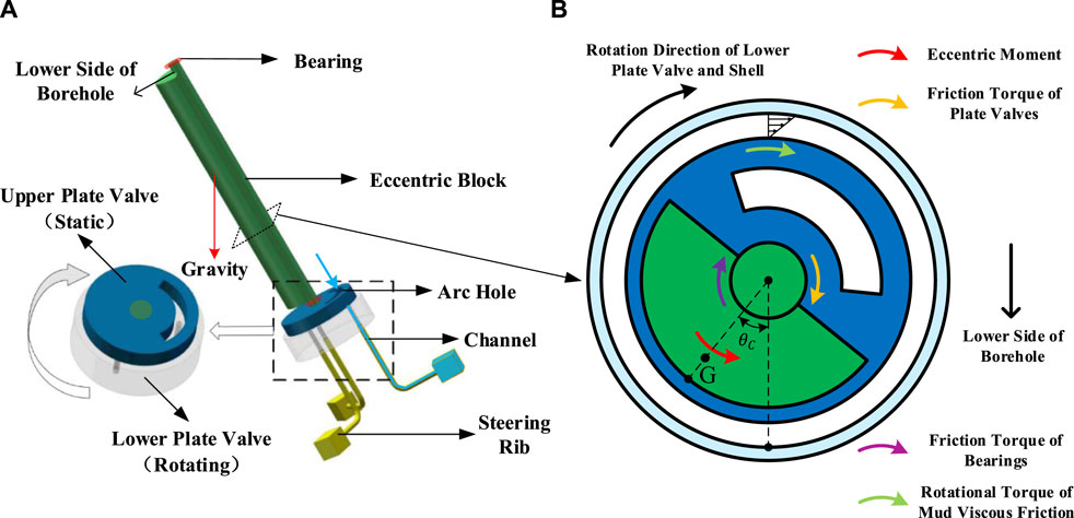
Figure 1. Schematic diagram and force analysis of mechanical stable platform: (A) schematic diagram; (B) force analysis.
According to the working principle of the mechanical stable platform, its key components are mutually fixed eccentric block and the upper plate valve, as their positions directly affect the direction of the pushing force used for deviation correction. Therefore, force analysis for them is particularly important. As shown in Figure 1B, the eccentric block and the upper plate valve are mainly subjected to four torques: the eccentric moment generated by the gravity of the eccentric block, the friction torque generated by the rotation of the lower plate valve, the friction torque of the bearing, and the viscous friction torque generated by the mud between the eccentric block and the shell. Among them, the eccentric moment is the active torque, and each friction torque is the interference torque. The two together determine the stable position of the eccentric block and the upper plate valve. When the eccentric block stabilizes at a certain position, the angle between the centerline of the eccentric block and the lower side of the borehole is defined as the critical deflection angle
1. Treat the components of the stable platform as rigid bodies.
2. No consideration of external vibrations.
When the active torque is equal to the interference torque, the eccentric block will stop at the critical deflection angle position. Therefore, in order to calculate the critical deflection angle, it is necessary to establish mechanical models for the active torque and interference torque separately.
When the cross-section of the eccentric block is designed as semi-circular, it can generate the maximum eccentric moment, and the calculation formula is shown in Eq. 1 (Chai et al., 2021).
wherein,
The upper and lower plate valves of MVDS are usually designed to be circular, and the friction torque of the plate valves can be obtained by integral method after ignoring the influence of the holes on the upper and lower plate valves (Li, 2018).
wherein,
The eccentric block is connected to the shell through radial ball bearings. When the shell rotates, the bearing friction torque generated is shown in Eq. 3.
wherein,
During the drilling process, due to the rotation of the shell with the bit, the mud in the annulus between the shell and the eccentric block is driven to rotate. The viscous friction torque generated by the rotating mud on the stationary eccentric block is shown in Eq. 4 (Dongxia et al., 2000).
wherein,
The values of friction torque of bearings and viscous friction torque of mud are relatively small compared to eccentric moment and friction torque between plate valves, and are not on the same order of magnitude, so they are ignored. The calculation formula for the critical deflection angle can be obtained by combining Equation 1 and 2, as shown in Eq. 5.
The essence of the critical deflection angle is the stable position of the eccentric block, which can be used as an evaluation index for the deviation correction efficiency of the MVDS. According to the working principle of the mechanical stable platform, the smaller the value of the critical deflection angle, the greater the pushing force allocated to the upper side of the wellbore, and the higher the deviation correction efficiency. However, as the model is based on static, the effect of the inertia and acceleration of the eccentric block is ignored.
According to Eq. 5, when the design parameters and drilling process parameters are determined, the critical deflection angle is only related to the well deviation angle. By assigning typical values to Equation 5, it was found that the critical deflection angle is negatively correlated with the deviation angle (as shown in Figure 2). When the deviation angle of the well is 5.1°, the critical deflection angle is 90°. According to Eq. 1, it can be inferred that the eccentric block can generate the maximum eccentric moment under this deviation condition. When the deviation angle of the well is less than 5.1°, Eq. (5) has no real solution, indicating that the maximum eccentric moment generated by the eccentric block under this deviation condition still cannot balance the friction torque of the plate valves, and the eccentric block cannot stop at a certain position. Previous scholars used the deviation angle value corresponding to the critical deflection angle of 90° as the theoretical deviation sensitivity of the mechanical stable platform. The calculation formula is Eq. 6. However, due to the effect of inertia, the above situation is impossible in reality.
wherein,
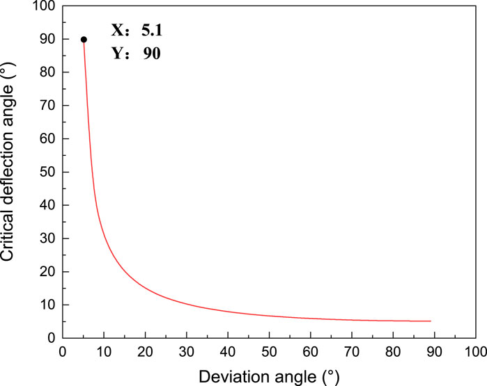
Figure 2. The relationship between critical deflection angle and well deviation angle.
In order to facilitate the analysis, the circular coordinate system is established clockwise, with the lower side of the borehole as the zero point. The coordinate system can represent the position of the centroid relative to the lower side of the borehole when the eccentric block rotates clockwise, namely, the deflection angle of the eccentric block. Since it is necessary to turn off the mud pump and stop the rotation of the drilling tool every time when connecting the MVDS or drill pipes, the pressure between the upper and lower plate valves is much smaller than when the pump is opened. Therefore, the eccentric block will fall to the lower side of the borehole due to the action of gravity, and the initial position and initial angular velocity of the eccentric block in the downhole are both 0. After opening the pump for circulation and rotary drilling, the eccentric block starts to move clockwise under the influence of plate valve friction torque.
The relationship curve shown in Figure 3A can be obtained from Eqs 1, 2, with the vertical axis representing the resultant moment received by the eccentric block (the difference between the eccentric moment and the friction torque of the plate valves), and the horizontal axis representing the deflection angle of the eccentric block. When the value of resultant moment is positive, the eccentric moment is greater than the friction torque, and the eccentric block decelerates. When the value of resultant moment is negative, the eccentric moment is smaller than the friction torque, and the eccentric block accelerates.
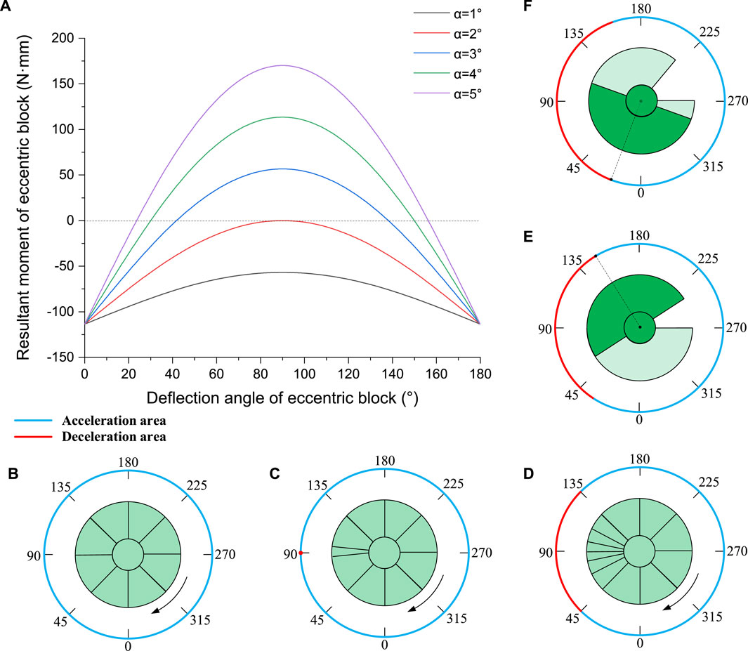
Figure 3. Movement diagram of eccentric block: (A) the relationship between resultant moment and deflection angle of eccentric block; (B) first state; (C) second state; (D) third state; (E) fourth state; (F) fifth state.
It can be seen from Figure 3A that under different well deviation angles the shape of the relation curve is parabola, and the parabola is symmetrical with respect to the straight line (x = 90°). The abscissa value of the intersection point of parabola and dashed line is the critical deflection angle of the eccentric block. With the decrease of well deviation angle, the parabola gradually flattens. According to the characteristics of parabolas, they can be divided into five states.
1. When the deviation angle is small, the eccentric moment of the eccentric block is always less than the friction torque of the plate valves, and there is no intersection point between the parabola and the dashed line (as shown by the black line in Figure 3A). At this time, the real solution of the critical deflection angle cannot be obtained by Eq. 5. There is no deceleration area in the circumferential direction, and the eccentric block will rotate clockwise in one direction (as shown in Figure 3B).
2. When the deviation angle increases to a certain value, the maximum eccentric moment of the eccentric block is equal to the friction torque of the plate valves. There is an intersection point between the parabola and the dashed line (as shown by the red line in Figure 3A), and the abscissa value of the intersection point (θ = 90°) is the critical deflection angle of the eccentric block under this well deviation of
3. When the well deviation continues to increase, the eccentric moment of the eccentric block will be greater than the friction torque of the plate valves. There are two intersections between the parabola and the dashed line (as shown by the blue line in Figure 3A), which indicates that there are two critical deflection angles of the eccentric block, one is upper and the other is lower. The area between the two critical deflection angles is the deceleration area. However, due to the small deceleration area, the angular velocity of the eccentric block cannot be slowed down to zero before accelerating again, so the eccentric block still cannot stop at the critical deflection angle position (as shown in Figure 3D).
At the same time, it can be observed that although the upper and lower critical deflection angles are both the torque stable positions of the eccentric block, they exhibit completely opposite properties in terms of static stability: The lower critical deflection angle (hereinafter referred to as the critical deflection angle) exhibits positive static stability. When the eccentric block deviates from the stable position due to external disturbances, it tends to return to the stable position under the action of external forces; The upper critical deflection angle exhibits negative static stability, and when the eccentric block deviates from the stable position, it will continue to accelerate and deviate. Therefore, compared to the critical deflection angle position, the eccentric block at the upper critical deflection angle position does not have any anti-interference ability and is very prone to deviate from the stable position.
4. With the further increase of well deviation, the deceleration area gradually increases, and the acceleration area gradually decreases (as shown by the green line in Figure 3A). Therefore, there must be a critical deviation angle. Under this well deviation condition, the eccentric block just stops at the upper critical deflection angle position under the combined action of acceleration and deceleration (as shown in Figure 3E).
5. When the deviation angle continues to increase above the critical deviation angle (as shown by the purple line in Figure 3A), the eccentric block will decelerate to the angular velocity of 0 in the deceleration area and then rotate anticlockwise. After many swings, the tool can gradually stop at the lower critical deflection angle position, and the MVDS will begin to correct the deviation (as shown in Figure 3F).
To sum up, only when the deviation angle is greater than the critical deviation angle does the critical deflection angle calculated by Eq. 5 have practical significance. At this juncture, the stable platform can sense the deviation and the MVDS start to correct the deviation.
Under the critical deviation angle condition, the value of critical deviation angle can be obtained by kinetic energy theorem (as shown in Eq. 7) because the starting and ending boundary conditions of the eccentric block are known.
wherein,
wherein,
After substituting Eqs 8–10 into Eq. 7, the critical deviation angle
It should be noted that the above analysis is based on the assumption that the system speed (bit speed) is relatively high, and its angular velocity is always greater than the angular velocity of the eccentric block, so that the eccentric block is always in an accelerating state in the acceleration zone between the lower side of the borehole and the critical deflection angle. However, when the system speed is low, the eccentric block accelerates to the same angular velocity as the system in the acceleration zone, and the dynamic friction is converted into static friction. The eccentric block will maintain a constant speed rotation and slow down only after passing the critical deflection angle position. Therefore, a separate analysis is needed for the above situation.
When the well deviation is the critical deviation angle, an analysis is conducted on the motion process of the eccentric block from the lower side of the borehole to the critical deflection angle position. When the system speed is high, the eccentric block is always in an accelerated state. According to the kinetic energy theorem, Eq. 12 is established as follows:
wherein,
After substituting Eqs 13–15 into Eq. 12, the Eqs 16, 17 can be obtained.
wherein,
It can be concluded that
wherein,
After substituting Eqs 15, 19 and 20 into Eq. 18, the following equation can be obtained.
wherein,
By assigning typical values to Eqs 11, 21, the relationship curve between critical deviation angle and angular velocity of the MVDS is shown in Figure 4.
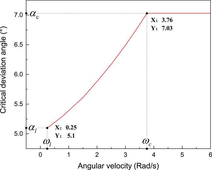
Figure 4. The relationship between critical deviation angle and angular velocity.
As shown in Figure 4, when the system angular velocity is less than the critical angular velocity
In summary, when the system angular velocity is less than the critical angular velocity, the system angular velocity has an impact on the critical deviation angle. As the angular velocity decreases, the critical deviation angle gradually decreases until it approaches extreme deviation angle
From Figure 4, it can also be found that the value of critical angular velocity
From the above analysis, it can be concluded that the critical deviation angle can be used to evaluate the sensitivity of the mechanical stable platform to well deviation. The smaller the value of the critical deviation angle, the more sensitive the mechanical stable platform. Therefore, it can be used as a performance evaluation index for the mechanical stable platform. In order to explore which design parameters have a significant impact on the critical deviation angle, sensitivity analysis is needed to provide ideas for subsequent optimization of parameters. Taking the φ114 mm mechanical stable platform as an example, the parameter range was determined through research on materials and processing technology, as shown in Table 1.
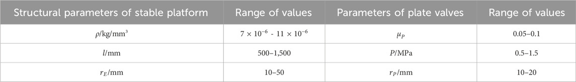
Table 1. Parameters of the mechanical stable platform.
Figure 5 demonstrates the sensitivity analysis results of the critical deviation angle model when the system at normal working speed (
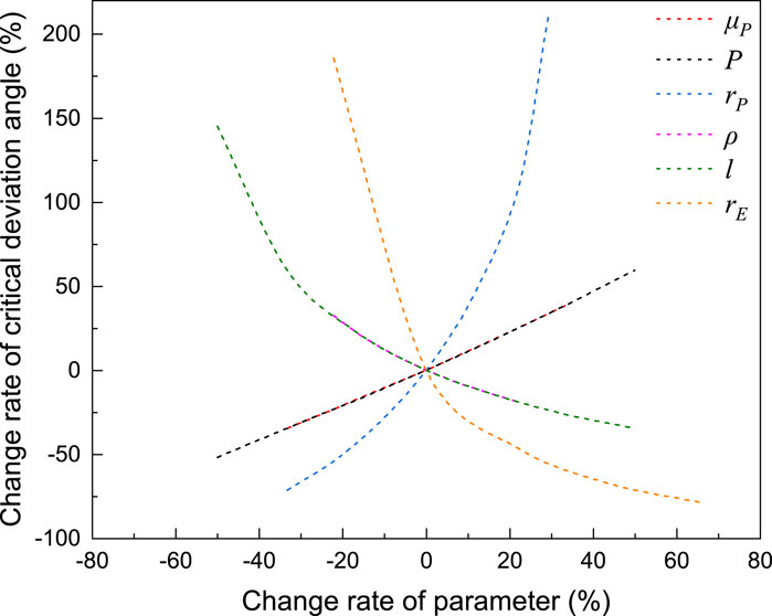
Figure 5. Sensitivity analysis of critical deviation angle model.
Although the above theoretical method has obtained the analytical solutions for the critical deflection angle and the critical deviation angle, there are two shortcomings. One is that the above model only takes into account the initial and termination moments of the eccentric block, so they do not reflect the intermediate motion process, thus ignoring the time dimension. The other is that they do not analyze the motion law of the eccentric block in the right semicircular interval (180°–360°). Therefore, a universal dynamic equation of the eccentric block will be developed in the following.
Firstly, the circular coordinate system shown in Figure 3 can be divided into six regions as (a, b), (b, c), (c, d), (d, e), (e, f), and (f, a) according to the characteristics of the eccentric moment and the friction torque of the plate valves as shown in Figure 6. Define the perpendicular to the plane inward as the positive direction of the torque, according to the right-hand rule. Then establish dynamic equations for each region separately, as shown in Eq. 22.
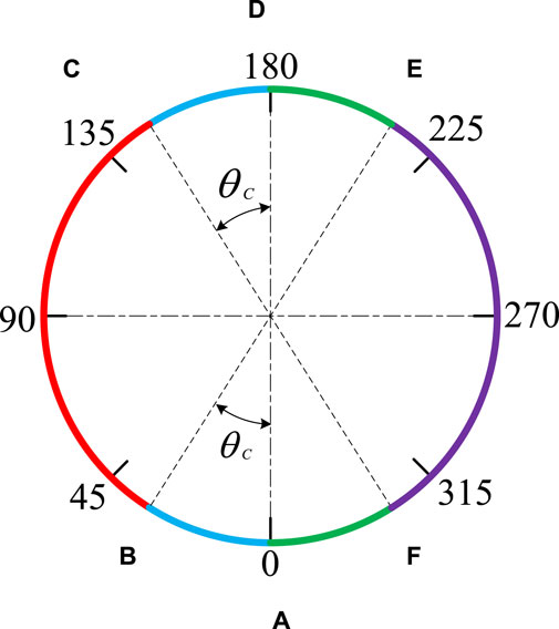
Figure 6. Regional division for eccentric block.
Wherein,
After substituting each parameter into Eq. 22, it was found that the equation is a second-order nonlinear nonhomogeneous ordinary differential equation with piecewise characteristics, which makes the dynamic equation exhibit strong nonlinearity and time-varying characteristics. The above analysis shows that the deflection angle of the eccentric block is large, so it is impossible to linearize the dynamic equations. In summary, it is difficult to obtain an analytical solution for the dynamic equation established by Newtonian vector mechanics.
Although Eq. 22 is difficult to be solved analytically, and thus it is difficult to get the trajectory of the eccentric block in real space, the trajectory of the eccentric block in the phase space can be clearly demonstrated after order reduction. From the above analysis, it can be concluded that when the system is at normal speed and the deviation angle is greater than the critical deviation angle of the mechanical stable platform, the friction torque of the plate valves is always the dynamic friction torque and the eccentric block always moves in the (a, c) region. Eq. 22 can be simplified to Eq. 23.
After substituting each parameter into Eq. 23 and dividing the upper and lower equations, Eq. 24 can be obtained.
Wherein,
After solving the differential equation for Equation 24, Equation (27) can be obtained.
Wherein,
According to Eq. 28, when the angular velocity of the eccentric block is 0,
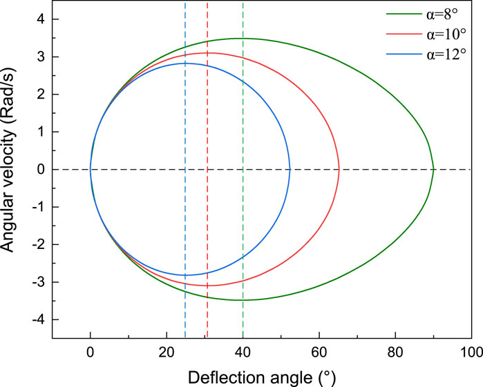
Figure 7. Phase-Graph of eccentric block.
The horizontal axis in Figure 7 represents the deflection angle of the eccentric block, the vertical axis represents the angular velocity, and the three vertical dashed lines represent the critical deflection angles of the eccentric block under three deviation conditions. As shown in the figure, the phase-graph of the eccentric block is a closed approximate elliptical curve, indicating that the motion state of the eccentric block is periodic oscillation. If there is no damping force, the oscillation of the eccentric block will never stop. The abscissa of the right intersection point between the ellipse and the black center dashed line is the extreme deflection angle of the eccentric block. As the deviation decreases, the extreme deflection angle of the eccentric block gradually increases. When the deviation angle is greater than the critical deviation angle, the eccentric block will pass the upper critical deflection angle position and rotation. As the deviation decreases, the oscillation center gradually deviates from the critical deflection angle position.
Although the dynamic equation of the eccentric block under the ideal environment have been established above, when the external environment is non-ideal (such as vibration), the complex nonlinear dynamic characteristics make it difficult to establish the dynamic equation of the system, and the theoretical methods no longer applicable. Therefore, it is particularly important to study the system by numerical simulation.
In response to the difficulties encountered in using vector mechanics, the theory of using mathematical analysis to solve mechanical problems developed rapidly in the 18th century, thus forming the theoretical system of analytical mechanics. It uses energy and work to describe the relationship between object motion and interaction, and establishes a universal form of system dynamics equations through the Darrell principle and virtual displacement principle, with the most representative being the La-grange equation and Hamilton equation. Due to the fact that the Lagrange equation can numerically solve complex multi-body dynamic problems, we adopt this method to establish the dynamic equation of a mechanical stable platform, as shown in Eq. 29 (Lurie, 2013; Liu and Gao, 2017).
Wherein,
In order to ensure good sealing, the upper and lower plate valves will be tightly fitted, causing contact behavior between them. Due to the stability and clear physical meaning of the impact function method, we use the impact function model to calculate the contact force between the plate valves, as shown in Eq. 30.
Wherein,
Due to the rotation of the lower plate valve with the bit and relative rotation with the upper plate valve, the contact between the upper and lower plate valves also causes friction between them. We select the Coulomb Friction Model, which is widely used in the engineering field, to describe the changes in the friction coefficient between the upper and lower plate valves. As the relative speed between the plate valves changes, the friction coefficient between the plate valves transforms between the dynamic and static friction coefficients. To avoid sudden changes in the dynamic and static friction coefficients causing nonconvergence of computer simulation results, a continuous transformation process is set for the dynamic and static friction coefficients with relative speed, as shown in Figure 8. The relationship formula is shown in Eq. 31 (Trinkle et al., 1997).
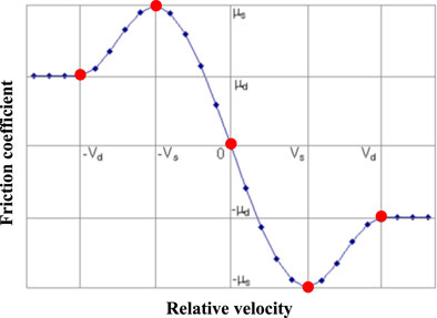
Figure 8. Coulomb friction model.
Wherein,
According to the above theoretical analysis, when the deviation is greater than the critical deviation angle, the eccentric block swings around the center position. When the damping effect is ignored, the oscillation will never stop. However, due to the influence of external environment damping and internal system damping, the mechanical stable platform is a dissipative system. The amplitude of the eccentric block will gradually decay under the damping effect until it finally stabilizes at the critical deflection angle position. We adopt the most commonly used linear viscous damping model in engineering, and equates the damping torque of the system to a viscous damping torque related to the angular velocity of the eccentric block, as shown in Eq. 32 (Adhikari and Woodhouse, 2001).
Wherein,
In order to verify the accuracy of the dynamic simulation model, this paper compares the theoretical calculation results with the simulation calculation results for verification. The parameters for verification are the critical deviation angle and critical deflection angle. The required theoretical model parameters and simulation model parameters are shown in Table 2.
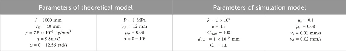
Table 2. Parameters for verify.
Substitute the theoretical model parameters into Eq. 16 to obtain the critical angular velocity of the system
(1) Case
Substituting the theoretical model parameters into Equation 11 and Equation (5), the critical deviation angle
The lower bound and upper bound of the critical deviation angle are set to 7.02° and 7.04°. The simulation model parameters in Table 2 are used to simulate the dynamic response of the eccentric block under the lower and upper bound deviation states. The results are shown in Figure 9.
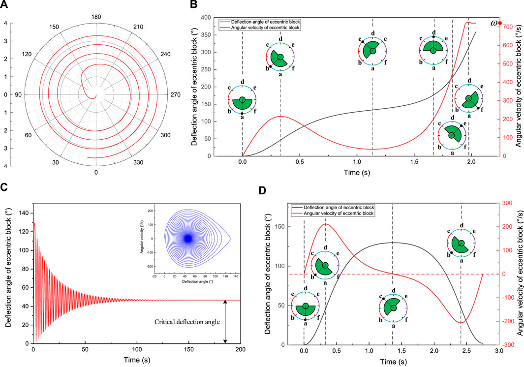
Figure 9. The response of eccentric block at the lower and upper bound of critical deviation angle (
Figure 9A shows the dynamic response of the eccentric block under the lower bound deviation state, which simulates the situation shown in Figure 3D. Due to the rotation of the eccentric block, its deflection angle continuously accumulates, so polar coordinates are used for representation. Establish a polar coordinate system with the lower side of the borehole as the polar origin and the clockwise direction as the positive direction. The polar angle represents the deflection angle of the eccentric block, and the polar diameter represents time. As shown in Figure 9A, when the deviation angle is less than the critical deviation angle, the eccentric block will rotate, causing the mechanical stable platform to lose its ability to sense the deviation.
Figure 9B shows the variation of deflection angle and angular velocity of the eccentric block during the first lap. As shown in the figure, the eccentric block has undergone a process of acceleration, deceleration, and reacceleration. The critical deflection angle position (point b) is the boundary point between acceleration and deceleration. When the eccentric block reach the upper critical deflection angle position (point c), its angular velocity decreases to the minimum (close to 0). Then it accelerate again until the angular velocity exceeds the system angular velocity (720°/s) and reaches its maximum at point f. When the eccentric block enters the (f, a) region, it deceleration again to the system angular velocity and maintain a constant speed until reach point a. The eccentric block then enters the state of periodic unidirectional rotation.
Figure 9C shows the dynamic response of the eccentric block under the upper bound deviation state, which simulates the situation shown in Figure 3F. Create a Cartesian coordinate system with time as the horizontal axis and deflection angle as the vertical axis. From the time-domain and phase diagrams of the eccentric block in Figure 9C, it can be seen that when the deviation angle is greater than the critical deviation angle, the eccentric block does not pass the upper critical deviation angle position, but exhibits oscillation attenuation characteristics. After several swings, it can gradually stop at the critical deviation angle position (
Figure 9D shows the variation of deflection angle and angular velocity of the eccentric block during the first oscillation period. As shown in the figure, the eccentric block has undergone a process of acceleration, deceleration, reverse acceleration, and further deceleration. The critical deflection angle position (point b) is the boundary point between acceleration and deceleration. When the eccentric block approaches the upper critical deflection angle position (point c), its angular velocity decreases to 0, then accelerates in reverse and decelerates again until the angular velocity reaches 0 (due to the damping force, the eccentric block will not reach point a). The eccentric block then enters the state of oscillation attenuation.
(2) Case
Substituting the theoretical model parameters and
Figure 10. The response of eccentric block at the lower and upper bound of critical deviation angle (
As shown in Figure 10A, when the deviation angle is less than the critical deviation angle, the eccentric block will rotate, causing the mechanical stable platform to lose its ability to sense the deviation.
Figure 10B shows the variation of deflection angle and angular velocity of the eccentric block during the first lap. As shown in the figure, the motion state of the eccentric block is roughly similar to the situation shown in Figure 9B. The main difference is that, because the system speed is less than the critical speed, the eccentric block accelerates to the system angular velocity (180°/s) in the (a, b) region and then maintains a constant speed to point b. The eccentric block accelerates again to the system angular velocity in the (c, d) region and maintains a constant speed to point e.
From the time-domain and phase diagrams of the eccentric block in Figure 10C, it can be seen that when the deviation angle is greater than the critical deviation angle, the eccentric block does not pass the upper critical deviation angle position, but exhibits oscillation attenuation characteristics. After several swings, it can gradually stop at the critical deviation angle position (
Figure 10D shows the variation of deflection angle and angular velocity of the eccentric block during the first oscillation period. As shown in the figure, the motion state of the eccentric block is roughly similar to the situation shown in Figure 9D. The main difference is that, because the system speed is less than the critical speed, the eccentric block accelerates to the system angular velocity in the (a, b) region and then maintains a constant speed to point b.
In summary, no matter the system speed is greater or less than the critical speed, the eccentric block is unidirectionally rotating at the lower bound of the critical deviation angle, oscillation attenuation at the upper bound of the critical deviation angle and gradually stabilizes at the critical deflection angle position. Since the difference between the lower and upper bounds is very small (0.02°), there must be a critical state between the lower and upper bounds as shown in Figure 3E. The above analysis enables the theoretical model and simulation model to be verified with each other, and also proves that the simulation model has a high computational accuracy and the parameter values are taken correctly.
When the bit breaks rock underground, it is subjected to strong impact loads, resulting in strong torsional, axial, and lateral vibrations of the drill string. Due to the installation of a stabilizer on the upper part of the vertical drilling system (limited radial displacement) and its large diameter (high bending stiffness), its lateral vibration magnitude is relatively smaller than the other two types of vibration. Therefore, this paper mainly analyzes the influence of torsional vibration, axial vibration, and torsional-axial coupled vibration on the deviation sensitivity of the mechanical stable platform.
In drilling operations, torsional vibration is widely present in the drill string system, so it is not enough to only consider the ideal state of the MVDS moving at a constant speed. The main reason for torsional vibration is the periodic accumulation and release of elastic potential energy inside the drill string when the bit breaks rock, and its motion form is the periodic rotation through acceleration-deceleration-acceleration. The torsional vibration model can be characterized by the trigonometric function of angular velocity, which is expressed as Eq. 33 (Li, 2018).
Wherein,
According to the amplitude of torsional vibration, it is divided into mild, moderate, and severe. The level of torsional vibration is evaluated by Eq. 34.
Set system angular velocity ω to 720°/s (120 r/min), the values of amplitude
Figure 11 shows the influence of torsional vibration on the critical deviation angle of a mechanical stable platform. The X-axis and Y-axis represent the amplitude and frequency of torsional vibration, respectively, and the Z-axis represents the critical deviation angle. From the figure, it can be seen that the critical deviation angle is jointly affected by the amplitude and frequency of torsional vibration, and its variation range is between the extreme deviation angle
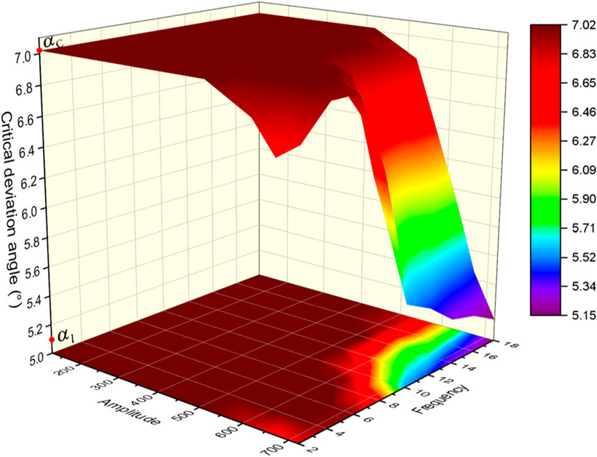
Figure 11. The influence of torsional vibration on the critical deviation angle.
To explain the above phenomenon, this paper takes the three typical torsional vibration situations included in the above figure as examples, extracts the simulation results at their upper bounds, and conducts detailed analysis.
(1) Case
This torsional vibration situation can represent the dark red area in the mapping region, and torsional vibration will not affect the critical deviation angle. In this case, due to the small amplitude of torsional vibration, the system angular velocity is always greater than the angular velocity of the eccentric block, resulting in no difference in the motion state of the eccentric block compared to the situation shown in Figures 9C,D.
(2) Case
This torsional vibration situation can represent the color gradient area in the mapping region, and torsional vibration have a more intense impact on the critical deviation angle. As shown in Figure 12A, when the amplitude and frequency of torsional vibration increase to a certain extent, the critical deviation angle of the mechanical stable platform can be reduced, thereby increasing its critical deflection angle. Figure 12B shows the time-domain diagrams of the deflection angle, angular velocity of the eccentric block, and angular velocity of torsional vibration in the first oscillation period. As shown in the figure, during the rising stage of the black solid line (representing the deflection angle of the eccentric block), there are four intersections between the red solid line (representing the angular velocity of the eccentric block) and the blue dashed line (representing the angular velocity of torsional vibration), indicating the existence of two time periods during which the angular velocity of torsional vibration is smaller than the angular velocity of the eccentric block, resulting in the negative direction of the plate valves friction torque and the negative work on the eccentric block. Due to the presence of two negative works, the eccentric block exhibits a deceleration behavior in the (a, b) region, and intensifies the deceleration process in the (b, c) region, allowing its angular velocity decelerate to the zero in the (b, c) region. Therefore, a certain degree of torsional vibration can effectively reduce the critical deviation angle of the mechanical stable platform. In addition, it can be further inferred from Figure 12B that as the amplitude and frequency of torsional vibration increase, the horizontal distance between the intersection points gradually increases, resulting in a further increase in the magnitude of negative work done by the friction torque, thereby further weakening the kinetic energy of the eccentric block in the (a, c) region. Therefore, the critical deviation angle can gradually decrease until it approaches the extreme deviation angle
(3) Case
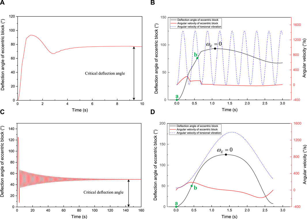
Figure 12. The response of eccentric block under the second and third torsional vibration situation: (A) Cartesian plot (second situation); (B) Cartesian plot (second situation and first oscillation period); (C) Cartesian plot (third situation); (D) Cartesian plot (third situation and first oscillation period).
This torsional vibration situation can represent the light red area in the mapping region, and torsional vibration have a slight impact on the critical deviation angle. As shown in Figure 12C, when the amplitude of torsional vibration increases to a certain extent and the frequency decreases to a certain extent, the critical deviation angle of the mechanical stable platform can also be slightly reduced, thereby increasing its critical deflection angle. Figure 12D shows the time-domain diagrams of the deflection angle, angular velocity of the eccentric block, and angular velocity of torsional vibration in the first oscillation period. As shown in the figure, due to the large amplitude and small frequency of torsional vibration, its initial angular velocity is low and its growth rate is slow, which enables the angular velocity of the eccentric block to catch up with the torsional vibration angular velocity in the (a, b) region. when the angular velocity of the eccentric block reaches the system angular velocity in the (a, b) region, it will rotate at the same speed as the system. Figure 12D shows the above situation, where the red solid line and blue dashed line overlap in the (a, b) region until the torsional vibration angular acceleration is greater than the maximum angular acceleration that the eccentric block can obtain, indicating that the slow increase in angular velocity during the initial torsional vibration suppresses the increase in kinetic energy of the eccentric block in the acceleration zone. This enables its angular velocity decelerate to the zero in the (b, c) region, thereby reducing the critical deviation angle.
To sum up, although torsional vibration can cause many negative impacts on drilling operations, a certain degree of torsional vibration can appropriately reduce the critical deviation angle of the mechanical stable platform, thereby effectively improving its deviation sensitivity.
Axial vibration is more likely to occur during drilling in vertical wells because the wellbore damping effect in vertical wells is lower than that in inclined wells, and energy is more easily transferred along the drill string. It is caused by the alternating contact between the bit teeth and the protruding rock at the bottom of the well, as well as the elastic deformation of the drill string, and its motion form is the periodic reciprocating motion through upward-downward-upward. The axial vibration model can be characterized by the trigonometric function of linear displacement, which is expressed as Eq. 35 (Li and Guo, 2007).
Wherein,
After taking the derivative of Equation 35 twice, the maximum acceleration generated by axial vibration can be obtained, as shown in Equation 36.
According to the maximum acceleration generated by axial vibration, it is divided into mild, moderate, and severe. The level of axial vibration is evaluated by Eq. 37.
The values of amplitude
Figure 13 shows the influence of axial vibration on the critical deviation angle of a mechanical stable platform. The X-axis and Y-axis represent the amplitude and frequency of axial vibration, respectively, and the Z-axis represents the critical deviation angle. From the figure, it can be seen that the critical deviation angle is jointly affected by the amplitude and frequency of axial vibration, and its value is always greater than
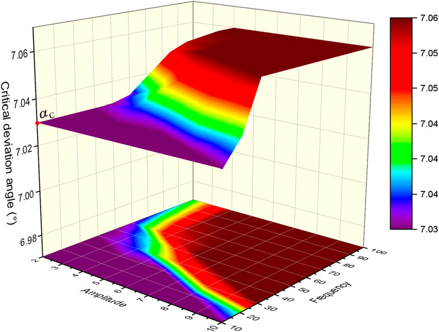
Figure 13. The influence of axial vibration on the critical deviation angle.
The influence of axial vibration on the critical deviation angle is mainly caused by the longitudinal acceleration. During the axial vibration process, the longitudinal acceleration of the upper plate valve on the stable platform is in a fluctuating state, causing the contact force between the upper and lower plate valves to be in a fluctuating state, thereby causing the friction torque between the upper and lower plate valves to also be in a fluctuating state. Figure 14 shows the linear acceleration and contact force of the plate valves generated by axial vibrations with different amplitudes and frequencies. As shown in the figure, axial vibration causes both the acceleration and the contact force of the plate valves to fluctuate in a sinusoidal manner. With the increase of frequency or amplitude, the extreme values of vibration acceleration and the contact force also increase, and the axial vibration becomes stronger. Therefore, its impact on the critical deviation angle is greater. The acceleration curves under different axial vibration all fluctuate around the acceleration zero point, and the contact force curves of the plate valves under different axial vibration all fluctuate around 454N (contact force of the plate valves without axial vibration). Although axial vibration can exacerbate the extreme values of acceleration and contact force, the cancellation effect makes its impact on the critical deviation angle tiny.
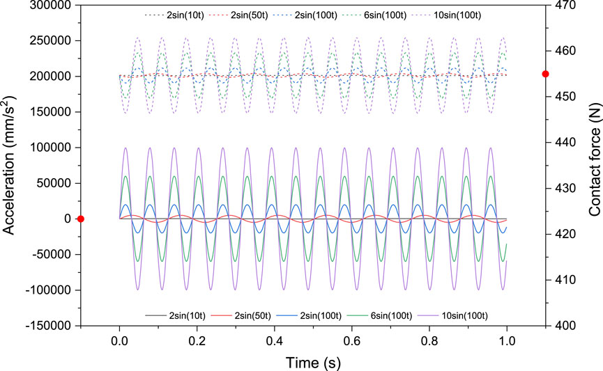
Figure 14. Acceleration and contact force of plate valves under different axial vibrations.
In summary, axial vibration causes a slight increase in the critical deviation angle of mechanical stable platforms over
During the drilling process, the vibration state of the drill string is sometimes not singular, but a coupled state of multiple vibration forms coexisting. In addition to the individual effects of torsional vibration and axial vibration, mechanical stable platform will also be subject to the coupling effects of the two vibration forms. Through the above analysis, it can be seen that the effect of axial vibration on the critical deviation angle can finally be attributed to the effect of the maximum acceleration generated by vibration. The critical deviation angle of the mechanical stable platform under mild axial vibration (
Figure 15 show the influence of torsional vibration on the critical deviation angle under severe, moderate and mild axial vibration respectively. Subfigure A, C, E show the variation law of the critical deviation angle under coupled vibration and subfigure B, D, F show the variation law of the difference between the critical deviation angle under coupled vibration and single torsional vibration. From Figures 15A,C,E, it can be seen that the variation law of critical deviation angle under coupled vibration is similar to that under single torsional vibration, indicating that torsional vibration plays a dominant role, and the additional effect of axial vibration is relatively small. As shown in Figures 15B,D,F, the additional effect of axial vibration in coupled vibration mainly acts on the large amplitude region of torsional vibration. The effect of axial vibration causes the critical deviation angle to fluctuate up and down on the basis of a single torsional vibration value, but the fluctuation amplitude is relatively small, with a maximum of only 0.2°. As the intensity of axial vibration gradually decreases and the surface shape gradually flattens, it indicates that the difference in critical deviation angle gradually decreases, and the additional effect of axial vibration in coupled vibration gradually weakens.
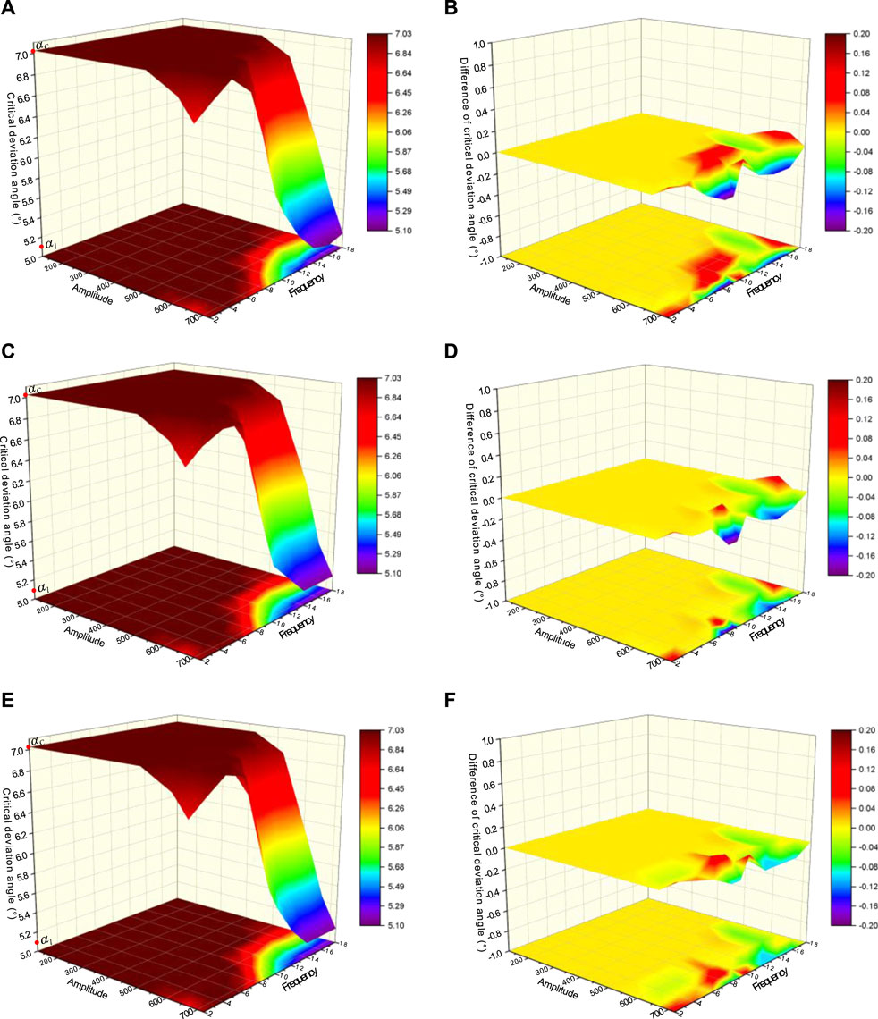
Figure 15. The influence of torsional vibration on critical deviation angle under severe, moderate, and mild axial vibration: (A) Absolute value (severe axial vibration); (B) Relative value (severe axial vibration); (C) Absolute value (moderate axial vibration); (D) Relative value (moderate axial vibration); (E) Absolute value (mild axial vibration); (F) Relative value (mild axial vibration).
In summary, torsional vibration plays a dominant role in coupled vibration. The additional effect of axial vibration is relatively small and gradually weakens as its intensity decreases.
In this paper, theoretical mechanics is introduced to establish the critical deviation angle model for the mechanical stable platform. Multi-body dynamics simulation is applied to mutually verify the models and further analyze the effect of vibration. The main conclusions are as follows.
1. The critical deviation angle can be used to evaluate the sensitivity of the mechanical stable platform to well deviation. When the deviation angle is greater than the critical deviation angle, the eccentric block can gradually stop at the lower critical deflection angle position under the damping effect, and the MVDS will begin to correct the deviation.
2. When the system angular velocity is less than the critical angular velocity, the system angular velocity has an impact on the critical deviation angle. As the angular velocity decreases, the critical deviation angle gradually decreases until it approaches extreme deviation angle
3. In order to improve the performance of the system, the values of
4. The critical deviation angle is jointly affected by the amplitude and frequency of torsional vibration, and its variation range is between the extreme deviation angle
The raw data supporting the conclusions of this article will be made available by the authors, without undue reservation.
LC: Writing–review and editing, Writing–original draft, Software, Methodology. QS: Writing–review and editing, Project administration, Funding acquisition. BL: Writing–review and editing, Supervision, TF: Writing–review and editing.
The author(s) declare that financial support was received for the research, authorship, and/or publication of this article. This work was supported by the National Key Research and Development Program of China (Grant No. 2023YFF0615403), Scientific Research and Technology Development Project of CNPC (Grant No. 2021DJ4601), and Scientific Research and Technology Development Project of CNPC (Grant No. 2019D-5010–18).
The authors would like to thank the editor and the reviewers for their helpful comments.
Authors LC and QS were employed by China National Petroleum Corporation.
The remaining authors declare that the research was conducted in the absence of any commercial or financial relationships that could be construed as a potential conflict of interest.
All claims expressed in this article are solely those of the authors and do not necessarily represent those of their affiliated organizations, or those of the publisher, the editors and the reviewers. Any product that may be evaluated in this article, or claim that may be made by its manufacturer, is not guaranteed or endorsed by the publisher.
Adhikari, S., and Woodhouse, J. (2001). Identification of damping: part 1, viscous damping. J. Sound Vib. 243, 43–61. doi:10.1006/jsvi.2000.3391
Bram, K., Draxler, J., Hirschmann, G., Zoth, G., Hiron, S., and Kühr, M. (1988). The KTB borehole—Germany’s superdeep telescope into the earth’s crust. Oilfield Rev. 7, 4–22.
Chai, L., Zhang, K., Yang, D., Liu, B., and Zhang, D. (2021). Integral modeling for deviation correction trajectory of the mechanical vertical drilling system. Machines 9, 161. doi:10.3390/machines9080161
Chur, C., and Oppelt, J. (1993). “Vertical drilling technology: a milestone in directional drilling,” in SPE/IADC drilling Conference and exhibition. SPE.
Claus, C., Thomas, B., Bernhard, E., Axel, S., Trach, T., and Lothar, W. (1995). “KTB-4 years experience at the limits of drilling technology,” in SPE/IADC drilling Conference and exhibition. SPE.
Comeaux, B., Gibb, J., Kirkhope, K., and Shaw, P. (2007). “New automatic vertical drilling system for high temperature, harsh environment and performance drilling applications,” in Offshore mediterranean Conference and exhibition: omc. OMC-2007-2052.
Dongxia, J., Jing, Z., and Xinsheng, F. (2000). Stability controlling model of built-in eccentric directional controller. J. Xi’an Shiyou Univ. Sci. Ed. (01), 44–49+0. doi:10.3969/j.issn.1673-064X.2000.01.013
Jones, S., Feddema, C., Castro, J., and Sugiura, J. (2016). “Fully mechanical vertical drilling system delivers RSS performance in vertical drilling applications while providing an economical alternative to conventional rotary steerable systems set-up for vertical hold mode,” in SPE/IADC drilling Conference and exhibition: spe. D011S003R006.
Laiju, H., Hongjian, N., Jinhai, Z., Zhihe, L., and Zhonghua, W. (2008). Development of mechanical tool for automatic vertical drilling. Acta Pet. Sin. 29, 766. doi:10.3321/j.issn:0253-2697.2008.05.025
Li, L. (2018). Research on dynamics and optimization method of mechanical stable platform in automatic vertical drilling tools. Beijing, China: China University of Geosciences.
Li, L., Xue, Q., Liu, B., Wang, J., and Li, X. (2018). The dynamics of eccentric block in a fully mechanical vertical drilling tool under the effect of torsional vibration. Adv. Mech. Eng. 10, 168781401877049. doi:10.1177/1687814018770497
Li, L., Xue, Q., Liu, B., Zhao, L., and Li, X. (2017). “Design and mechanical analysis of a new automatic vertical drilling tool used in a slim borehole,” in IOP conference series: earth and environmental science (London, UK: IOP Publishing).012017.
Li, Z., and Guo, B. (2007). “Analysis of longitudinal vibration of drillstring in air and gas drilling,” in SPE rocky mountain Petroleum technology conference/low-permeability reservoirs symposium: spe. SPE-107697-MS.
Lin, C., Zhang, K., and Baolin, L. (2020a). Classification and development status of automatic vertical drilling tools. China Pet. Mach. 48, 1–11. doi:10.16082/j.cnki.issn.1001-4578.2020.01.001
Lin, C., Zhang, K., and Yaopeng, Z. (2020b). Performance test of the pushing actuator of the small diameter vertical drilling tool. Explor. Eng. (Rock Soil Drill. Tunneling) 47, 87–93. doi:10.12143/j.tkgc.2020.04.013
Liu, Y., and Gao, D. (2017). A nonlinear dynamic model for characterizing downhole motions of drill-string in a deviated well. J. Nat. Gas Sci. Eng. 38, 466–474. doi:10.1016/j.jngse.2017.01.006
Ma, C., Zhang, K., Liu, B., Wang, Y., Yan, C., and Chai, L. (2023). Optimization research for the adjusting device of the mechanical vertical drilling tool based on the adjusting torque. Machines 11, 509. doi:10.3390/machines11050509
Ma, T., Chen, P., and Zhao, J. (2016). Overview on vertical and directional drilling technologies for the exploration and exploitation of deep petroleum resources. Geomechanics Geophys. Geo-Energy Geo-Resources 2, 365–395. doi:10.1007/s40948-016-0038-y
Oppelt, J., Chur, C., Feld, D., and Juergens, R. (1991). “New concepts for vertical drilling of boreholes,” in SPE/IADC drilling Conference and exhibition. SPE.
Ranran, L., Kai, Z., Lin, C., Long, Z., and Baolin, L. (2022). Simulation research on influencing factors of stabilization platform for mechanical vertical drilling tools. Pet. Drill. Tech. 50, 51–60. doi:10.11911/syztjs.2021106
Reich, M., Oesterberg, M., Montes, H., and Treviranus, J. (2003). “Straight down to success: performance review of a vertical drilling system,” in SPE annual technical Conference and exhibition: spe.
Trinkle, J. C., Pang, J. S., Sudarsky, S., and Lo, G. (1997). On dynamic multi-rigid-body contact problems with Coulomb friction. ZAMM-Journal Appl. Math. Mechanics/Zeitschrift für Angewandte Math. und Mech. 77, 267–279. doi:10.1002/zamm.19970770411
Wang, J., Hu, Y., Liu, Z., Li, L., Liu, B., and Huang, L. (2021). Dynamic characteristics and key parameter optimization of mechanical automatic vertical drilling tools. Shock Vib. 2021, 1–17. doi:10.1155/2021/8813984
Wang, J., Xue, Q., Liu, B., Li, F., and Zhang, Z. (2020a). Numerical study on the characteristics and effects of gap flow in two parallel rotating disks. Math. Problems Eng. 2020, 1–14. doi:10.1155/2020/4514936
Keywords: mechanical stable platform, critical deviation angle, well deviation sensitivity, eccentric block, effect of vibration
Citation: Chai L, Sun Q, Liu B and Tang F (2024) Working characteristic research on the mechanical stable platform of the automatic vertical drilling system. Front. Energy Res. 12:1426840. doi: 10.3389/fenrg.2024.1426840
Received: 02 May 2024; Accepted: 17 June 2024;
Published: 11 July 2024.
Edited by:
Tianshou Ma, Southwest Petroleum University, ChinaReviewed by:
Peng Wang, China University of Petroleum, ChinaCopyright © 2024 Chai, Sun, Liu and Tang. This is an open-access article distributed under the terms of the Creative Commons Attribution License (CC BY). The use, distribution or reproduction in other forums is permitted, provided the original author(s) and the copyright owner(s) are credited and that the original publication in this journal is cited, in accordance with accepted academic practice. No use, distribution or reproduction is permitted which does not comply with these terms.
*Correspondence: Lin Chai, bGluY2hhaUBwZXRyb2NoaW5hLmNvbS5jbg==
Disclaimer: All claims expressed in this article are solely those of the authors and do not necessarily represent those of their affiliated organizations, or those of the publisher, the editors and the reviewers. Any product that may be evaluated in this article or claim that may be made by its manufacturer is not guaranteed or endorsed by the publisher.
Research integrity at Frontiers
Learn more about the work of our research integrity team to safeguard the quality of each article we publish.