 Wang Zhidong
 Han Xiaonan
- State Grid Economic and Technological Research Institute Co., LTD, China
Introduction: Super capacitors were regarded as one of the most effective frequency regulation technologies in power systems. The major issue of applying super capacitors for frequency regulation is the limited energy capacity and the high construction costs. The pumped storage units have been developed and applied in power systems for decades, whereas it was rarely operated to regulate the system frequency due to the operation limitations. The pumped storage units could be operated as a hydro generator under the generation mode and provide effective frequency regulation service with the conventional automatic generation control (AGC) system while its output power was constant under the pumping mode.
Method: In this paper, the pumped storage unit was controlled to participate in frequency regulation under the generation mode with super capacitors. Considering the AGC system could not consider the state of charging (SOC) of super capacitors for frequency regulation, an optimization model was proposed to determine the operation points for super capacitors and pumped storage units under a model predictive control (MPC) strategy to regulate the system frequency for power systems.
Results and Discussion: Based on the various operation scenarios, the effectiveness and costs of pumped storage units and super capacitors to provide frequency regulation services were discussed. It was indicated that pumped storage units and super capacitors were effective technologies for power systems.
1 Introduction
Nowadays, with the large-scale integration of renewable energy sources into power systems, the required capacity for frequency regulation has increased, which is caused by the fluctuations and uncertainties of these renewable sources (Wu et al., 2015a; Zhao et al., 2019a; Liu et al., 2020). The traditional coal-fired generators under the traditional AGC frequency regulation systems only provide limited frequency regulation capacity due to the limited ramping capabilities. Super capacitors, with their fast response speed and bi-directional operation capability, were regarded as an effective technology for frequency regulation. However, super capacitors have some disadvantages, such as limited energy capacities, capacity degradations, and high construction costs (Geng et al., 2015; Li, 2021). Pumped storage units have been developed for decades in power systems. The large power and energy capacity of the pumped storage units were valuable for the operation of power systems. In most cases, the pumped storage units participated in the peak shaving applications and operated as the system reserve.
Some economical evaluation approaches of pumped storage units have been proposed and studied. Zhang and Cai (2014) proposed an indices system that includes the coal consumption index, coal conservation ratio index, the value of peak loads, and probabilities of energy shortage. An entropy weight formula was proposed to optimally dispatch the pumped storage units by determining the weight vector. Wang et al. (2010) analyzed the economic benefits of pumped storage units with different auxiliary services. A fuzzy evaluation approach was proposed for pumped storage units with different kinds of auxiliary services. Wen et al. (2015) studied the environmental benefits of pumped storage units to minimize the total costs of power systems with environment costs. An optimization model for the daily operation of pumped storage units was proposed with the practical operation data from the Mengxi power system and the Hohhot pumped storage units. An optimization model for coordinating the operations of pumped storage units and wind power was proposed by Xu et al. (2013). The carbon emission cost was considered to determine the optimal operation schedule of pumped storage units during peak periods. The whole life-cycle cost of pumped storage units was considered in the study by Xu et al. (2023) and Li et al. (2018), and the benefits of carbon emission reduction and operation costs were studied. The demand response units that coordinated with pumped storage to reduce the operation costs were studied by Chen et al. (2022). A day-ahead market optimization model was proposed for the power system with pumped storage units by Wang et al. (2023). Wu et al. (2008), Papaefthymiou et al. (2010), and Papakonstantinou et al. (2023) studied various operation methods for pumped storage units in isolated power systems. The variable-speed pumped storage units were analyzed in some studies (Lung et al., 2007; Zhu et al., 2021; Chen et al., 2023), and the technical characteristics indicate that they can enhance the integrating capability of renewable energy. The round operation efficiency of electricity to electricity is approximately 75% to 80% for pumped storage units (Liang et al., 2015). It reduces the economic payback of pumped storage units when they participate in peak shaving applications. If the electricity price difference between the peak time and valley time is too small, the pumped storage unit may not get any payback from shaving the energy from peak periods to valley periods considering the energy lost (Chen et al.).
The pumped storage units can be operated in different modes, such as the pumped mode, generation mode, and standstill mode. The pumped storage units can be operated as a hydro generator to regulate the system frequency under the generation mode. In this way, the pumped storage unit can provide frequency regulation service under the generator mode. The output power of a pumped storage unit is a constant value and cannot be adjusted under the pumped mode. The power ramps during the switching of operation modes of pumped storage units within minutes could be regarded as a kind of valuable flexible operation resource for power systems, especially for the ramping up and ramping down periods, and have potential for frequency regulation applications (Wang and Han, 2024). If the pumped storage units could provide frequency regulation service for power systems, the pumped storage units could obtain additional economic paybacks from power systems.
Numerous studies explored the strategies for BESS to facilitate regulating the frequency for power systems. Wu et al. (2015b) proposed a strategy to allocate the output of energy storage for frequency regulation. Sometimes, energy storage systems may not fully respond to the regulation commands due to the limited energy capacity. A distributed algorithm was proposed to minimize the total life operation cost of the super capacitors by Zhao et al. (2019b). Moreover, a control strategy for energy storage SOC recovery output was proposed by considering both the SOC status and frequency fluctuations by Yan et al. (2022). In addition, based on the fuzzy control theory, a control strategy for the energy storage system was established in the study by Liu et al. (2017), aiming to mitigate fluctuations in photovoltaic power stations and avoid excessive charging and discharging of energy storage systems, thereby reducing the damage to the energy storage systems. It indicates that the coordination of super capacitors with pumped storage units can enhance the frequency regulation capabilities for the hybrid system. However, an effective coordination method was required for the hybrid system.
The model predictive control (MPC) method has been widely used in industry applications. As indicated by Yan et al. (2022), the MPC method could effectively operate the pumped storage units for frequency regulation by considering various operation constraints. It indicates that the MPC method has the potential to coordinate the operation of the hybrid systems with pumped storage units and super capacitors. In this paper, an MPC control strategy was proposed for the hybrid system, and the effectiveness of pumped storage units for frequency regulation was studied and discussed.
2 The mathematic models of pumped storage units and super capacitors
2.1 The operation models
The physical constraints of pumped storage units and super capacitors were identified in this paper for the operation models. The power ramps generated during the switching of operation modes of pumped storage units were represented in the proposed mathematic models.
There are two types of pumped storage units in power systems: the conventional pumped storage units and the variable-speed pumped storage units. Both of them include three operational modes: the pumped mode, generation mode, and standstill mode. The operation modes can be switched within minutes, and large power ramps will be generated during the switching of modes. Compared to the conventional pumped storage units, the variable-speed pumped storage units have a larger adjustable operation range in both the generation and pump modes. Most of the pumped storage units in the power systems are conventional pumped storage units. The operation model of both the conventional pumped storage units and variable-speed pumped storage units were proposed in this paper as follows:
Here,
Compared to conventional pumped storage units, variable-speed pumped storage units were equipped with power converters to adjust the speed of turbines of the pumped storage units. Similar to that of the generation mode, the output can be adjusted within a specified range under the pumped model for pumped storage units. Equation 2 can be revised for a variable-speed pumped storage unit, the description is shown in Equation 9.
Different from the pumped storage units, super capacitors can be operated continuously within the full range of the output power in both charging and discharging operation modes. In this way, the super capacitors can be coordinated with pumped storage units to regulate frequency effectively. The operation characteristics and constraints were described as follows:
Here,
2.2 The costs models
The construction cost per energy and power capacity of pumped storage units were the lowest in all the energy storage technologies for power systems. In this way, the pumped storage units participated in peak shaving to obtain the paybacks in electricity markets by price arbitrage in most cases. The pumped storage units could also support the voltage under the generation mode by generating reactive power. Moreover, the pumped storage units can be paid to provide reserve service when the price difference is not large enough for peak shaving applications. The available reserve capacities of pumped storage were different in different operation modes.
The costs and benefits calculation model for pumped storage units with an electricity market environment can be described as follows:
Equation 13 and Equation 14 indicate that whether the pumped storage units could obtain benefits from the electricity markets depends on the difference of electricity prices.
The benefits obtained from frequency regulation service contain two parts, the description in detail is shown in Equation 15 the part calculated by the power capacity for frequency regulation and the part calculated by the total exchanged energy for frequency regulation service.
3 The MPC strategy for frequency regulation
The model predictive control (MPC) method is an advanced control strategy that determines the optimal control actions for the system by considering the system outputs in the future control intervals with the dynamic system model. In this way, an optimization model was required to determine these optimal operation actions with the dynamic system model for the system. MPC was widely applied in industrial process control, energy management, smart transportation systems, and other fields. In this paper, the MPC method was employed to determine the output power and operation models for the power system with pumped storage units, coal-fired generators, and super capacitors to regulate the system frequency effectively. Due to the energy capacity limitations of super capacitors, if the super capacitor or the pumped storage unit reaches the upper or lower limit of the energy capacity during regulating the system frequency, the output power of the operating unit will be reduced to zero within seconds, and a large frequency deviation will be cased as a consequence. In this way, the MPC method can coordinate different operation resources to regulate the system frequency effectively by avoiding the energy constraints of energy storage devices to be reached.
As shown in Figure 1, the relationship between the power deviation (
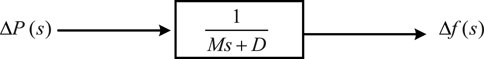
Figure 1. Relationship between power deviation and frequency deviation.
The transfer function as shown in Equation 16 can be expanded by first-order Taylor series approximation as follows:
Finally, the frequency deviations can be calculated in the discrete formation as in Equation 17. In this paper, the control diagram of three kinds of operation resources: pumped storage units, super capacitors, and conventional thermal generator, is shown in Figure 2.
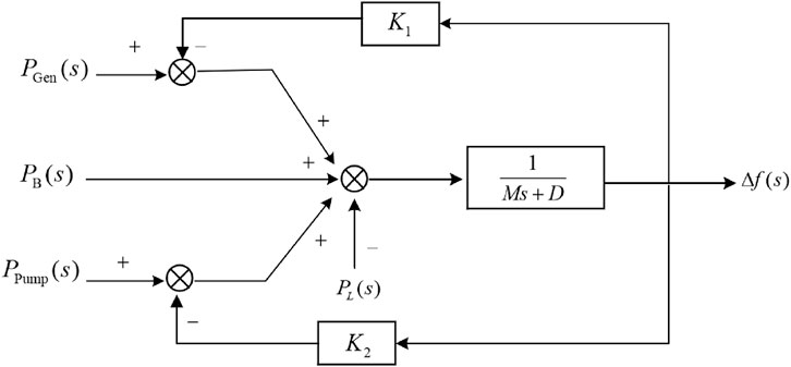
Figure 2. Control graph.
The objective function and constrains of the proposed MPC controller were represented as follows:
Here,
The proposed MPC strategy considers N control intervals for the proposed optimization model. The optimal actions of the system, represented by
4 Case studies
In order to verify the effectiveness of the proposed MPC strategy and evaluate the capability of pumped storage units in frequency regulation, the MPC controller was studied with different operation scenarios. As indicated in the proposed mathematic models for the MPC controller, three kinds of operation resources: coal-fired generators, super capacitors, and pumped storage units, were included in the proposed MPC controller. The MPC control flowchart is shown in Figure 3. The parameters in the proposed MPC controller of the case studies are shown in Table 1. Parameters in this table are from one real project.
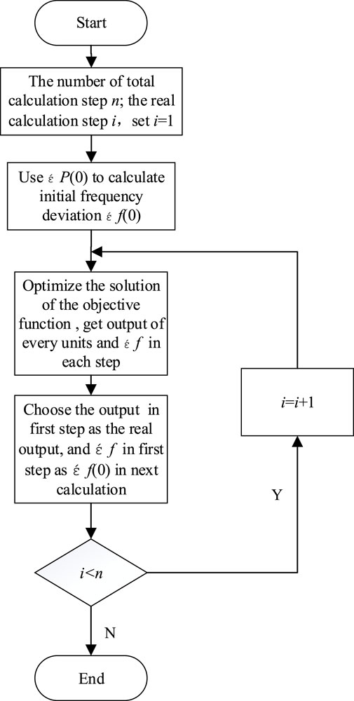
Figure 3. MPC control flowchart.

Table 1. Parameters of the proposed mathematic model for the case studies.
4.1 Case 1
In this case, the system load was stepped to 30 MW from 0 MW at 10s, as shown in Figure 4A. In this scenario, there is no pumped storage unit for the frequency regulation. The frequency deviations, output power of coal-fired thermal generator, output power of super capacitors, and SOC of super capacitors are shown in Figures 4B–E.
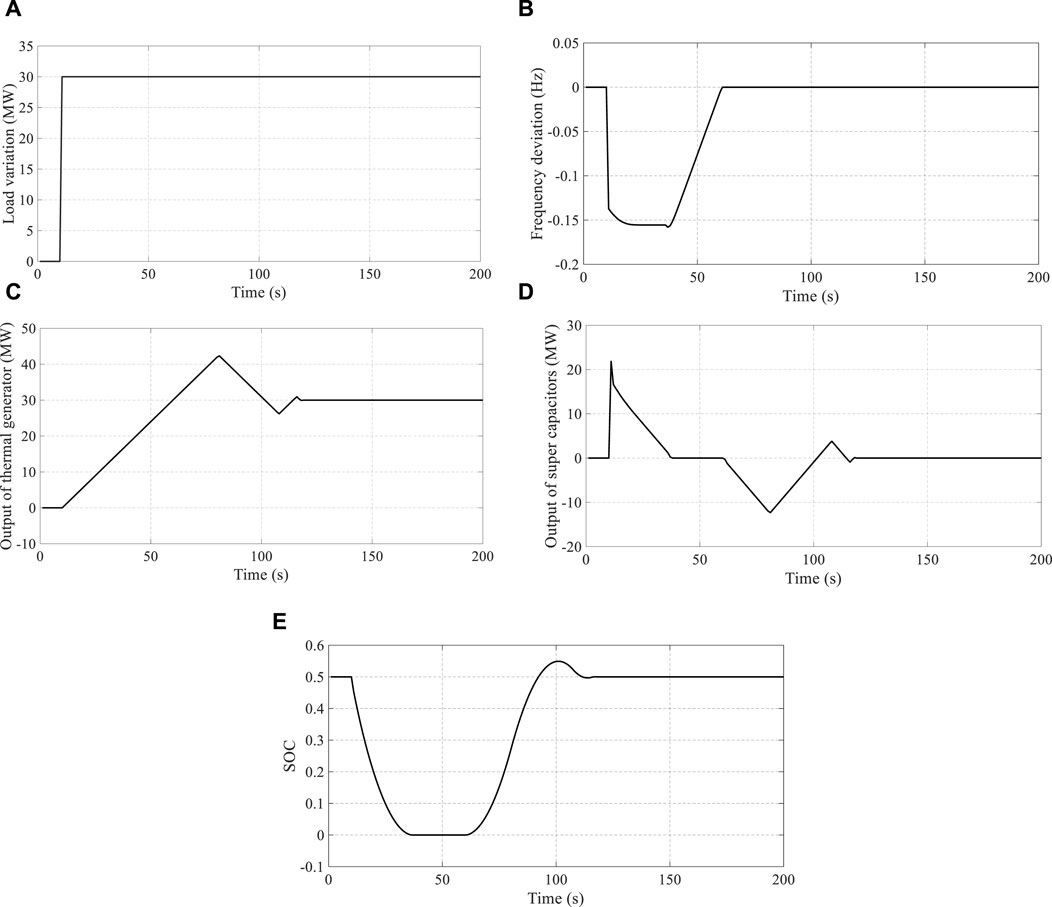
Figure 4. Simulation results under the condition without pumped storage unit: (A) variation of load, (B) frequency deviation, (C) output power of thermal generator, (D) output power of super capacitors, and (E) SOC of super capacitors.
Due to the limited ramping capability of coal-fired thermal generators, the active power balance of the system could not be maintained during the whole ramping period and large frequency deviations were caused in the same periods, as indicated in Figure 4B. During a step disturbance of the loads, as shown in Figure 4A, the output power of the super capacitors reached its maximum output power and the thermal generator ramps up with maximum ramping capability. To ensure the super capacitors could provide frequency regulation service in the coming control intervals, the state of charge (SOC) of the super capacitors should be controlled to the value of 0.5. As a result, after the frequency deviations caused by the load step variations were regulated within a small range, the output power of the thermal generator was still increased to charge the super capacitors by the thermal generator. Eventually, the output power of thermal generator equals to 30 MW, and the SOC of the super capacitors was set to the optimal value of 0.5. In this case, the total power deviations were compensated by the thermal generator, and the output power of the super capacitors was reduced to zero according to the proposed MPC controller.
Based on the initial operation results as indicated in Figure 4, the pumped storage unit with a rated power of 30 MW was added to the power system and participated in frequency regulation. The adjustable output power of the pumped storage unit was between 18 MW and 30 MW under the generation mode. The results of frequency deviations, the output power of thermal generator, the output power of super capacitors, the SOC of super capacitors, and the output power of pumped storage unit are shown in Figure 5.
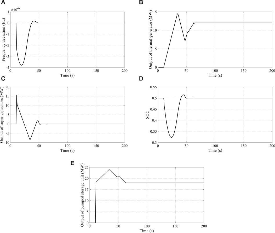
Figure 5. Simulation results under the condition with pumped storage unit: (A) frequency deviation, (B) output power of thermal generator, (C) output power of super capacitors, (D) SOC of super capacitors, and (E) output power of pumped storage unit.
After the pumped storage unit participated in the frequency regulation, the output power of the pumped storage units can be adjusted between 18 MW and 30 MW, which indicates that the pumped storage unit can increase the frequency regulation capacity with the adjustable output power of 12 MW. The frequency deviations caused by the step variations of the system load can be reduced effectively, as shown in Figure 5A. The variations of the SOC for the super capacitors were smaller than the previous results. It indicates that the step variations of the system loads were mainly compensated by the pumped storage unit and the super capacitors since 10 s in the power system. Similar to the previous results, the output power of the super capacitors will reduce to zero after the step variations of the system loads are compensated, and the SOC of the super capacitors will be controlled to 0.5 finally. Considering the minimum output power of the pumped storage unit was set to 18 MW under the generation mode, the output power of the thermal generator equals to 12 MW at the end of the control intervals. In this way, the step variations of the system loads were compensated by both the thermal generator and the pumped storage unit. After the pumped storage unit was shut down, the thermal generator fully compensated the load variations. In this case, the pumped storage unit was also limited by the constraint of ramping rate under the generation mode. It indicates that the pumped storage unit could not respond to the load variation by itself. With the facilitation of the super capacitors, the step variation of the system loads can be compensated effectively. However, super capacitor was limited by the energy capacity.
Compared to the pumped storage unit, the output power of the thermal generator was constrained by the ramping rate since the step variations of the system loads. The thermal generator could not compensate the loads effectively at the beginning. As a consequence, the super capacitors and the pumped storage unit play an important role in frequency regulation. In order to study the performance of pumped storage units in frequency regulation, a scenario with larger capacities of super capacitors and thermal generators but no pumped storage units was studied. When the frequency deviations in this scenario were similar to those in the scenario with the pumped storage unit, the equivalent capacity of thermal generators and super capacitors for the pumped storage unit could be obtained. The control results of a scenario with a 1,800-MW thermal generator and an 80-MW super capacitor and a scenario with a 12,600-MW thermal generator and a 25-MW super capacitor were studied, and are shown in Figure 6.
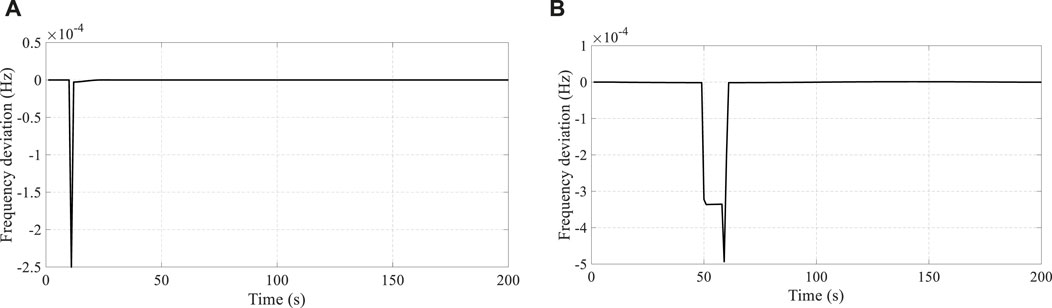
Figure 6. (A) Frequency deviations under 1,800 MW thermal generator and 80 MW super capacitors. (B) Frequency deviations under 12,600 MW thermal generators and 25 MW super capacitors.
As indicated in Figure 6, the frequency deviations under the scenario with a 1,800-MW thermal generator and an 80-MW super capacitor and the scenario with a 12,600-MW thermal generator and a 50-MW super capacitor were similar with the results as in Figure 5A. In this way, the 30-MW pumped storage unit can be replaced by a 55-MW super capacitor or a 10,800-MW thermal generator. Different combinations of the thermal generator and super capacitors may cause different operation performances.
4.2 Case 2
In the second case, the control performance for the super capacitors, pumped storage unit, and the thermal generator under a scenario with ramping variations of system loads were studied. The system loads were increased at the rate of 5 MW/s since 10 s and reached to 50 MW at the end. Similar to case #1, the control results without pumped storage units were studied first. The scenario of load variations, results of frequency deviations, the output power of thermal generator, the output power of super capacitors, and the SOC of super capacitors are shown in Figure 7.
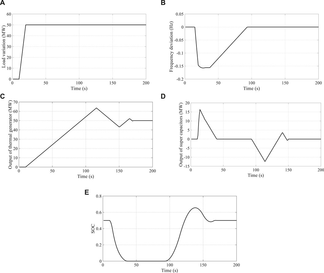
Figure 7. Simulation results under the condition without pumped storage unit. (A) The variation of load. (B) Frequency deviation. (C) Output power of thermal generator. (D) Output power of super capacitors. (E) The SOC of super capacitors.
In this case, the variation rates of the system loads were smaller than those in case #1. In this way, a better control performance can be achieved with the same operation resources. As shown in Figures 7A, B, similar frequency deviations can be obtained with larger variations of 50 MW in this case. Considering that the variations of loads are larger than those in case #1, the SOC of the super capacitor touches the lower limit, as shown in Figure 7E. In the same periods when low limitation was reached, the largest frequency deviations occurred. The SOC of the super capacitor was controlled back to 0.5, as shown in Figure 7E. As shown in Figures 7C, D, the output power of the thermal generator is larger, and the super capacitor’s output power is smaller than that in case #1.
Then the pumped storage unit participated in frequency regulation, and the frequency deviations, the output power of thermal generator, the output power of super capacitors, the SOC of super capacitors, and the output power of pumped storage unit were shown as follows:
The frequency deviations were smaller in this scenario with the pumped storage unit participating in frequency regulation, as shown in Figure 8A. The variations of the SOC for the super capacitors were smaller, as shown in Figure 8D. In the early stage of the load increase, the pumped storage unit was not operated in the generation mode to regulate the system frequency, as indicated in Figure 8E. The minimum output power of the pumped storage units under the generation mode was set to 18 MW, which is larger than the size of load variations in the early stage. In this way, if the pumped storage unit was controlled to participate in frequency regulation since 10 s, the power ramps during the switching of operation modes for pumped storage would cause large frequency deviations. When the summation of the output power for the pumped storage unit and thermal generator exceeds 50 MW, the super capacitors was charged to control the SOC back to the target value of 0.5, as shown in Figures 8C–E.
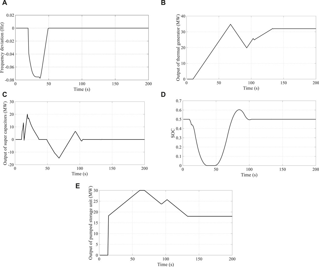
Figure 8. Results under the condition with pumped storage unit: (A) frequency deviations, (B) output power of thermal generator, (C) output power of super capacitors, (D) SOC of super capacitors, and (E) output power of pumped storage unit.
Considering the existence of the pumped storage unit, the ramping capability of the power system can be enhanced when the pumped storage unit is operated under the generation mode. Moreover, the ramping capability can also be enhanced by switching the operation mode of the pumped storage unit from the standstill mode to the generation mode due to the power ramps generated during the switching. Similar with case #1, the pumped storage unit was replaced by the 4,320 MW thermal generator or 150 MW super capacitor as a new scenario. The operation results are shown as in Figure 9.
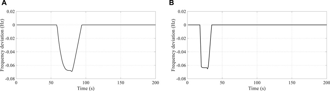
Figure 9. (A) Frequency deviation under 1,800 MW thermal generator and 175 MW super capacitors. (B) Frequency deviation under 6,120 MW thermal generator and 25 MW super capacitors;
As indicated in Figure 9A to Figure 9B, the frequency deviations under the three scenarios were similar, and all of them could be regulated effectively. In this way, the equivalent capacity for the pumped storage unit can be calculated based on the results of the case studies. The 30-MW pumped storage unit can be replaced by a 4,320 MW conventional thermal generator or a 150-MW super capacitors.
4.3 Case 3
The equivalent capacity between pumped storage units and traditional thermal power generators for frequency regulation under different scenarios with ramping rates of load variations was studied in this case. The ramping limits of traditional thermal power generators were set to 0.6 MW/s, which equals to 2% of the rated power per minute. The super capacitors were also considered for frequency regulation in this case. Compared with case #1 and case #2, the ramping rates of the system loads were set from 3 MW/s to 7 MW/s with a 10-s duration in this case.
Under different ramping rates of system loads
Figure 10 and Table 2 show that the equivalent capacity ratio kept increasing when the ramping rate was lower than 5 MW/s and decreased when the ramping rate of system loads was larger than 5 MW/s. It was due to the limited output power capacity of pumped storage units. When the ramping rates of the system loads were larger, larger regulation capacities were required.
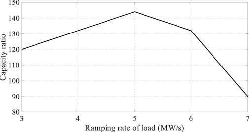
Figure 10. Equivalent capacity ratio of pumped storage unit and thermal generators.

Table 2. Equivalent capacity ratio of pumped storage units to thermal generators under different ramping rates of system loads.
Based on the above results, the super capacitors were then removed, and the equivalent capacity ratios were studied, and are shown in Table 3 and Figure 11.

Table 3. Equivalent capacity ratio of pumped storage unit to thermal generators 408 under different ramping rates of system loads without super capacitors.

Figure 11. Equivalent capacity ratio of pumped storage unit to thermal generators.
Without the existence of super capacitors in this scenario, the fast response capability of the frequency regulation will be reduced. As a consequence, the equivalent capacity ratio of the pumped storage unit to thermal generators will be larger than that in the previous scenario, as shown in Figure 11. It indicates that the super capacitors played an important role in frequency regulation with thermal generators and pumped storage units.
4.4 Economic evaluation of pumped storage units
Based on the results of the equivalent capacity ratio of the pumped storage unit to thermal generators in the previous case studies under different scenarios, the economic evaluation results of pumped storage units were discussed in this section. The benefits of pumped storage units obtained from the energy electricity market and frequency regulation auxiliary market were studied, and the typical electricity price curve and frequency regulation price curve are shown in Figure 12.
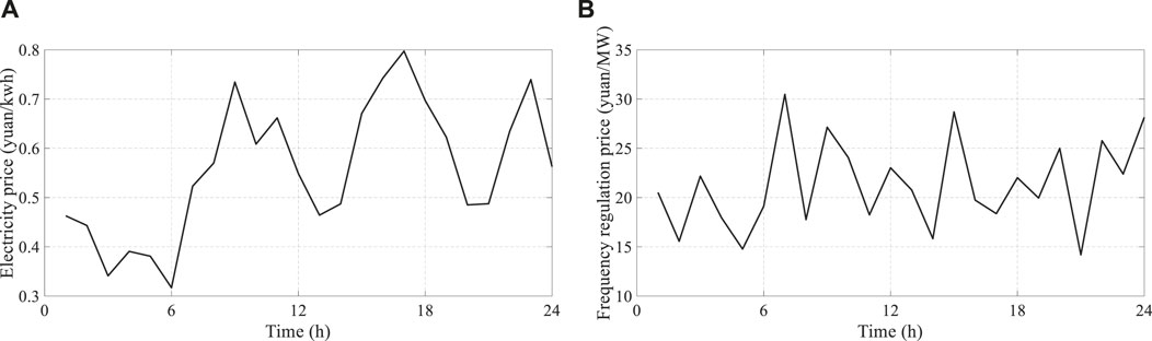
Figure 12. (A) Electricity price and (B) price of frequency regulation capacity.
The capacity of thermal generators that qualified for frequency regulation was set to 5% in this paper. The benefits of pumped storage units and thermal generators can be obtained from the markets by participating in peak shaving and frequency regulation, which can be calculated as in Table 4. The performance factor in Equation 15 can be normalized as Equation 27.
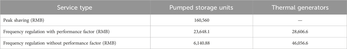
Table 4. Economic benefits for pumped storage units from energy and frequency regulation market.
When the performance factor was not considered, the benefits obtained from frequency regulation were larger for the thermal generators than those when the performance factor was considered. The pumped storage units can achieve more benefits when considering the performance factor. The reason was that the equivalent capacity ratios of pumped storage unit to thermal generators in frequency regulation were larger than 20, which was calculated by the 5% capacity ratio of thermal generators. The mechanism of performance factor can increase the benefits for pumped storage units in frequency regulation applications.
5 Conclusion
In this paper, a MPC controller was proposed to control the super capacitors, thermal generators, and pumped storage units to participate in frequency regulation in different scenarios. When the system load is ramped up or down, the pumped storage unit can enhance the ramping capability by switching its operation modes. In this way, the pumped storage unit can replace the thermal generator with larger rated capacity to maintain a similar frequency regulation capability. Moreover, the operation costs and benefits of the pumped storage unit were also evaluated in this paper, and the pumped storage unit can obtain benefits from various kinds of technology services. Based on the implementation of electricity markets in China, the pump storage unit can obtain more benefits by providing various technology services.
Data availability statement
The original contributions presented in the study are included in the article/supplementary material; further inquiries can be directed to the corresponding author.
Author contributions
WZ: methodology, project administration, supervision, and writing–original draft. HX: software, visualization, and writing–review and editing. YW: investigation, software, and Writing–review and editing.
Funding
The author(s) declare that financial support was received for the research, authorship, and/or publication of this article. This research was funded by the Science and Technology Project of State Power Economic Research Institute Co., Ltd. The grant number is 524408220001. The funder was not involved in the study design, collection, analysis, interpretation of data, the writing of this article, or the decision to submit it for publication.
Conflict of interest
Authors WZ, HX, and YW were employed by State Grid Economic and Technological Research Institute Co., LTD.
Publisher’s note
All claims expressed in this article are solely those of the authors and do not necessarily represent those of their affiliated organizations, or those of the publisher, the editors, and the reviewers. Any product that may be evaluated in this article, or claim that may be made by its manufacturer, is not guaranteed or endorsed by the publisher.
References
Chen, L., Li, Z., and Liu, Y. Technical characteristics and research framework of large AC excitation variable speed. Power Syst. Technol. 1-10. 2024-04-05]. doi:10.13335/j.1000-3673.pst.2023.1434
Chen, W., Zhang, Z., Zhang, G., Chen, L., and Zhang, F. (2022). Robust unit commitment of power systems integrated wind power considering demand response and pumped storage units. Electr. Power Eng. Technol. 41 (2), 75–82.
Chen, Y., Xu, W., Liu, Y., Bao, Z., Mao, Z., and Rashad, E. M. (2023). Modeling and transient response analysis of doubly-fed variable speed pumped storage unit in pumping mode. IEEE Trans. Industrial Electron. 70 (10), 9935–9947. doi:10.1109/tie.2022.3224154
Geng, Y., Yang, Z., and Lin, F. (2015) “Basic analysis of wireless power transfer systems using super-capacitor as load,” in Iecon 2015 - 41st annual conference of the IEEE industrial electronics society. Yokohama, Japan, 09-12 November 2015 (IEEE), doi:10.1109/IECON.2015.7392410
Li, D., Li, X., Huang, W., Chen, S., and Ma, G. (2018). Assessment on whole life cycle of pumped storage system based on LCA. Water Power 44 (06), 90–93.
Li, F. (2021) “Design of energy saving vehicle based on super capacitor,” in 2021 IEEE 5th advanced information technology, electronic and automation control conference (IAEAC). Chongqing, China, 12–14 March 2021 (IEEE), 1735–1739. doi:10.1109/IAEAC50856.2021.9391048
Liang, L., Hou, Y., and Hill, D. J. (2017). Design guidelines for MPC-based frequency regulation for islanded microgrids with storage voltage and ramping constraints. IET Gener. Transmiss.Distrib. 11 (8), 1200–1210. doi:10.1049/iet-rpg.2016.0242
Liang, L., Li, P., Liu, J., and Zhan, C. (2015). Study on the control strategy of pumped storage power station for frequency regulation. High. Volt. Eng. 41 (10), 3288–3295. doi:10.13336/J.1003-6520.hVE.2015.10.014
Liu, B., Yin, M. L., Lin, Q. R., Lin, L., Yuan, S., Ma, J., et al. (2017). “Control strategy of BESS for smoothing fluctuation of photovoltaic power based on fuzzy control theory,” inProceedings of 2017 Chinese automation congress (CAC), 2744–2749.
Liu, G., Lu, Z., Yang, Z., Liu, X., and Zhao, X. Distributed energy storage aggregation control method considering SOC equalization. Power capacitors and reactive power compensation, 2020, 41 (03). doi:10.14044/j.1674-1757.pcrpc.2020.03.028
Lung, J., Lu, Y., Hung, W., and Kao, W. S. (2007). Modeling and dynamic simulations of doubly fed adjustable-speed pumped storage units. IEEE Trans. Energy Convers. 22 (2), 250–258. doi:10.1109/tec.2006.875481
Papaefthymiou, S., Karamanou, E., Pathanassiou, S., and Papadopoulos, M. P. (2010). A wind-hydro-pumped storage station leading to high RES penetration in the autonomous island system of Ikaria. IEEE Trans. Sustain. Energy 1 (3), 163–172. doi:10.1109/tste.2010.2059053
Papakonstantinou, A., Konstanteas, A., and Papathanassiou, S. (2023). Solutions to enhance frequency regulation in an island system with pumped-hydro storage under 100% renewable energy penetration. IEEE Access 11, 76675–76690. doi:10.1109/access.2023.3296890
Wang, J., Zhang, L., Zhao, Z., and Li, Y. (2023). Marketization operation mechanism and clearing model of day-ahead market for pumped storage stations. Automation Electr. Power Syst. 47 (12), 145–153.
Wang, W., Wang, G., Zhou, X., and Dong, B. (2010). Evaluation index system and method of pumped-storage power plants serving power grids. Power Syst. Clean Energy 26 (08), 88–92.
Wang, Y., and Han, X. (2024). The evaluation method for pumped storage plants with diversified economic values. Shandong Electr. power 51 (02), 25–36. doi:10.20097/j.cnki.issn1007-9904.2024.02.003
Wen, Q., Li, R., Wu, Y., Jin, X., Lou, S., and Zhou, B. (2015). Daily operation optimization of pumped storage power station considering environmental benefits. South. Power Syst. Technol. 9 (5), 71–75. doi:10.13648/j.cnki.issn1674-0629.2015.05.12
Wu, C., Lee, W., Cheng, C., and Lan, H. W. (2008). Role and value of pumped storage units in an ancillary services market for isolated power systems—simulation in the Taiwan power system. IEEE Trans. Industry Appl. 44 (6), 1924–1929. doi:10.1109/tia.2008.2006313
Wu, M., Cui, G., Ji, Y., Liu, H., Li, Y., Yu, H., et al. (2015a). Consistent and active control for distributed energy storage system in distribution network. Electr. Power Constr. 36 (06), 20–26.
Wu, M., Cui, G., Ji, Y., Liu, H., and Li, Y. (2015b). Consistent and active control for distributed energy storage system in distribution network. Electr. Power Constr. 36 (06), 20–26.
Xu, F., Chen, L., Jin, H., and Liu, Z. (2013). Modeling and application analysis of optimal joint operation of pumped storage power station and wind power. Automation Electr. Power Syst. 37 (01), 149–154.
Xu, Y., Liu, H., Pan, F., Zhu, J., Liang, Z., and Jing, T. (2023). Research on carbon emission reduction for pumped storage based on emission factor method. Electr. Power Demand Side Manag. 25 (04), 48–54.
Yan, G., Wang, M., Duan, S., Zhang, W., and Li, J. (2022). Primary frequency regulation control strategy of energy storage considering state of charge recovery. Automation Electr. Power Syst. 46 (21), 52–61.
Zhang, Z., and Cai, X. (2014). Determination of pumped storage capacity based on entropy. Electr. Mach. Control 18 (3), 34–39. doi:10.15938/j.MC2014.03.004
Zhao, W., Xiang, X., Zheng, Y., Yi, B., and Meng, J. (2019b). Network operation platform architecture and control strategy of distributed energy storage systems. High. Volt. Eng. 45 (10), 3256–3262. doi:10.13336/J.1003-6520.hVE.20181121006
Zhao, W., Xiao, Xi., Zheng, Y., Yi, B., Meng, J., and Luo, M. (2019a). Network operation platform architecture and control strategy of distributed energy storage systems. High. Volt. Eng. 45 (10). doi:10.13336/j.1003-6520.hve.20181121006
Keywords: frequency regulation, model predictive control, pumped storage units, super capacitors, alternative coefficient
Citation: Zhidong W, Xiaonan H and Ying W (2024) The design of a model predictive control strategy and performance analysis for pumped storage units and super capacitors in power systems. Front. Energy Res. 12:1425169. doi: 10.3389/fenrg.2024.1425169
Received: 29 April 2024; Accepted: 31 July 2024;
Published: 22 October 2024.
Edited by:
Zhi-Wei Liu, Huazhong University of Science and Technology, ChinaReviewed by:
Rongpeng Liu, McGill University, CanadaWenqian Yin, Nanjing Tech University, China
Lin Zeng, Cornell University, United States
Copyright © 2024 Zhidong, Xiaonan and Ying. This is an open-access article distributed under the terms of the Creative Commons Attribution License (CC BY). The use, distribution or reproduction in other forums is permitted, provided the original author(s) and the copyright owner(s) are credited and that the original publication in this journal is cited, in accordance with accepted academic practice. No use, distribution or reproduction is permitted which does not comply with these terms.
*Correspondence: Wang Ying, d2FuZ3lpbmc5MDE1QDEyNi5jb20=