 Chao Wu
 Zhanqi Huang
 Yong Wang1
- 1Renewable Energy and Automotive Electronics Laboratory, Department of Electrical Engineering, Shanghai Jiao Tong University, Shanghai, China
- 2AAU Energy, Aalborg University, Aalborg, Denmark
Existing transient stability analysis of grid-following (GFL) converters mainly focuses on the dynamics of the phase-locked loop (PLL), while current loop dynamics are usually neglected due to their faster response than PLL. However, this article reveals that active current may not be able to track its reference quickly during severe grid faults even with high current loop bandwidth, which leads to a non-negligible impact on the transient stability of GFL converters. Furthermore, this article discusses the intrinsic mechanism of why active current cannot track its reference quickly during severe grid faults and establishes a refined third-order transient synchronization model that offers a more accurate assessment of transient stability during severe grid faults than the conventional second-order model.
1 Introduction
With the continuous integration of renewable energy into modern power systems through grid-following (GFL) converters, the transient stability of GFL converters during grid faults is receiving increasing attention. It has been found that a GFL converter may experience loss of synchronization (LOS) during grid faults (Göksu et al., 2014; Xiong et al., 2020). Various analysis techniques have been applied to understand the synchronization instability mechanism, such as the equal-area criteria (He et al., 2021), phase portraits (Wu and Wang, 2020), and the energy function method (Tian et al., 2022).
The aforementioned studies mainly focus on the dynamics of the phase-locked loop (PLL), neglecting the current loop dynamics due to their faster response. However, it has been pointed out that ignoring current loop dynamics when the current loop bandwidth is not high enough may lead to incorrect transient stability assessment (Chen et al., 2020). Then, a high-order transient synchronization model considering the coupling effect between the PLL and current loop is established to analyze the impact mechanism of current loop dynamics (Hu et al., 2021). Furthermore, the work by Wu et al. (2024) gives a conservative bandwidth boundary that can ignore the current loop dynamics. The above studies suggest that the current loop dynamics may harm the transient stability of GFL converters. Nevertheless, the changes in the current reference are not considered, which could potentially invalidate the conclusion during severe grid faults.
In fact, according to the grid code requirements, GFL converters must inject reactive current to support the grid voltage during the low-voltage ride-through process. Particularly, GFL converters should inject pure reactive current during severe grid faults (Yuan et al., 2019). Under this situation, this article observes that although reactive current tracks its reference quickly, active current may undergo obvious dynamic attenuation even with high current loop bandwidth. This phenomenon challenges the assumption of treating the current loop as a unity gain in transient stability modeling, as the active current dynamics have a non-negligible impact on the transient stability. The zero-pole characteristics of the current loop are analyzed to reveal the intrinsic mechanism of why active current cannot track its reference quickly during severe grid faults. Then, a refined third-order transient synchronization model considering active current dynamics is established, which offers a more accurate assessment of the transient stability during severe grid faults than the conventional second-order model. Finally, the impact of active current dynamics is validated through experimental results.
2 Misjudgment of the second-order model
Figure 1A illustrates the topology and control diagram of the GFL converter. Upcc = Upcc∠θpcc represents the voltage of the point of common coupling (PCC). Ug = Ug∠θg represents the grid voltage. Uc represents the voltage at the converter port. Ipcc is the output current of the converter. Lf and Rf are the filter inductance and parasitic resistance. Lg and Rg are the grid inductance and resistance.
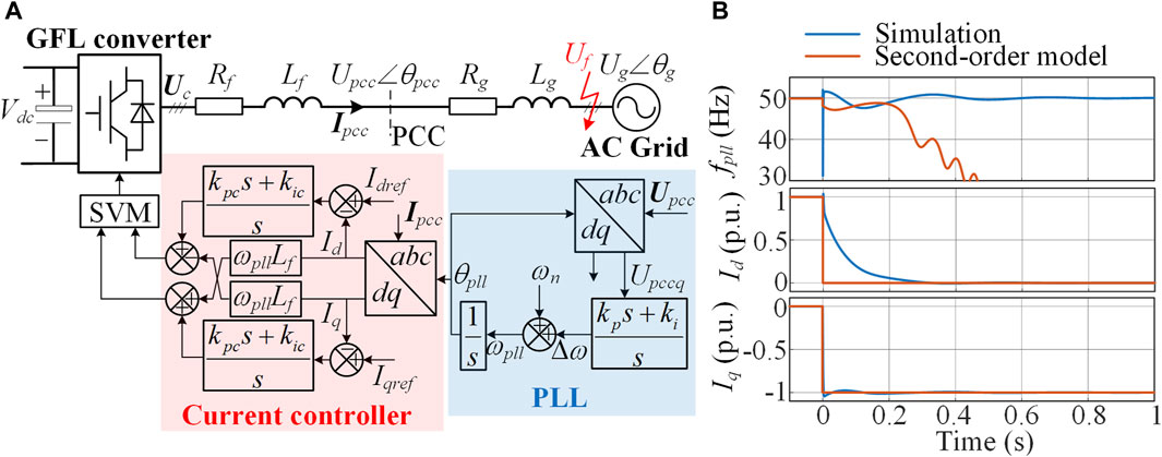
Figure 1. (A) Topology and control diagram of the GFL converter, and (B) simulation results and solutions of the second-order model with a grid fault voltage of Uf = 0.05 p.u.
A synchronous reference frame PLL is used to extract the phase angle information of the point of common coupling (PCC) voltage, in which θpll and ωpll are the output phase angle and angular frequency, respectively. ωn is the norm angular frequency, which is a constant of 100π. kp and ki are the PI parameters of the PLL. The current control in Figure 1A is oriented by the PLL. The outer loop control is disconnected during grid faults, and the current references Idref and Iqref are directly designated according to the grid code (Yuan et al., 2019; He et al., 2021). The PI parameters of the current control are denoted as kpc and kic.
According to Tian et al. (2022), if the current loop is approximated as a unity gain, that is, Id ≈ Idref and Iq ≈ Iqref, the transient synchronization process of the GFL converter during grid faults can be described by a second-order nonlinear model as (1), in which the phase error of the PLL is defined as δ = θpll−θg.
When a severe grid fault occurs with a fault voltage of Uf = 0.05 p.u., simulation results and solutions of the second-order model are as shown in Figure 1B. The solutions of the second-order model show that the PLL frequency fpll is unable to converge, and LOS occurs. However, the simulation results demonstrate that only the reactive current Iq tracks its reference quickly, while active current Id undergoes obvious dynamic attenuation even with a high current loop bandwidth of 500 Hz. The simulation system ultimately maintains synchronicity with the grid, which contradicts the results of the second-order model. The above results indicate that the second-order model cannot capture the dynamic process of active current during severe grid faults, leading to a misjudgment of transient stability.
3 Intrinsic mechanism of active current dynamics during severe grid faults
According to the main circuit structure in Figure 1A, the dq-axis voltage at the converter port can be obtained as (2), where R = Rf + Rg represents the sum of the parasitic filter resistance and the grid resistance and L = Lf + Lg represents the sum of the filter inductance and the grid inductance. s is the Laplace operator.
The output of the current controller is approximately equal to Ucd and Ucq. So, according to the control structure, the control equations for Ucd and Ucq are obtained as follows:
Combining (2) and (3), the dq-axis current can be derived as follows:
According to Eqs 4, 5, the impact of grid voltage changes on the current dynamics is characterized by G2(s). Because G2(s) is a bandpass filter, the bandwidth of the current loop cannot reflect the speed of dynamic response caused by grid voltage changes. Therefore, even if the current loop bandwidth is large enough, it cannot guarantee that the current dynamics caused by grid voltage changes will be fast.
The zero-pole characteristics of the current loop are analyzed to reveal the intrinsic mechanism of why active current cannot track its reference quickly during severe grid faults. According to the zero-pole elimination approach, the parameters of the current loop are set as kpc = ωcLf and kic = ωcRf, where ωc represents the open-loop crossover angular frequency. This configuration results in a non-dominant pole p1 and a dominant pole p2 on the negative real axis. The approximate expressions for the poles are given as Eqs 6, 7
The zero of G1(s) is z1 = −kic/kpc, which is approximately equal to the dominant pole p2 because the P gain of the current controller kpc is typically much larger than the resistance R. Hence, z1 and p2 are canceled out, leading to a fast response to changes in the current reference. However, the zero of G2(s) is located at the origin, which cannot be canceled by the dominant pole. Therefore, the response speed of G2(s) is much lower than that of G1(s).
Based on the above analysis, the current dynamics are dominated by p2 and the zero of G2(s), while G1(s) and the non-dominant pole of G2(s) can be neglected. Consequently, the expressions for the current dynamics ΔIdq can be formulated as (8), where δ0 and Iq0 represent the stable phase error and the reactive current prior to the grid fault, respectively.
From the expression of ΔIq, the input includes three terms: Uf sinδ, −ωpllLgId, and −RgIq0. During severe faults, the fault voltage Uf is small. The converter must output reactive current to support the grid voltage, so the active current Id cannot be very large. In addition, the pre-fault reactive current Iq0 is generally 0. Therefore, the reactive current dynamics are small, that is, ΔIq≈0, which means that the reactive current can track its reference quickly. However, the input of the active current dynamics has two large terms ωpllLgIq and Ugcosδ0, leading to obvious active current dynamics.
4 Third-order transient synchronization model
According to the above analysis, the active current dynamics are much larger than the reactive current dynamics during severe grid faults. Additionally, the input voltage of the PLL includes the grid impedance voltage drop RgIq + XgId. Typically, Xg is greater than Rg, so the active current dynamics have a dominant impact on the transient synchronization process, while the impact of the reactive current dynamics can be ignored.
Considering the active current dynamics, the q-axis component of the PCC voltage is corrected as
According to Equation 8, voltage disturbances generate the active current dynamics through a high-pass filter. The grid voltage sag and switching of the reactive current reference have the main impact on the current dynamics, while the slow changes in the phase error δ and the PLL frequency ωpll have a relatively small impact. Hence, the active current dynamics can be approximated as
According to the PLL structure in Figure 1A, the dynamics of the PLL are expressed as
Combining Equations 9–11 and taking the phase error δ, the angular frequency error Δω, and the active current dynamics ΔId as state variables, a third-order state space equation is derived as
According to the Eq 12, a refined third-order transient synchronization model of the GFL converter is established, as illustrated in Figure 2A. The black part is a PLL-based second-order transient synchronization model, while the red part represents the impact of active current dynamics on PLL dynamics. The transient active current ΔId generates a transient voltage drop ΔUL on the grid impedance, which affects the PCC voltage and subsequently affects the transient synchronization process.
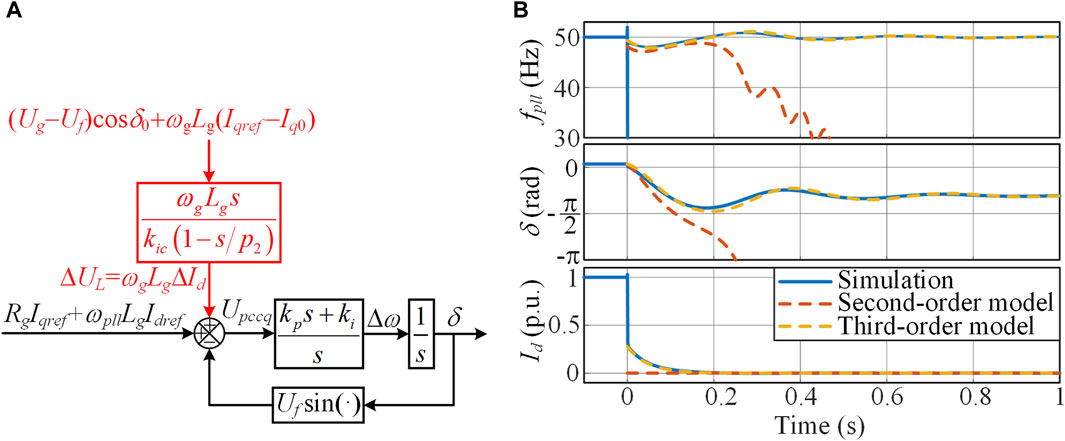
Figure 2. (A) Third-order transient synchronization model, and (B) transient response with a fault voltage of Uf = 0.05 p.u.
5 Simulation and experimental verification
A full-order simulation model based on Figure 1A is constructed using MATLAB/Simulink to validate the correctness of the third-order transient synchronization model, and the simulation results are compared with the solutions of the reduced-order models. The rated voltage and rated power of the system are 690 V and 1.5 MW, respectively. The parameters related to the filter and grid impedance are Lf = 0.1 mH, Rf = 2.1 mΩ, Lg = 0.11 mH, and Rg = 13 mΩ. The damping ratio of the PLL is 1.2, and the bandwidth is approximately 50 Hz. The parameters of the current loop are kpc = 0.95 and kic = 20.
With a fault voltage of Uf = 0.05 p.u., the transient response is shown in Figure 2B. The third-order model closely aligns with the simulation results, while the second-order model does not match the simulation results, validating the correctness of the third-order transient synchronization model.
Experiments are conducted in a control hardware-in-loop (CHIL) platform to verify the impact of active current dynamics. The detailed experimental platform is shown in Figure 3. The main circuit is developed in Typhoon 602+, and the system is controlled by a TMS320F28335/Spartan 6 XC6SLX16 DSP + FPGA control board. The sampling frequency is set as 5 kHz. Other parameters are consistent with the simulation parameters above.
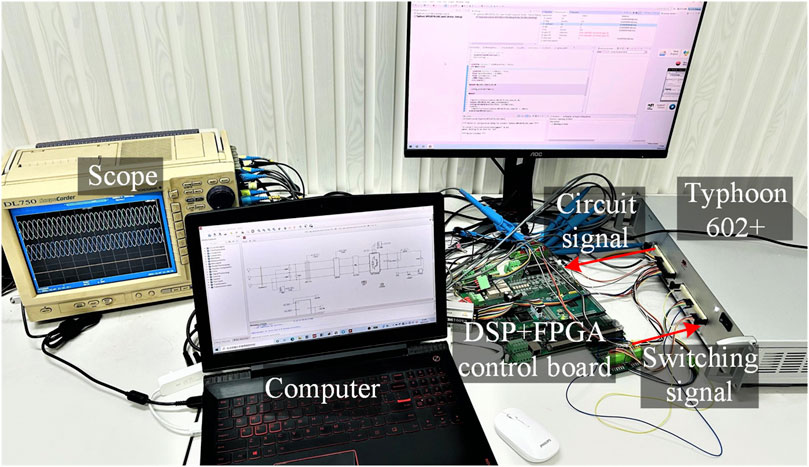
Figure 3. Hardware platform of the CHIL experiment.
The experimental results using the above parameters are shown in Figure 4A. The figure sequentially shows the waveforms of the grid line voltage Ugab, d-axis current Id, q-axis current Iq, phase error δ, and PLL frequency fpll. When the grid voltage drops from 1.0 p.u. to 0.05 p.u., the current reference switches quickly. The active current reference Idref switches from 1.0 p.u. to 0, while the reactive current reference Iqref switches from 0 to −1 p.u. As the steady-state operating point changes, the system enters the transient synchronization process. During this process, the reactive current quickly tracks its reference and stabilizes at −1 p.u., while the active current undergoes a dynamic decay process of over 100 ms. As a result, the system maintains synchronicity with the grid, which is consistent with the theoretical analysis and simulation results.
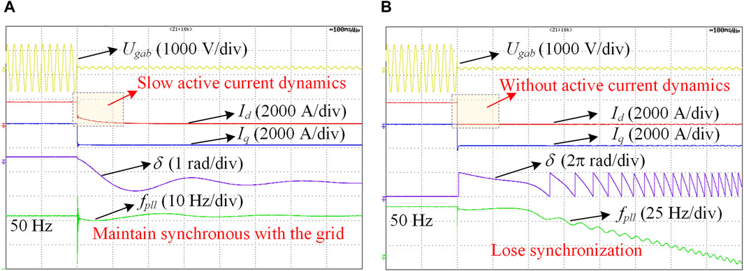
Figure 4. Experimental results. (A) With slow active current dynamics and (B) without active current dynamics.
Increasing kic can increase the absolute value of the dominant pole p2, thereby accelerating the active current dynamics. In this case, the experimental results are shown in Figure 4B. Both active and reactive current can quickly track their references. However, without slow active current dynamics, the PLL frequency decreases continuously, and a loss of synchronization occurs. The experimental results demonstrate that the active current dynamics have a non-negligible impact on the transient stability of GFL converters.
6 Conclusion
This article discusses the intrinsic mechanism of why active current cannot track its reference quickly during severe grid faults. The transfer function from grid voltage disturbance to current output has a zero located at the origin and a dominant pole, resulting in a slow dynamic response. In addition, severe grid faults have a much greater impact on active current dynamics than reactive current dynamics. Therefore, active current will undergo obvious dynamic attenuation during severe grid faults. The coupling of active current dynamics and the grid impedance generates a transient voltage that affects the transient synchronization process. Accordingly, a refined third-order transient synchronization model is established, which offers a more accurate assessment of the transient stability of GFL converters during severe grid faults than the conventional second-order model.
Data availability statement
The raw data supporting the conclusion of this article will be made available by the authors, without undue reservation.
Author contributions
CW: validation, methodology, supervision, conceptualization, and writing–review and editing. ZH: software, investigation, and writing–original draft. YW: validation, supervision, and writing–review and editing. FB: supervision and writing–review and editing.
Funding
The author(s) declare that financial support was received for the research, authorship, and/or publication of this article. This work is supported by the National Natural Science Foundation of China under Grant 52207063.
Conflict of interest
The authors declare that the research was conducted in the absence of any commercial or financial relationships that could be construed as a potential conflict of interest.
Publisher’s note
All claims expressed in this article are solely those of the authors and do not necessarily represent those of their affiliated organizations, or those of the publisher, the editors, and the reviewers. Any product that may be evaluated in this article, or claim that may be made by its manufacturer, is not guaranteed or endorsed by the publisher.
References
Chen, J., Liu, M., O’Donnell, T., and Milano, F. (2020). Impact of current transients on the synchronization stability assessment of grid-feeding converters. IEEE Trans. Power Syst. 35, 4131–4134. doi:10.1109/tpwrs.2020.3009858
Göksu, Ö., Teodorescu, R., Bak, C. L., Iov, F., and Kjær, P. C. (2014). Instability of wind turbine converters during current injection to low voltage grid faults and PLL frequency based stability solution. IEEE Trans. Power Syst. 29, 1683–1691. doi:10.1109/tpwrs.2013.2295261
He, X., Geng, H., Xi, J., and Guerrero, J. M. (2021). Resynchronization analysis and improvement of grid-connected VSCs during grid faults. IEEE J. Emerg. Sel. Top. Power Electron. 9, 438–450. doi:10.1109/jestpe.2019.2954555
Hu, Q., Fu, L., Ma, F., Ji, F., and Zhang, Y. (2021). Analogized synchronous-generator model of PLL-based VSC and transient synchronizing stability of converter dominated power system. IEEE Trans. Sustain. Energy. 12, 1174–1185. doi:10.1109/tste.2020.3037155
Tian, Z., Tang, Y., Zha, X., Sun, J., Huang, M., Fu, X., et al. (2022). Hamilton-based stability criterion and attraction region estimation for grid-tied inverters under large-signal disturbances. IEEE J. Emerg. Sel. Top. Power Electron. 10, 413–423. doi:10.1109/jestpe.2021.3076189
Wu, C., Lyu, Y., Wang, Y., and Blaabjerg, F. (2024). Transient synchronization stability analysis of grid-following converter considering the coupling effect of current loop and phase locked loop. IEEE Trans. Energy Convers. 39, 544–554. doi:10.1109/tec.2023.3314095
Wu, H., and Wang, X. (2020). Design-oriented transient stability analysis of PLL-synchronized voltage-source converters. IEEE Trans. Power Electron. 35, 3573–3589. doi:10.1109/tpel.2019.2937942
Xiong, L., Liu, X., Zhao, C., and Zhuo, F. (2020). A fast and robust real-time detection algorithm of decaying DC transient and harmonic components in three-phase systems. IEEE Trans. Power Electron. 35, 3332–3336. doi:10.1109/tpel.2019.2940891
Keywords: grid-following converter, severe grid fault, transient stability, active current dynamic, phase-locked loop
Citation: Wu C, Huang Z, Wang Y and Blaabjerg F (2024) A new transient phenomenon caused by active current dynamics of grid-following converters during severe grid faults. Front. Energy Res. 12:1425105. doi: 10.3389/fenrg.2024.1425105
Received: 29 April 2024; Accepted: 04 June 2024;
Published: 09 July 2024.
Edited by:
Liansong Xiong, Xi’an Jiaotong University, ChinaReviewed by:
Xiaokang Liu, Polytechnic University of Milan, ItalyMeng Chen, University of Cambridge, United Kingdom
Yonghui Liu, Hong Kong Polytechnic University, Hong Kong, SAR China
Copyright © 2024 Wu, Huang, Wang and Blaabjerg. This is an open-access article distributed under the terms of the Creative Commons Attribution License (CC BY). The use, distribution or reproduction in other forums is permitted, provided the original author(s) and the copyright owner(s) are credited and that the original publication in this journal is cited, in accordance with accepted academic practice. No use, distribution or reproduction is permitted which does not comply with these terms.
*Correspondence: Chao Wu, d3VjaGFvQHNqdHUuZWR1LmNu