- Zhongshan Power Supply Bureau of Guangdong Power Grid Co., Ltd., Zhongshan, China
In order to further control harmonic current in distribution network, a LCL APF control strategy based on model predictive control is proposed. Firstly, APF mathematical model is established. Then, a multi-objective optimization model predictive control strategy (MPC) is proposed, which comprehensively considers the performance of AC side and DC side of APF. This strategy solves the delay problem existing in the existing MPC strategy: while improving the performance of APF, there is no need to set weight factor; Then, Kalman filter is used to predict the inverter current, thus simplifying the APF measurement system. Finally, the simulation results show that the proposed control strategy can simplify the measurement system and make APF have stronger harmonic suppression ability when it only participates in power conversion and better active filter performance when it participates in harmonic control.
1 Introduction
With the continuous progress of power electronic technology, a large number of power electronic devices have been applied to the source, network, load and storage of power system, which not only improves the operation and control flexibility of power system, but also brings the problem of broadband harmonics of power grid (Shi et al., 2020). On the one hand, the power electronic device itself constitutes a harmonic source, and its internal power semiconductor switching action will bring considerable high-frequency harmonics; On the other hand, the mechanism of harmonic transmission and evolution is more complex due to the interaction between devices, which shows the characteristics of wide area and wide frequency (Xiong et al., 2021). The existence of harmonics will lead to the deterioration of power quality, accelerated aging of equipment, interference in measurement communication and other problems, which must be suppressed (Liu et al., 2023).
At the distribution network level, passive filters are commonly used to achieve harmonic control (Xie et al., 2013), but passive filters are usually configured in band-stop mode and have limited frequency bands, which is difficult to meet the challenge of harmonic broadband. The active power filter (APF) based on power electronics technology has the characteristics of flexible operation control and can realize the tracking and compensation of dynamic harmonics, and the filter bandwidth is high, which has attracted much attention in recent years (Xiong et al., 2020). However, due to the high cost of APF, it has not been widely promoted and applied. At the hardware level, the circuit structure of APF is a three-phase voltage source rectifier/inverter, which is the same as the grid-connected converter structure in other devices such as new energy units and electric vehicle charging facilities. Therefore, in recent years, many scholars have proposed to use three-phase grid-connected inverters as active filters (APF) to participate in harmonic governance (L. Yang et al., 2020). However, there is still room for improvement in performance: 1) Absorb harmonic current in distribution network as much as possible; 2) At the same time, ensure that no new harmonic current is introduced. The high performance APF control strategy needs to be further studied.
However, because the grid-connected converter is designed to realize the power conversion of the frequency segment, the control structure and strategy used are difficult to meet the functional requirements of APF (Xiong et al., 2016). The double closed-loop linear control strategy usually adopted by grid-connected converters has limited bandwidth, and the current control bandwidth is generally set at 300 Hz, which makes it difficult to track and adjust the current harmonics of higher frequencies (Cheng et al., 2017). Therefore, nonlinear control strategies such as repetitive control, sliding mode control and model predictive control with faster dynamic response and stronger tracking performance are more suitable. The repetitive control that accumulates the error to the output signal period by period has good steady-state performance, but the embedded delay link causes the output current to lag the reference value by one power frequency cycle (Liang et al., 2018). Although the addition of proportional integration can effectively improve the dynamic performance of repetitive control, the complex compensation function makes it difficult to implement in engineering applications (Zhang et al., 2014). The sliding mode control with error switching function as the core has a large current control bandwidth, which can ensure that the electrical volume in APF converges to the balance point error determined by the output current reference value (Guo et al., 2022). However, because the system will jitter near the preset sliding mode state, additional output current will be chattered, which will affect the control accuracy and stability of the system and increase the energy loss (Li and Hong, 2012). Finite set Model Predictive Control (MPC) is good at solving nonlinear control problems by selecting the optimal switching state through traversal algorithm. With the progress of computing power of embedded control chip, it effectively compensates for the defect of large calculation amount of MPC, so it has been applied more and more in power electronic device control (Falkowski and Sikorski, 2018; Zhang et al., 2023). For grid-connected converters, in order to overcome the problem that MPC method cannot directly control the current on the grid side of LCL filter (Zhang et al., 2022), the traditional MPC strategy introduces damping ratio to calculate the corresponding current reference value on the inverter side, but the control effect of the current on the grid side is poor (Chico-Villegas et al., 2023). In recent years, two new MPC strategies have emerged: 1) The optimal switching combination3 (PCi1i2uc) is selected by predicting the current on the grid side, the current on the inverter side and the filter capacitance voltage at the next time according to the equation of state of LCL-type APF (Falkowski and Sikorski, 2018). 2) On this basis, the state equation is used to predict two steps, and then the optimal switch combination is selected. Longer prediction steps can obtain higher control accuracy, but correspondingly the calculation steps are more complicated and the calculation amount is larger (PCi1i2uc-2steps) (Falkowski and Sikorski, 2018). The above two have defects: 1) In the process of deriving the current reference value of the inverter side and the capacitor voltage reference value from the current reference value of the grid side, the delay problem under the discrete control system is ignored, resulting in the deterioration of the control performance of the current on the grid side; 2) In order to make up for this defect, two more items are added to the value function for correction, thus introducing weight factors that need to be artificially set. The selection of factors has a great impact on APF performance, but it can only rely on experience value, which is not reliable; 3) The premise of using the equation of state is to measure all variables involved in the equation, resulting in a complex measurement system.
Faced with the complex measurement system of APF, some scholars use extended state observer to reduce the impact of measurement errors (Zheng et al., 2023), or adopt periodic model parameter adjustment strategy to correct device parameter errors (Xie et al., 2021), but it is still necessary to sample up to 11 electrical volumes. The Kalman filter can reduce the measurement sensor and reduce the hardware cost while ensuring the measurement accuracy. At present, this method has been applied to the control of modular multilevel converters (Pizarro et al., 2023). This method can be applied to APF control for reference.
To solve these problems, this paper proposes a LCL APF control strategy based on model predictive control.By analyzing the LCL-type APF mathematical model, the multi-objective optimization model predictive control strategy considering the time delay problem of discrete systems is established. The Kalman filter is used to predict the APF inverter current, thus simplifying the measurement system.
2 APF mathematical model
2.1 Analytic relationship on the AC side
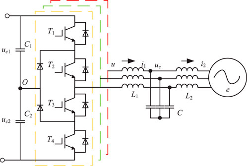
Figure 1 shows the main circuit topology of APF. APF connects capacitors C1 and C2 with voltages uC1 and uC2 respectively in series to provide DC voltage VDC with O as the neutral point on the DC side. The LCL filter composed of inductor L1 on the inverter side, filter capacitor C and inductor L2 on the grid side is connected to the system containing power supply, line and load.
After the Parker transformation, ud, uq is the direct axis component of the inverter voltage. i1d, i1q are the direct axis and quadrature axis components of the inverter side current. i2d and i2q are the direct axis components of the current on the network side. ucd and ucq are the direct axis and cross-axis components of the filter capacitor voltage. ed, eq are the direct axis quadrature axis components of APF network side voltage; The positive direction of the signal is shown by the arrow in the figure. According to Kirchhoff’s law, the electric volume on the AC side has the following relationship in the dq rotating coordinate system:
where, ω is the angular velocity corresponding to the system frequency, i1 = [i1d i1q]T, i2 = [i2d i2q]T, uc = [ucd ucq]T, u = [ud uq]T, e = [ed eq]T, respectively, are the direct axis component and the quadrative axis component of the corresponding electrical volume. In order to discretize Equations 1–3, the forward difference method is used for any electrical quantity x as shown in Equation 4.
where, Ts is the period corresponding to the switching frequency. The spatial state equation of APF under the dq coordinate axis after discretization is shown in Equations 5–9.
The formula shows that at the time k+1, the state variable x (k+1), which consists of the inverter side current, filter capacitor voltage and network side current, is determined by the state variable x(k) at the time k, the input state u(k) and the interference quantity e(k). Where A is the state matrix and B is the input matrix.
2.2 Analytic relationship on the DC side
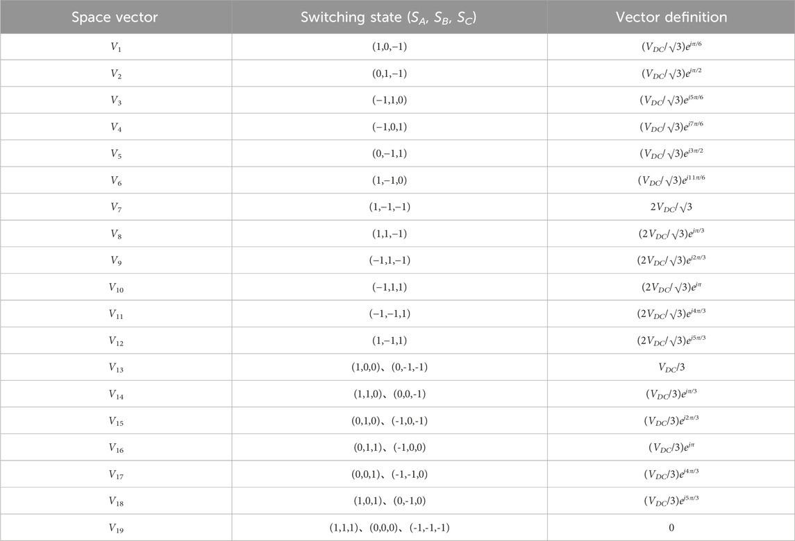
APF adopts the neutral point clamp (NPC) topology that can output three levels. The output voltage of any phase can be described by the switching state function Sx (x = a, b, c) as shown in Equation 10. Take phase A as an example: when Sa = 1, switch tubes T1 and T2 are on, T3 and T4 are off, ua = VDC/2; when Sa = 0, T2 and T3 are on, T1 and T4 are off, ua = 0. When Sa = −1, T3 and T4 are on, T1 and T2 are off, and ua = −VDC/2.
As shown in Table 1, considering ABC three-phase, there are 27 kinds of switch combinations in APF, constituting 19 kinds of vector states.
Among them, V1 ∼ V6 are large vectors, V7 ∼ V12 are medium vectors, and each vector only corresponds to one type of switch combination. V13 ∼ V18 are small vectors, and each small vector has positive and negative switching combinations, respectively called positive small vector and negative small vector. The zero vector V18 corresponds to three switching states. In order to avoid a series of problems such as damage to the switching device due to excessive pressure, it is necessary to maintain the neutral point balance, that is, the upper and lower capacitor voltage difference Δuo = uC1-uC2 on the DC side is about 0. The direction and magnitude of the neutral current can be controlled by adjusting the action time of the positive and negative small vectors with redundant relationship, so as to achieve the upper and lower capacitor voltage balance on the DC side (Liu et al., 2018) as shown in Equations 11, 12.
3 Model predictive control strategy considering multi-objective optimization
The MPC algorithm can control multiple variables at the same time only through a single value function, and the proposed strategy is realized: on the AC side, the control i2 outputs according to the given current command value i2*; on the DC side, the maintenance Δuo is about 0.
By type (5)–(8), u (k + 1) only can directly control i1 (k + 2), and indirectly affect the uc (k + 3) and i2 (k + 4). To track the output of i2*, i2* can be used to calculate the current reference value i1* on the inverter side, and then select the optimal switch combination u (k + 1). In the case of discrete system control delay, the calculation process is as follows:
1) The reference values also follow the mathematical relationship of Equations 5–8, and the Equations 13, 14 can be obtained by a certain transformation, and the reference value of the filter capacitor voltage uc*(k + 3) at k + 3 can be calculated. Considering that the grid voltage changes slowly on the time scale of the switching frequency, if TS is small enough, the sampling value e(k) at the current time k can replace the sampling value e (k + 3) at the future time. Similarly, uc*(k + 2) can be calculated according to Equations 15, 16. Then, based on uc*(k + 3) and uc*(k + 2), the reference value i1*(k + 1) of the inverter current at k + 1 is calculated according to Equations 17, 18, which is also obtained by the transformation of Equations 5–8.
2) Based on u (k + 1), the corresponding i1 (k + 2) can be predicted. The value function f1, which represents the future error of i1, is calculated according to Equation 19.
Go through 19 vector states and select the u (k+1) that minimizes f1. Equations 13–18 shows that when the switch combination makes f1 the lowest, the difference between the actual output network current and i2* can be minimized, and the resonance can be suppressed.
3) If u (k + 1) belongs to large vector or medium vector, corresponding switch combinations Sa (k + 1), Sb (k + 1), Sc (k + 1) can be obtained directly. If u (k + 1) belongs to the zero vector, set Sa (k + 1) = 0, Sb (k + 1) = 0, Sc (k + 1) = 0. If u (k + 1) is a small vector, the value function f2 that characterizes the future size of Δuo is calculated according to Equation 20.
Select Sa (k + 1), Sb (k + 1), Sc (k + 1) from the positive and negative small vectors that make f2 take a smaller value.
4) Continue to cycle steps 1)∼3), so that i2 follows the output of i2*, and maintains Δuo in a small range.
4 Inverter side current prediction method based on Kalman filter
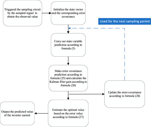
According to the electric quantity relationship of AC side in Equations 5–8, the current value of inverter side can be derived by using the current of grid side and the filter capacitor voltage. Therefore, the measurement system can be simplified to measure only i2 and uc to make real-time closed-loop prediction of i1, eliminating part of the current sensor structure. Specifically, measurement i2 and uc constitute measurement matrix z(k), as defined in Equations 22, 23. Real-time prediction of i1 is performed based on Kalman filter state observer. As a closed-loop prediction scheme with strong adaptability to the system, Kalman filter algorithm can extract the estimator information from the measurement information to obtain the online estimate, which has a significant advantage in eliminating the impact of measurement noise caused by the sensor. The steps to build a Kalman filter state observer are as follows:
Firstly, the Kalman filter state observation equation is established on the basis of Equation 5:
where, z(k) is the output matrix of the state observer at k time; H is the observation matrix; R is the state noise variance matrix, and Q is the measurement noise variance matrix. A prior estimate x-(k) of the state variable can be calculated by Equation 21. According to Equations 24–28, the error between x-(k) and the actual value x(k) is defined as the prior error e-(k), and the covariance of e-(k) is the prior error matrix P-(k). In the actual calculation, e-(k) is unknown, so the posterior error matrix P(k) at k-1 time is needed to calculate.
Then, combining H and P-(k), the Kalman filter gain matrix K(k) is obtained.
Based on K(k) and observation matrix z(k), the posterior estimator xkal(k) can be obtained by modifying x-(k).
In order to continuously update the covariance p-(k) of the prior estimate, a posterior error matrix is calculated after modifying the state variable:
Where I is the identity matrix.
The specific operation flow chart of Kalman filtering is shown in Figure 2:
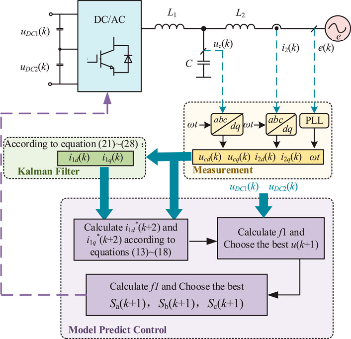
To sum up, the overall control strategy of the strategy proposed in this paper is shown in Figure 3:
(1) Input uc and i2 sampling values to Kalman filter to obtain real-time closed-loop prediction value of i1;
(2) The optimal switch combination is calculated based on model predictive control considering multiple objectives.
5 Simulation
5.1 Simulation parameter
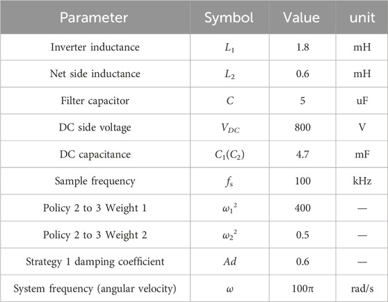
Through modeling and simulation in Matlab/Simulink, it is verified that the proposed strategy can accurately predict the inverter current and effectively suppress the neutral voltage deviation. The active filtering performance of the proposed method is compared with the PC-iAD method in reference (Chico-Villegas et al., 2023), and the PC-i1i2uc and PCi1i2uc-2steps in reference (Falkowski and Sikorski, 2018) (referred to as strategies 1, 2, and 3, respectively). Device parameters and control parameters are shown in Table 2. In particular, in order to simulate the voltage and current sensor errors in the actual device, the measurement errors of uc, i2 and e are set to ±0.5 V, ±0.5 V, and ±0.2A respectively in the simulation.
5.2 APF is only involved in electrical energy conversion
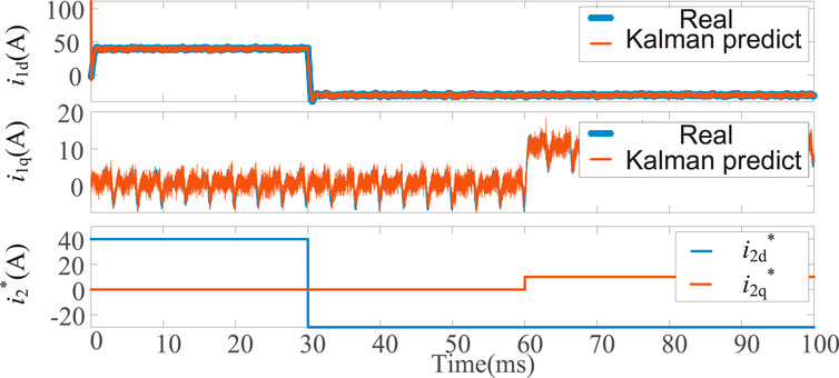
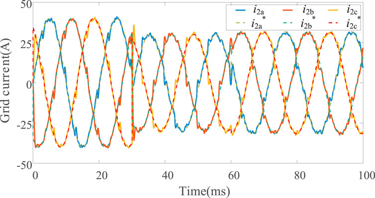
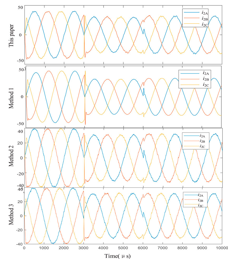
The basic function of APF is to participate in electric energy conversion and realize inverter or rectification. For this reason, the D-axis reference value of the current at the network side is set to 40A at the beginning, and the step changes to −30A after 0.03 s. The reference value of the q axis is initially 0A, and the step transition after 0.06 s is 10A. Comparing the control strategies proposed in this paper with strategies 1, 2, and 3, the control effects of the four control strategies only participate in electric energy conversion.
Firstly, it is verified that the proposed strategy can accurately predict the inverter current. As shown in Figure 4, when i2d* is constant and unchanged, the predicted value of Kalman filter is basically similar to the actual value for the D-axis component of the current on the inverter side, and the error is about ± 2A. After the mutation of i2d*, the error between the predicted value and the actual value can reach 10A, but the process only lasts tens of microseconds and ends. Similarly, for the Q-axis component of the current on the inverter side, the predicted value of Kalman filter is basically consistent with the actual value.
Converted back to the stationary three-phase coordinate system, the mean square error of the current prediction error on the inverter side of phase A, B and C is 0.93A, 0.92A, and 0.93A, respectively, and the error is all within 2%. Obviously, Kalman filter can accurately predict the inverter current. And as shown in Figure 5, the current on the network side can be accurately and quickly output following the reference value. Therefore, the inverter side current sensor can be omitted, thus simplifying the measurement system.
Secondly, it is verified that the proposed strategy can effectively inhibit Δuo. As shown in Figure 6, although Δuo fluctuates, it can always be maintained in the range of [−4V, 4V], and the deviation is only 1.5% of the capacitor voltage.
Finally, the output effect of APF side current is considered. As shown in Figure 7, the current waveforms of the four strategies at the network side are basically the same, and the total harmonic distortion (THD) of the four strategies within 80 ms–100 ms is also 1.26%, showing similar performance.
5.3 APF participates in harmonic control
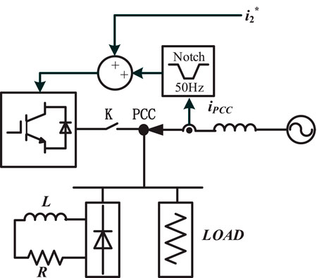
The common application scenario is shown in Figure 8. The APF is connected to the connecting point (PCC) after the switch K, and is in parallel with the load containing nonlinear components. In this paper, the load inductor of the rectifier is 2 mH, and the load resistance of the rectifier is 5Ω. APF needs to cooperate with the distribution network to provide fundamental current for the load, so set i2d* to 30A and i2q* to 0A. At the same time, APF should actively filter out the harmonic current in the distribution network. To this end, additional sampling of the current ipcc flowing from the distribution network into the PCC point is needed, and the harmonic component is obtained through the 50 Hz notch, which is added as the grid side current command, and the harmonic current similar to the rectifier is output, thus reducing THD (ipcc) to achieve active filtering.
As shown in Figure 9A, before APF participated in harmonic control, the existence of nonlinear loads caused a large amount of harmonic current in ipcc: THD was about 15%. As shown in Figures 9B–E, after adopting the proposed strategy in this paper, the harmonic control effect of APF is the best: THD decreases by 10.60% compared with that before treatment; THD decreased by 10.33% compared with method 1. Compared with method 2, THD decreased by 0.63%. THD decreased by 0.39% compared with method 3.
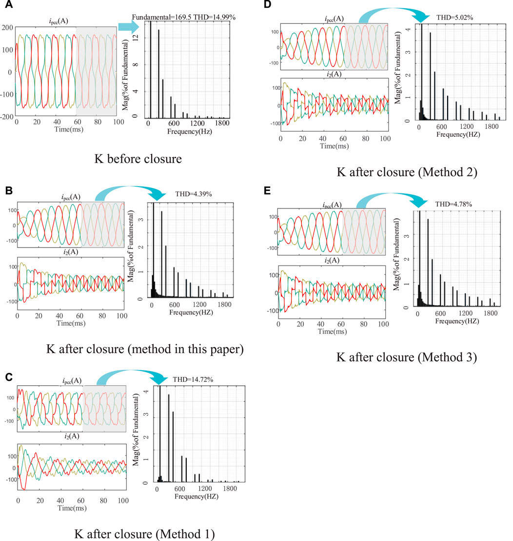
Figure 9. Harmonic analysis diagram. (A) K before closure, (B) K after closure (method in this paper), (C) K after closure (Method 1), (D) K after closure (Method 2), (E) K after closure (Method 3).
5.4 Sensitivity analysis
Considering that the sampling delay caused by analog-to-digital conversion and signal filtering processing is 1/fs, the performance of THD (i2) and THD (ipcc) in the two scenarios becomes 1.3% and 4.56% respectively, which still has a good performance.
The performance of the proposed method at different switching frequencies is listed in Table 3. Although the performance of the proposed method decreases with the decrease of switching frequency in both scenarios, it still maintains a high level. It can be seen that the switching frequency band adapted by the proposed method is relatively wide.
6 Conclusion
Based on the discrete mathematical model of LCL APF, this paper proposes a control strategy of LCL APF based on model predictive control, which can solve the delay problem caused by LCL filter. Combined with Kalman filter, the APF performance can still be improved under the condition of simplifying the measurement system. Simulation verification is as follows:
1) Kalman filter can accurately predict the APF inverter current, and the error is less than 2%. After the predicted value is used, the current on the network side can change accurately and quickly with the reference value. Therefore, it can save the current sensor and simplify the measurement system.
2) The newly proposed MPC strategy improves the performance of APF: THD decreases by about 10% compared with that before treatment. It can also achieve lower THD than existing MPC strategies. This strategy does not need to change the weight factor according to the device parameters, so it is easy to use.
The control method proposed in this paper is verified by Matlab/Simulink simulation. There are stray parameters in the power device in the actual device, and the sampling and calculation delay also affect the control performance. Therefore, the next step is to build a physical platform to further test the proposed method.
Data availability statement
The original contributions presented in the study are included in the article/Supplementary Material, further inquiries can be directed to the corresponding author.
Author contributions
SJ: Writing–original draft, Writing–review and editing. LD: Writing–original draft, Writing–review and editing. YL: Writing–original draft, Writing–review and editing. LY: Writing–original draft, Writing–review and editing. BL: Writing–original draft, Writing–review and editing.
Funding
The author(s) declare that financial support was received for the research, authorship, and/or publication of this article. This research was funded by China Southern Power Grid Corporation Science and Technology Project under Grant 032000KK52222025.
Conflict of interest
Authors SJ, LD, YL, LY, and BL were employed by Zhongshan Power Supply Bureau of Guangdong Power Grid Co., Ltd.
Publisher’s note
All claims expressed in this article are solely those of the authors and do not necessarily represent those of their affiliated organizations, or those of the publisher, the editors and the reviewers. Any product that may be evaluated in this article, or claim that may be made by its manufacturer, is not guaranteed or endorsed by the publisher.
References
Cheng, N., Wang, Y., and Lei, W. (2017). Resonance characteristics of multiple converters in parallel and optimal virtual damping method. Proc. CSEE 37 (05), 1467–1478. doi:10.13334/j.0258-8013.pcsee.160216
Chico-Villegas, J.-P., Guzman, R., de Vicuña, L. G., Miret, J., Castilla, M., and Komurcugil, H. (2023) “Model predictive control for an LCL voltage source inverter with active damping capability and current limitation,” in IECON 2023- 49th Annual Conference of the IEEE Industrial Electronics Society, Singapore, October 19, 2023, 1–5. doi:10.1109/IECON51785.2023.10312716
Falkowski, P., and Sikorski, A. (2018). Finite control set model predictive control for grid-connected AC–DC converters with LCL filter. IEEE Trans. Industrial Electron. 65 (4), 2844–2852. doi:10.1109/TIE.2017.2750627
Guo, L., Zheng, M., Li, Y., Zhu, H., and Jin, N. (2022). Parametric sliding mode predictive control strategy for three-phase LCL grid-connected inverter. Power Syst. Prot. Control 50 (18), 72–82. doi:10.19783/j.cnki.pspc.211576
Li, J., and Hong, Z. (2012). Sliding mode variable structure control of three phase photovoltaic grid-connected system. Power Syst. Prot. Control 40 (12), 83–87.
Liang, G., Xu, J., and Wang, Y. (2018). Research on three-level modular intelligent power quality compensation device. Adv. Technol. Electr. Eng. Energy 37 (05), 45–50.
Liu, W., Lv, Z., and Liu, H. (2023). A review of the development of form and operation control technology of electric power distribution area. Proc. CSEE 43 (13), 4899–4922. doi:10.13334/j.0258-8013.pcsee.220890
Liu, Y., Hu, C., Ma, D., and Chen, Q. (2018). Three-level ANPC converter midpoint voltage balance MPC. Power Electron. 52 (8), 110–113.
Pérez-Estévez, D., and Doval-Gandoy, J. (2020). A finite-control-set linear current controller with fast transient response and low switching frequency for grid-tied inverters. IEEE Trans. Industry Appl. 56 (6), 6546–6564. doi:10.1109/TIA.2020.3012923
Pizarro, G., Poblete, P., Droguett, G., Pereda, J., and Núñez, F. (2023). Extended kalman filtering for full-state estimation and sensor reduction in modular multilevel converters. IEEE Trans. Industrial Electron. 70 (2), 1927–1938. doi:10.1109/TIE.2022.3165286
Shi, L., Jia, Q., and Lin, L. (2020). Global optimal governance strategy of harmonic distribution in electronic power distribution network. Proc. CSEE 40 (09), 2914–2924. doi:10.13334/j.0258-8013.pcsee.191844
Xie, H., Wang, K., and Jiang, Z. (2013). Optimization design of passive filter banks based on three-point working condition. Power Syst. Technol. 37 (06), 1713–1718. doi:10.13335/j.1000-3673.pst.2013.06.008
Xie, Y., Liu, L., and Guan, Y. (2021). Adaptive model predictive control strategy for three-phase LCL grid-connected inverter. Electr. Mach. Control 25 (4), 40–51. doi:10.15938/j.emc.2021.04.006
Xiong, L., Liu, X., Zhang, D., and Liu, Y. (2021). Rapid power compensation-based frequency response strategy for low-inertia power systems. IEEE J. Emerg. Sel. Top. Power Electron. 9 (4), 4500–4513. doi:10.1109/JESTPE.2020.3032063
Xiong, L., Liu, X., Zhao, C., and Zhuo, F. (2020). A fast and robust real-time detection algorithm of decaying DC transient and harmonic components in three-phase systems. IEEE Trans. Power Electron. 35 (4), 3332–3336. doi:10.1109/TPEL.2019.2940891
Xiong, L., Zhuo, F., Wang, F., Liu, X., Chen, Y., Zhu, M., et al. (2016). Static synchronous generator model: a new perspective to investigate dynamic characteristics and stability issues of grid-tied pwm inverter. IEEE Trans. Power Electron. 31 (9), 6264–6280. doi:10.1109/TPEL.2015.2498933
Yang, L., Yang, J., Gao, M., Chen, Y., and Zhang, X. (2020). A systematic approach via IIR filters for enhancing the robustness of LCL-type shunt active power filters to grid impedance. IEEE Trans. Industry Appl. 56 (5), 5095–5107. doi:10.1109/TIA.2020.2999273
Zhang, B., Wu, W., Yang, Y., Gao, N., Chen, J., Koutroulis, E. G., et al. (2023). A novel simplified finite control set repeat model predictive control for grid-connected inverters. IEEE Trans. Industrial Electron. 70 (11), 11324–11333. doi:10.1109/TIE.2022.3231252
Zhang, B., Wu, W., Gao, N., Koutroulis, E., Chen, J., Lu, G., et al. (2022) “An improved DBC-MPC strategy for LCL-filtered grid-connected inverters,” in IECON 2022 – 48th Annual Conference of the IEEE Industrial Electronics Society, Brussels, Belgium, October 20, 2022, 1–6. doi:10.1109/IECON49645.2022.9968666
Zhang, X., Wang, Y., and Yu, C. (2014). Improved repetitive control strategy for LCL grid-connected inverter. Automation Electr. Power Syst. 38 (20), 101–107.
Keywords: LCL filter, active filter, finite set model predictive control, Kalman filtering, harmonic control
Citation: Jiang S, Du L, Li Y, Yang L and Luo B (2024) LCL APF control strategy based on model predictive control. Front. Energy Res. 12:1423199. doi: 10.3389/fenrg.2024.1423199
Received: 25 April 2024; Accepted: 25 June 2024;
Published: 06 November 2024.
Edited by:
Haitao Zhang, Xi’an Jiaotong University, ChinaReviewed by:
Chunyang Liu, Shandong University, ChinaJiaxing Lei, Southeast University, China
Shenquan Liu, South China University of Technology, China
Copyright © 2024 Jiang, Du, Li, Yang and Luo. This is an open-access article distributed under the terms of the Creative Commons Attribution License (CC BY). The use, distribution or reproduction in other forums is permitted, provided the original author(s) and the copyright owner(s) are credited and that the original publication in this journal is cited, in accordance with accepted academic practice. No use, distribution or reproduction is permitted which does not comply with these terms.
*Correspondence: Shaoyan Jiang, amlhbmdzaGFveWFuX2NzZ0AxNjMuY29t
 Shaoyan Jiang
 Lifeng Du