 Guojiang Zhang
 Jingbo Zhao
 Yongyong Jia
- Research Institute, State Grid Jiangsu Electric Power Co., Ltd., Nanjing, China
Harmonics are an important cause of voltage distortion, and voltage reduction and voltage distortion are the main causes of commutation failure. But most of the current research studies on commutation failure are based on the drop in fundamental voltage after a fault, and there are few reports on the impact of voltage distortion on commutation failure. Aiming to solve the above problem, this article first analyzes the generation and transmission characteristics of harmonics in AC and DC systems, as well as the coupling degree of harmonics in DC systems. Then, starting from the mechanism of the commutation process, a commutation failure analysis method based on the harmonic voltage time area is proposed. This method can quantitatively analyze the impact of different harmonics on commutation failure. On this basis, the harmonic criteria for causing commutation failure are established, and the harmonic characteristics of AC voltage when harmonics cause subsequent commutation failure are quantitatively analyzed. Finally, a preventive controller is proposed to suppress commutation failure caused by different harmonics, where the above analysis is verified by the simulations.
1 Introduction
DC transmission has the advantages of strong controllability, large transmission capacity, and low transmission loss (Jiang et al., 2022; Tao et al., 2020). It is widely used in long-distance power transmission, underground and submarine cable power transmission, and asynchronous power grid networking (Taherzadeh et al., 2023) (Jiang et al., 2023). It has high economic and social benefits (Song et al., 2023). If supported by a “strong AC” power grid, the High Voltage Direct Current transmission system can efficiently deliver power from traditional energy and renewable energy bases to load centers (Shu et al., 2023).
DC transmission composed of thyristors is prone to commutation failure, which is one of the most common faults in traditional HVDC systems (Ouyang et al., 2023). Commutation failure is less likely to occur on the rectifier side because the trigger angle of the rectifier valve is larger and has a longer time for commutation. Therefore, the cause of commutation failure on the rectifier side is generally just a trigger circuit failure. Most commutation failures in DC systems occur on the inverter side (Su et al., 2024). The main causes of commutation failure in HVDC systems are as follows:
1) AC system faults cause the inverter AC line voltage amplitude to decrease, and asymmetric faults cause the commutation voltage phase angle to drift;
2) DC current increases significantly;
3) The setting value of the triggering angle or arc extinction angle in the DC system control link is set too small;
4) Internal failure of the converter. For example, the converter valve misconducts, triggers circuit failure, and triggers pulse loss;
5) Severe distortion of the commutation voltage caused by harmonics;
6) The access to distributed new energy sources reduces system intensity and increases the risk of commutation failure.
Current research on commutation failure focuses on the mechanism and criteria of commutation failure, the impact on the AC system, and prevention control and recovery strategies.
Commutation failure will cause the system voltage to decrease and the DC current to increase for a short time. During the commutation failure process, the DC power and voltage will change drastically, causing an impact on the AC systems on both sides of the DC. Multiple consecutive commutation failures will cause the DC system to lockout [28]. Jiang et al. (2022) focused on the phenomenon of sub-synchronous oscillation caused by HVDC. A detailed analysis of the current replacement law after commutation failure pointed out that this characteristic will excite higher-amplitude shaft torsional vibration, thereby increasing the risk of sub-synchronous oscillation of the system. With the development of my country’s China UHVDC transmission technology, the power transmitted by single-circuit DC is increasing, and the impact of commutation failure on the connected AC system is also increasing.
Jingzhe et al. (2015) equated the sending and receiving ends into two groups of generators, analyzed the impact of multiple DC commutation failures on the stability of the sending end under different working conditions based on the equal-area rule and the generator rotor motion equation, and pointed out that the sending end power and the angular stability characteristics are related to the energy accumulated when multiple DC commutations fail simultaneously. Tu et al. (2017) extended the two-machine system at the sending end to three machines and derived the rotor motion equation of the three-machine system. Then, based on the decoupling analysis between the inherent period proportional multi-stability modes of different stability modes of the sending-end system, the effects of the commutation failure form and the unit's rotational inertia on the system stability under different stability modes were further analyzed, and simulation calculations were performed under stability limits under different faults in different operating modes in the Sanhua power grid.
The above studies combine commutation failure with actual operating characteristics and working conditions and are mostly based on simulation analysis, lacking strict theoretical derivation and proof. In response to the transient overvoltage problem caused by DC commutation failure or blocking, ElMehdi et al. (2014) considered the impact of transient overvoltage on wind farms and analyzed the determinants of reactive power compensation capacity of high-voltage DC systems and the dynamics of different reactive power compensation devices. Krishayya et al. (1997) analyzed the relationship between short-circuit ratio and transient overvoltage and provided reference values of transient overvoltage according to different system strengths. However, the equivalent value of the AC system voltage source and the transient process are not considered in the modeling process. Davies (2008) simulated and analyzed the impact of multi-infeed effective short-circuit ratio, commutation reactance, etc., on the most serious transient overvoltage under complete DC blocking. Combined with the simulation analysis of transient overvoltage of DC systems in Canada, Norway, and other regions, it was pointed out that further research requires the establishment of more precise mathematical models. Wang et al. (2012) extended the definition of multi-feed reactive power effective short-circuit ratio based on the study by Davies (2008) and simulated and qualitatively analyzed the relationship between this index and transient overvoltage in a multi-transmission terminal system in Sichuan. Xuzhi et al. (2015) analyzed the impact of different operating modes on the transient overvoltage.
In addition, domestic and foreign scholars have conducted extensive research on the causes and criteria of commutation failure. Kristmundsson and Carroll (1990) analyzed the mechanism of the impact of symmetrical faults and asymmetrical faults on commutation failure and the factors such as DC current, commutation bus voltage, trigger lead angle, line voltage phase shift during asymmetrical faults, and commutation failed relationships. The results of many existing research have shown that the main causes of commutation failure are the commutation bus voltage amplitude drop or phase deviation caused by external AC symmetry or asymmetry faults on the inverter side. In addition, commutation valve damage, false triggering or non-triggering, improper control methods, etc. are also causes of commutation failure. Palone FMarzinotto M et al. (2015) conducted a simulation analysis and calculation of interaction factors and other indicators on the Sardinian power grid containing a large number of distributed new energy sources and multiple inverter stations. It was found that the system intensity decreased after the access of distributed energy sources such as wind farms. The probability of phase failure is greatly increased.
Peng and Tianshu, (2016) indicates that the essence of commutation failure is that the commutation time is less than the deionization time of the thyristor, resulting in the commutation process being unable to be completed within the specified time. Therefore, some researchers pointed out that the fundamental cause of commutation failure is that the arc extinction angle is too small. The differences between rectifiers and inverters under asymmetric faults in AC systems have been studied.
However, most of the current studies on commutation failure are based on the decrease in fundamental voltage after a fault, and there are few reports on the impact of voltage distortion on commutation failure. Regarding the subsequent commutation failure problem after the fault is removed, it is generally believed that it is caused by insufficient reactive power. In fact, during the fault occurrence process and the DC system recovery stage after the fault is removed, the nonlinear operation of the converter transformer and the rapid increase in the DC current will generate many harmonics, which will be transmitted to the AC side through the converter valve, thus causing the converter bus voltage distortion, which in severe cases may cause subsequent commutation failure. To solve these problems, this paper analyzes the generation and transmission characteristics of harmonics in AC and DC systems, as well as the coupling degree of harmonics in DC systems. Furthermore, a preventive controller is proposed to suppress commutation failure caused by different harmonics, which is verified in simulations.
The contributions of the paper are as follows: 1) the mechanism of the Line Commutated Converter HVDC commutation failure caused by harmonics is revealed, where the commutation voltage time area method is used for the mechanism real procedure; 2) the commutation failure prevention controller (harmonic commutation failure prevention current deviation control, HCFPCDC) that considers the harmonic distortion after the CDC of the original DC system is proposed in this paper; the output of HCFPCDC can reduce the DC current and thereby reduce the voltage time area required for the commutation process.
The rest of the paper is structured as follows: Section 2 introduces the harmonic transfer characteristics; Section 3 proposes the prevention method for commutation failure caused by harmonics; Section 4 implements the case study; and Section 5 concludes the paper.
2 Harmonic transfer characteristics
2.1 Harmonic transfer characteristics between AC and DC systems
After the commutation fails, the inverter side is short-circuited. The smoothing reactor of the DC line and the charging and discharging effect of the ground capacitor cause the DC current to exhibit free-oscillation characteristics. The oscillation frequency is determined by the line parameters. For typical type DC line, its impedance characteristics are shown in Formula 1:
In Equation 1,
Its resonant frequency is determined by the imaginary part of the characteristic root of the denominator of Equation 1. At the same time, during the recovery process after commutation failure, due to the nonlinear increase in the DC current, a large number of harmonics will be generated on the DC side and transmitted to the AC side through the commutation valve.
Harmonic analysis generally decomposes non-sinusoidal periodic voltage or current into Fourier series, but the Fourier coefficient operation required to integrate the trigonometric function within one cycle is very large. Considering the switching characteristics of the converter modulation and the discrete nature of its sampling, triangular transformation is usually used to replace the piecewise integration, thereby achieving a simplified calculation and analysis of the relevant waveforms. This is the switch function method.
According to the traditional modulation theory, each valve of the converter is a power electronic switch, which is a logic “1” when it is turned on and a logic “0″ when it is turned off. Therefore, the DC voltage can be regarded as a three-phase AC voltage modulated by the switching function. Obtained at the same time, the AC current on the inverter side can be regarded as the DC current modulated by the switching function, so there is
In the formula, Sua, Sub, and Suc represent the voltage switching function corresponding to the three phases A, B, and C, respectively, and Sia, Sib, and Sic represent the switching function of the current. If the commutation process is not taken into account, the switching function forms of the current and voltage are the same. If the influence of the commutation process is taken into account, their forms are no longer the same. As shown in Figure 1, it is the corresponding switching function of a 6-pulse converter in phase A.
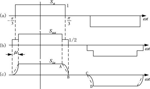
Figure 1. Switching function of six-pulse commutation. (A) ideal commutation; (B) commutation with delay angle; (C) commutation with overlap angle.
The trigger angle control system generally adopts an equally spaced trigger pulse control. The common anode or common cathode valves are turned on sequentially with different phases. The switching function can be expressed by Fourier series. Its general formula is as Equation 3 shows:
When the stacking arc effect of the commutation process is not considered, both the voltage and current have the same form of switching function. As shown in Figure 1A, the switching function has half-wave symmetry, where the An coefficient as Equation 4 shows.
If the overlapping arc effect of the commutation process is considered, that is, there is an overlapping arc angle μ, then the voltage and current have different forms of switching functions. There is a ladder in the voltage switching function. Assuming that the amplitude of the voltage switching function is equal to 1/2 during the commutation period, as shown in Figure 1B, then its coefficient Anu is
During the commutation process, the DC current needs to increase from 0 to a steady-state value or decrease from a steady-state value to 0. The increase/decrease time is determined by the superimposed arc angle μ. Strictly speaking, this process should be a high-slope curve, but for the sake of simplifying calculations, it is linearized, assuming that it increases or decreases in a straight line (as shown by the dotted line in Figure 1B).
The expressions of AB and CD are as follows:
Then, Ani can be written as
When analyzing the modulation effect of the converter on harmonics, in order to simplify the analysis of the main harmonic components, some ideal assumptions are generally made so that conclusions with higher accuracy can be drawn at the same time. These assumptions are as follows:
(1) The three-phase converter transformer is symmetrical, and the parameters of each phase are the same;
(2) The commutation bus voltage does not contain any harmonic components and is three-phase symmetrical;
(3) The trigger angle control system adopts an equal-time interval trigger pulse control.
Therefore, the commutation voltage can be expressed as
The symmetric component method is sued to re-express the three-phase voltage in Equation 8, and then it is substituted into Equation 2. The coefficients are calculated through Equation 5, and the first Fourier decomposition 1 is taken. The voltage component of the AC-side positive sequence voltage transferred to the DC side through the modulation effect of the converter is
Equation 9 shows that when the AC-side positive sequence component is modulated to the DC side, the frequency order is reduced by 1. The negative sequence voltage component of the AC side transmitted to the DC side through the modulation effect of the converter is
Equations 5–10 show that when the AC negative sequence component is modulated to the DC side, the frequency order is reduced by 1. The positive and negative sequence components have the same amplitude, i.e.,
In order to analyze the process in which the converter modulates harmonics from the DC side to the AC side, it is assumed that a small signal is superimposed on the DC current id.
By substituting Equation 11 into the switching function definition Equation 2, the expression of the three-phase current on the AC side can be obtained. After Fourier decomposition and taking the first term, we obtain
Expanding the above formula, we obtain
Equation 13 shows that after the DC side harmonic current is modulated to the AC side through the converter, the frequency of the positive sequence harmonic current on the AC side increases by 1, and the frequency of the negative sequence harmonic current decreases by 1. Both of them have the same amplitude.
2.2 Multi-node harmonic interaction factors
The voltage level in the power system is one of the important factors that determine the power transmission capacity of the DC system. After a system failure, the AC bus voltage of the converter station is most obviously impacted in the DC system. At the same time, voltage stability is the key analysis target after a DC transmission system failure. In order to quantitatively analyze the reactive power and voltage interaction between multiple nodes, the multi-node interaction factor (MNIF) can be used to measure the fundamental voltage interaction between multiple buses/nodes containing commutation buses, which is as Equation 14 shows. The difference between the MNIF and traditional MNIF is that the MNIF is calculated for the rated frequency situation, i.e., 50 Hz, while the MNIF can be suitable for any frequency, especially for the harmonic calculation situations.
This article considers the propagation of harmonics between DC and new energy systems and defines the harmonic interaction factor (harmonic multi-node interaction factor, HMNIF):
In the Equation 15, ΔUni is the change amount of ΔUni in the harmonic voltage value of the bus when the original system is operating under rated conditions and n-order harmonic current is injected into one of its busbars; ΔUnj is the response value of the harmonic voltage change at the primary DC transmission system converter bus to be detected.
In a multi-device feed system, after a disturbance is applied to a certain bus, the dynamic response of the non-perturbed bus will inevitably include the joint effects of the disturbed bus and other buses. Thus,
The larger the HMNIFn,ji value, the greater the impact of the harmonic voltage fluctuation on the bus i on the bus j and vice versa.
When HMNIFn,ji = 0, it can be considered that the two buses operate independently and have no harmonic electrical connection. When HMNIFn,ji = 1, it can be considered that the two buses overlap, and the DC and other equipment are located on the same AC bus.
In power system analysis and calculation, the node equation can be written in the form of the product of the impedance matrix and the current, i.e.,
In the formula,
If the power network node i injects unit nth harmonic current, all other nodes will be open circuit, i.e., the other nodes will be written as Equation 18 below.
Assuming that a three-phase harmonic current source
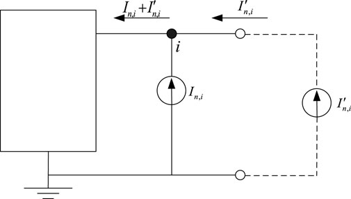
Figure 2. Node equivalent circuit after harmonic injection.
After harmonic injection, the voltage of any node p in the network will change. According to the superposition theorem, the voltage can be expressed by the original matrix elements as
In the formula, In,j represents the injected harmonic current at node j; m is the total number of system nodes; and Zn,pj is the mutual impedance between node p and node j in the harmonic impedance matrix. By simplifying Formula 19, we obtain Equation 20
Considering the nth harmonic voltage increment of the system after harmonic injection, the harmonic current
Substituting Equations 21, 22 into Equation 16, the HMNIF impedance expression can be obtained as follows:
Formula 23 shows that the harmonic interaction factor is related to the self-impedance and mutual impedance of the AC system. That is, when the self-impedance remains unchanged, when the nth three-phase harmonics are input at the bus i current source, the harmonic voltage induced in other buses is related to the electrical distance between the two nodes. The farther the electrical distance is, the greater the mutual impedance is, and the smaller the harmonic interaction factor is.
3 Prevention methods for commutation failure caused by harmonics
3.1 The influence mechanism of harmonics on commutation failure
When a system fault occurs, harmonics are generated due to circuit-breaker opening, increasing DC current, causing converter transformer saturation, abnormal operation of a large number of power electronic components, etc. Currently, the converter bus voltage is no longer a standard sinusoidal quantity. Considering the influence of nth (n ≥ 2) harmonics, the line voltage can be expressed as
In the formula, En is the nth harmonic voltage amplitude and φn is the nth harmonic phase angle, and substituting Equation 24 into Equation 5, we obtain
where
If Equation 26 does not hold, i.e., the time integral of the fundamental voltage and each harmonic voltage on the right side of Equation 25 is not enough to cause the current of thyristor 2 to decrease from Id to 0, at this time, thyristor 2 will continue to conduction, and commutation failure occurs. Thus, Equation 27 can be obtained as below.
where
As shown in Figure 3, the commutation voltage time area required for the commutation process is fixed (determined by Id). Harmonics will cause voltage distortion. This results in an increase in the corresponding commutation time, thereby increasing the commutation overlap angle μ and reducing the extinction angle γ. In severe cases, γ<7o may result in commutation failure.
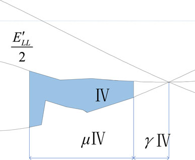
Figure 3. Analysis of the commutation process considering harmonics.
3.2 Prevention method
According to the analysis of the harmonic commutation process in Section 3.1, the important reason for the commutation failure is that the voltage time area is smaller than the DC current, so the commutation cannot be completed within the rated time (commutation margin), and the harmonic voltage will reduce the original area. Some fundamental commutation voltage areas increase the risk of commutation failure. The traditional CDC link avoids commutation failure by limiting the DC current when the DC voltage decreases, without considering the impact of harmonic distortion.
Based on the previous harmonic analysis and the shortcomings of the existing CDC method, this paper adds a commutation failure prevention controller (HCFPCDC) that considers the harmonic distortion after the CDC of the original DC system. As shown in Figure 4, the output of HCFPCDC can reduce the DC current and thereby reduce the voltage time area required for the commutation process.
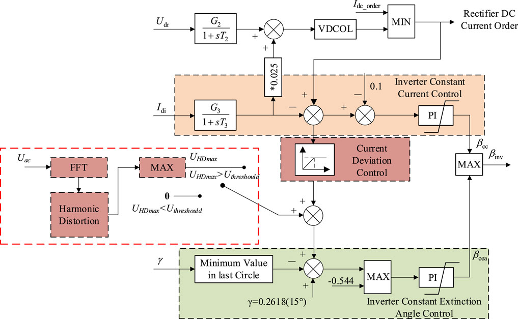
Figure 4. Harmonic commutation failure prevention CDC (HCFPCDC).
As shown in the figure, HCFPCDC monitors the instantaneous value of the AC voltage in real time and performs fast Fourier decomposition (FFT), thereby obtaining the harmonic voltage of each phase in the three-phase voltage. Then, the harmonic voltage distortion rate is calculated according to Equation 28, and then, the highest harmonic voltage distortion rate among the three phases is selected through the MAX module as the feed signal. The module will start the output only when the calculated feed signal exceeds the threshold UHDmax, which can be calculated using Equation 29.
The output of the HCFPCDC can reduce the operating power of the DC system. Therefore, a startup module is set after the maximum output module. This startup module is essentially a selection channel, and its purpose is to prevent the activation of the HCFPCDC when harmonics are few and insufficient to cause commutation failure. This ensures the normal operation of the DC system and reduces unnecessary disturbances.
4 Case study
The system for the case study is a four-generator two-area system, in which the improved CIGRE benchmark HVDC system is integrated, as shown in Figure 5. The parameters of the test system are given in Table 1.
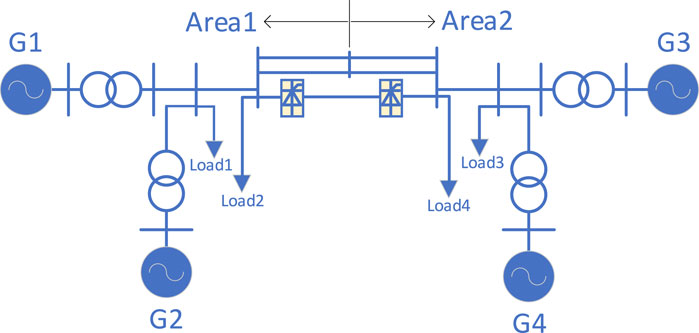
Figure 5. System for the case study.
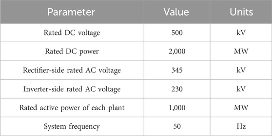
Table 1. Parameters of the case study system.
Based on the above model, a three-phase grounding short-circuit fault is set up at the LCC commutation bus on the inverter side. The fault start time is 3 s, the fault duration is 0.5 s, and the grounding inductance Lf is 0.3 H. The simulation results are given in Figures 6–9, which prove the control effects of proposed methods.
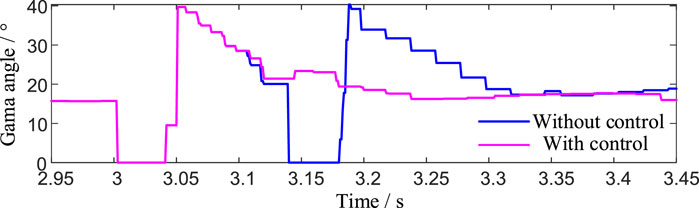
Figure 6. Gamma angle of CLCC during faults.
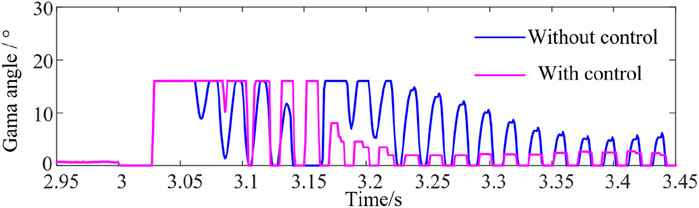
Figure 7. Compensated gamma angle of LCC during faults.
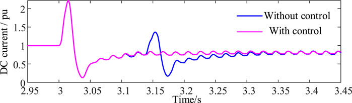
Figure 8. DC current of LCC during faults.
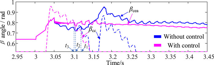
Figure 9. β angle of LCC during faults.
Specifically, as can be seen from simulations, compared with no control, the results with control can effectively suppress the occurrence of subsequent commutation failures and avoid the risk of multiple power shocks to the DC system. After the fault occurs, the arc extinction angle decreases rapidly and reaches 0°. The DC system fails to commutate for the first time. The DC current increases sharply and decreases rapidly after a short period of time. Then, the converter valve recovers, the arc extinction angle jumps significantly, and the DC current under constant current control gradually recovers with the current command of Voltage Dependent Current Order Limiter. In this process, the current deviation control link plays a role. Compared with no control, the control scheme provides the largest compensation arc extinction angle, and in the later stage of recovery, the proposed method can still provide a larger compensation arc extinction angle.
Figure 6 shows that in the early stage of recovery, the arc extinction angle of the system does not increase due to the increase in the compensation arc extinction angle because the DC system is in stage 3 at this time, and the control method is constant current control instead of fixed arc extinction angle control. However, a larger arc extinction angle compensation can make the control mode change time faster, i.e., t3<t2<t1, as shown in Figure 9, ensuring that the system arc extinction angle still maintains a large value after the control mode is changed. After the system enters the fault stable operation state, the compensation extinction angle of the proposed method decreases rapidly. Therefore, the arc extinction angle of the DC system with control is smaller, and LCC transmission with the same active power consumes less reactive power, as shown in Figure 10 and Figure 11. Therefore, the proposed method is more superior to no-control situations and can improve the steady-state operation characteristics of the system under fault conditions.
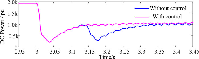
Figure 10. DC active power of the LCC inverter during faults.
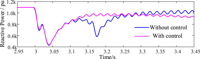
Figure 11. Reactive power of the LCC inverter during faults.
5 Conclusion
In view of the shortcoming that the current research on commutation failure is limited to the fundamental voltage, this paper first analyzes the causes of harmonic generation and its transmission characteristics of AC and DC systems and proposes a quantitative analysis method for the impact of harmonics on commutation failure. On this basis, a corresponding inhibitory control method is proposed. The following conclusions were obtained.
Based on the analysis of the switching function, the nth harmonic generated by the nonlinear change in the DC current during the recovery process after the fault is transmitted to the AC measurement through the converter valve and becomes the n+1-th harmonic. The harmonic coupling characteristics between converter stations in multiple DC systems can be measured by the harmonic interaction factor proposed in this article. The size of the harmonic interaction factor is related to the harmonic self-impedance and harmonic mutual impedance of the node.
Based on the mechanism of the harmonic voltage time area method proposed in this article, a control method (HCFPCDC) to suppress system commutation failure caused by harmonics is proposed. Its parameters and thresholds are determined by the influence coefficients of each harmonic. The CIGRE model and CIGRE-based doubly fed model simulations verify the effectiveness of the controller in suppressing subsequent commutation failures caused by harmonics.
Data availability statement
The original contributions presented in the study are included in the article/Supplementary Material; further inquiries can be directed to the corresponding author.
Author contributions
GZ: writing–original draft and writing–review and editing. JZ: resources and writing–review and editing. YJ: supervision and writing–review and editing. QZ: resources, supervision, and writing–review and editing. KX: resources and writing–review and editing.
Funding
The author(s) declare that financial support was received for the research, authorship, and/or publication of this article. This work was supported by the State Grid Jiangsu Electric Power Co., Ltd., Technology Project under Grant J2023022 (Research on the Impact Mechanism of Large-scale Renewable Energy on Multi-Infeed HVDC System’s Commutation Failure and New Type Commutation Technology).
Conflict of interest
Authors GZ, JZ, YJ, QZ, and KX were employed by State Grid Jiangsu Electric Power Co., Ltd.
The authors declare that this study received funding from State Grid Jiangsu Electric Power Co., Ltd. The funder had the following involvement in the study: data collection and analysis, decision to publish.
Publisher’s note
All claims expressed in this article are solely those of the authors and do not necessarily represent those of their affiliated organizations, or those of the publisher, the editors, and the reviewers. Any product that may be evaluated in this article, or claim that may be made by its manufacturer, is not guaranteed or endorsed by the publisher.
References
ElMehdi, A., Momen, A., and Johnson, B. K. (2014). “Dynamic reactive compensation requirements at the rectifier end of an LCC HVDC link connected to a weak AC system,” in 2014 North American Power Symposium, Pullman WA USA, 07–09 September, 2014.
Jiang, Q., Li, B., Liu, T., Blaabjerg, F., and Wang, P. (2023). Study of cyber attack’s impact on LCC-HVDC system with false data injection[J]. IEEE Trans. Smart Grid, 14, 3220, 3231. doi:10.1109/tsg.2023.3266780
Jiang, Q., Zeng, X., Li, B., Wang, S., Liu, T., Chen, Z., et al. (2022). Time-sharing frequency coordinated control strategy for PMSG-based wind turbine[J]. IEEE J. Emerg. Sel. Top. Circuits Syst., 12(1): 268–278. doi:10.1109/jetcas.2022.3152796
Jingzhe, T. U., Jian, Z., and Jianming, W. (2015). Mechanism analysis on the sending-side instability caused by the receiving-side contingencies of large-scale HVDC asynchronous interconnected power systems. Proc. CSEE 35 (21), 5492–5499.
Krishayya, P. C. S., Adapa, R., Holm, M., and Andersson, G. (1997). IEEE guide for planning DC links terminating at AC locations having low short-circuit capacities. Part I:AC/DC system interaction phenomena. France:CIGRE.
Kristmundsson, G. M., and Carroll, D. P. (1990). The effect of AC system frequency spectrum on commutation failure in HVDC inverters. IEEE Trans. Power Deliv. 2, 1121–1128. doi:10.1109/61.53130
Ouyang, J., Pan, X., Ye, J., Xiao, C., Diao, Y., Zhang, Q., et al. (2023). An improved prediction method of subsequent commutation failure of an LCC-HVDC considering sequential control response[J]. Prot. Control Mod. Power Syst., 8(3): 46–11. doi:10.1186/s41601-023-00323-9
Palone, F., Marzinotto, M., Rebolini, M., Gentili, S., Giannuzzi, G. M., Schembari, M., et al. (2015). “Impact of renewable generation on commutation failures in multiinfeed HVDC systems: a real case study,” in 11th IET International Conference on AC and DC Power Transmission, Birmingham, UK, 10–12 February, 2015.
Peng, Z., and Tianshu, B. I. (2016). Mechanism analysis of large disturbance risk of sub-synchronous oscillation caused by HVDC[J]. Proc. CSEE, 36(4): 961–968.
Shu, H., Wang, S., and Lei, S. (2023). Single-ended protection method for hybrid HVDC transmission line based on transient voltage characteristic frequency band[J]. Prot. Control Mod. Power Syst., 8(2): 26–11. doi:10.1186/s41601-023-00301-1
Song, Y., Luo, Y., and Long, X. (2023). Loss distribution analysis and accurate calculation method for bulk-power MMC[J]. Prot. Control Mod. Power Syst., 8(4): 1–15.
Su, C., Yin, C., Li, F., and Han, L. (2024). A novel recovery strategy to suppress subsequent commutation failure in an LCC-based HVDC[J]. Prot. Control Mod. Power Syst., 9(1): 38–51. doi:10.23919/pcmp.2023.000203
Taherzadeh, E., Radmanesh, H., Javadi, S., and Gharehpetian, G. B. (2023). Circuit breakers in HVDC systems: state-of-the-art review and future trends[J]. Prot. Control Mod. Power Syst., 8(3): 38–16. doi:10.1186/s41601-023-00304-y
Tao, Y., Li, B., Dragičević, T., Liu, T., and Blaabjerg, F. (2020). HVDC grid fault current limiting method through topology optimization based on genetic algorithm[J]. IEEE J. Emerg. Sel. Top. Power Electron., 9(6): 7045–7055. doi:10.1109/jestpe.2020.3026026
Tu, J., Zhang, J., Jia, J., Qin, X., Yi, J., Bu, G., et al. (2017). Study on stability mechanism and influential factors of sending-side three-machine system after multiple HVDC commutation failure[J]. Power Syst. Technol. Press, 41(3): 683–690.
Wang, P. F., Zhang, Y. M., Li, X. Y., and Chen, H. (2012). Interaction analysis of AC/DC systems based on multi-infeed effective short circuit ratio[J]. Power Syst. Prot. Control, 40(6).
Keywords: harmonic impact, HVDC transmission line, commutation failure, suppression method, LCC
Citation: Zhang G, Zhao J, Jia Y, Zhou Q and Xu K (2024) The HVDC commutation failure mechanism impacted by harmonics and its suppression method. Front. Energy Res. 12:1420234. doi: 10.3389/fenrg.2024.1420234
Received: 19 April 2024; Accepted: 26 August 2024;
Published: 16 September 2024.
Edited by:
Ningyi Dai, University of Macau, ChinaReviewed by:
Hong Gong, Energinet, DenmarkKenneth E. Okedu, Melbourne Institute of Technology, Australia
Copyright © 2024 Zhang, Zhao, Jia, Zhou and Xu. This is an open-access article distributed under the terms of the Creative Commons Attribution License (CC BY). The use, distribution or reproduction in other forums is permitted, provided the original author(s) and the copyright owner(s) are credited and that the original publication in this journal is cited, in accordance with accepted academic practice. No use, distribution or reproduction is permitted which does not comply with these terms.
*Correspondence: Guojiang Zhang, emhhbmdndW9qaWFuZ19zZ2NjQDE2My5jb20=