 Qun Li*
 Weijia Tang
- State Grid Jiangsu Electric Power Co., Ltd Research Institute, Nanjing, China
A grid-forming wind generation system exhibits exceptional grid frequency support abilities. The DC capacitor of the grid-forming wind generation system, which is characterized by rapid response and high sensitivity to minor disturbances, can provide short-term inertia support for the power system. This paper proposes the capacitor virtual inertia control for the grid-forming wind generation system, coupling the DC capacitor voltage with the power system frequency, which enables the DC capacitor to participate in the system frequency response process and reduces the rate of change of the system frequency during the disturbance. To analyze the inertia of the wind power generation system, this paper establishes an equivalent Philips–Heffron model for the grid-forming wind generation system and uses the equivalent inertia constant to quantify the inertia of the wind power generation system. The effectiveness of the proposed control strategy and the reasonableness of the inertia assessment method are verified through simulations in the single-turbine system and the IEEE four-machine two-area system.
1 Introduction
To address the escalating energy crisis and environmental pollution, the power industry is undergoing a transformation toward high integration of renewable energies and power converters Xiong et al. (2020). According to the Global Wind Energy Council, global wind power capacity additions in 2023 will be 118 GW, a 36% year-on-year increase. Among renewable energies, full-power wind turbines provide less inertia to the power grid Wu et al. (2017). With the increasing proportion of wind power, the power system frequency security faces a serious challenge. Therefore, the grid codes explicitly require wind farms to have inertial response ability.
Currently, the mainstream types of wind generation are mainly doubly-fed induction generation and permanent-magnet synchronous generator (D-PMSG)-based directly driven wind generation. D-PMSG has better grid compatibility and greater speed range due to the introduction of a full-power converter that completely isolates the generator from the grid. Consequently, it has better wind condition adaptability and is widely used in the power system. The control methods for grid-tied converters of wind generation systems are categorized into grid-following (GFL) control and grid-forming (GFM) control. The GFM control is favored by scholars due to the advantages of not needing phase-locked loop synchronization and being able to provide inertia and damping to the power system Xiong et al. (2019).
In wind generation systems, there are several sources of inertia. The wind turbine rotor, energy storage module, and DC capacitor within the system contribute to the inertia of the wind generation system. Focusing on the GFM control of the wind generation system, scholars have compared various virtual synchronization and inertia control methods and pointed out that the voltage source type control represented by virtual synchronous generator (VSG) control can make the wind generation system have good adaptability in the weak grid Bhende et al. (2011) Yazdi et al. (2019). Zhong et al. (2015) applied the VSG control to the full-power converter in which the rotor-side converter (RSC) is used to achieve DC-side voltage stabilization and the grid-side converter (GSC) is used to achieve maximum wind power tracking, while the disadvantage is that the wind turbine cannot respond to the system frequency. Wang et al. (2015) utilized grid voltage to obtain the voltage reference, directly synthesized the rotor excitation voltage, and provided current limited control using a virtual resistor. Muftau et al. (2020) used constant voltage control for RSC and VSG control for the GSC, which realizes the GFM control of wind generation and maintains DC voltage stabilization, but the disadvantage is that the DC capacitor of the wind generation system cannot provide inertia support for the power system. de Oliveira et al. (2023) used droop control to maintain DC voltage stabilization of the RSC by using torque and power as control objectives. Rodríguez-Amenedo et al. (2021) proposed a control method based on rotor magnetic chain orientation, where the magnetic chain phase angle and amplitude reference are obtained through the torque synchronization link and the voltage droop link, respectively. So it can acquire the rotor excitation voltage control reference, and finally the generator’s internal potential is established to realize GFM control, while the disadvantage of this method is that the fan cannot provide inertia support for the power system. Yazdi et al. (2023) analyzed the coupling relationship between the power angle and rotor speed to elucidate rotor instability characteristics and the influence of control parameters and proposed a D-PMSG GFM frequency-supported control strategy considering rotor stability constraints, which enhanced system frequency stability under various disturbances. Meng et al. (2023) presented a cooperative control scheme for wind farms, along with GFM energy storage devices installed on the AC side. This scheme aims to endow the combined system of renewable energy and energy storage with a voltage source effect, enhancing system damping and inertia. Avazov et al. (2022) proposed an active damping support control strategy. This strategy activates the wind turbine power controller when the DC voltage fluctuation exceeds the designated threshold, subsequently enhancing system damping by using turbine-side resources.
To address the inertial response problem of wind power systems, a GFM control method for D-PMSG-based wind generation system was proposed in Davari and Mohamed (2016). The GSC achieves self-synchronization through DC voltage control, and the RSC employs additional inertia transfer control. However, this method exhibits limited performance in weak grid conditions. Thakallapelli et al. (2019) achieved inertial synchronization control by controlling the DC voltage of the GSC, enabling the wind turbine system to behave as a virtual voltage source for the power grid. Lai et al. (2017) demonstrated the potential of integrating flywheel energy storage on the DC side of the D-PMSG, where the DC bus voltage control of the flywheel aids in realizing virtual synchronous control for the GSC during grid connection. This not only enhances the system inertia response but also ensures DC bus voltage stability. Sang et al. (2021) configured flywheel energy storage on the DC side of the D-PMSG in which the flywheel energy storage adopts DC bus voltage control during grid-tied operation, the GSC realizes virtual synchronous control, and finally it realizes the purposes of improving the system inertia response ability, smoothing the active power of the wind generation system, and maintaining DC voltage stability. Pazmiño et al. (2021) proposed a novel approach to energy storage GFM frequency active support control. This approach combines constant frequency control with frequency modulation state transfer control, thereby departing from traditional control methods such as virtual inertia and primary frequency modulation. He et al. (2024) developed a system frequency response model incorporating a wind turbine with integrated inertia control. The study derives an analytical equation for the effective inertia time constant in the wind turbine frequency modulation process and assesses its inertia support capacity.
In this paper, a GFM control method for the D-PMSG-based wind generation system is proposed, where the DC capacitor voltage is coupled with the system frequency, enabling the DC capacitor to participate in the system frequency response process. The remainder of this manuscript is structured as follows: Section 2 introduces the basic GFM control strategy of the D-PMSG-based wind generation system. Section 3 introduces the proposed capacitor virtual inertia control. Section 4 presents the equivalent Philips–Heffron model of the wind power system and analyzes the equivalent inertia of the system. Finally, Section 5 verifies the sophistication and effectiveness of the proposed control method.
2 GFM control strategy for the D-PMSG-based wind generation system
The specific structure of the D-PMSG-based wind generation system is shown in Figure 1, which consists of the wind turbine, D-PMSG, and back-to-back converter. The RSC maintains DC capacitor voltage stabilization, and the GSC controls the magnitude and frequency of the voltage tied to the grid.

Figure 1. Structure of the D-PMSG-based wind generation system.
2.1 Modeling of the wind turbine
The mechanical power of a D-PMSG-based wind generation system Liu et al. (2016) can be expressed as
where Pwm is the mechanical power of the wind turbine; ρ is the air density; Rw is the blade radius of the wind turbine; λ is the tip speed radio of the wind turbine; Cp is the wind energy utilization factor; β is the pitch angle of the wind turbine; ωw is the angular velocity of the wind turbine; vw is the inlet wind speed.
In (1), it is clear that Pwm is influenced by Cp, and Cp is the function of λ and β. When β increases, Cp decreases. At the same time, there exists a unique λ that maximizes Cp when β is the same, and when Rw and vw are constant values, λ is in direct proportion to ωw. So, for each vw, there is a ωw corresponding to the maximum Pwm. Therefore, to obtain the maximum power and wind energy utilization factor, the rotational speed of the wind turbine must be adjusted according to the wind speed correspondingly.
2.2 RSC control strategy
For the conventional GFM wind generation system, the GSC adopts a constant capacitor voltage control to ensure the stability of the DC capacitor voltage Udc, as shown in Figure 2.
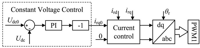
Figure 2. Constant voltage control strategy of the RSC.
The generator stator phase voltage can be expressed as
where ωs is the rotor angular frequency; Lsq is the stator q-axis inductance; isq is the stator current q-axis component; φf is the stator magnetic chain.
The electromagnetic torque and active power of D-PMSG are only related to isq. Therefore, adjusting isd does not affect the active power output of the wind turbine. In vector control, the d-axis current isd usually has the value of 0, to hence using all of the current to generate electromagnetic torque.
2.3 GSC control strategy
The GSC adopts virtual synchronous generator (VSG) control that can support the frequency and magnitude of the grid voltage Xiong et al. (2015), as shown in Figure 3.
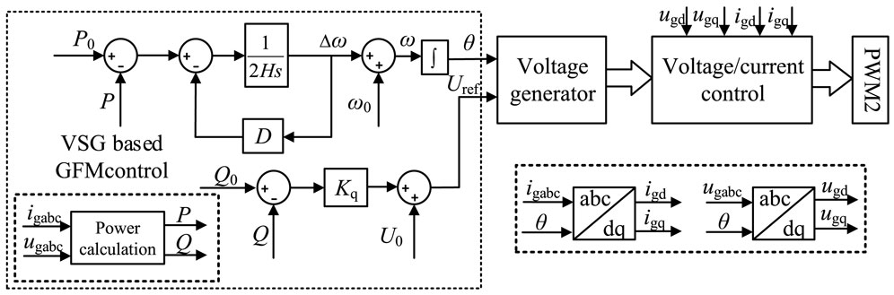
Figure 3. GSC control strategy.
The VSG control is composed of two primary components: P-f control and Q-U control. The former introduces the concept of virtual inertia in the GSC by simulating the rotor motion equations of the synchronous machine. The P-f control equation for the VSG control of the GSC is
where H is the inertia time constant; D is virtual damping; ω is the grid angular velocity; ω0 is the grid rated angular velocity; P is the grid-side output power; P0 is the power command value.
The Q-U control obtains the command value of the output voltage magnitude by simulating the reactive power droop characteristic of the synchronous machine. The Q-U control equation for VSG control of the GSC is
where Uref is the commanded value of the grid-side voltage; U0 is the rated value of the grid-side voltage; Kq is the Q-U control coefficient; Q is the grid-side reactive power; Q0 is the reference value of reactive power.
The GSC adopts VSG control to realize the wind generation system externally, being the voltage source characteristics, and effectively support the grid-side voltage and frequency.
3 Capacitor virtual inertia control
3.1 Control strategy
The GSC of the conventional GFM control for D-PMSG utilizes constant capacitor voltage control, where the entirety of inertia support is sourced from the wind turbine rotor. To enable the DC capacitor to contribute to the frequency response, this manuscript proposes a novel capacitor virtual inertia (CVI) control, illustrated in Figure 4.
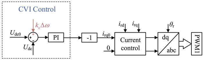
Figure 4. CVI control.
This control strategy adds an auxiliary voltage regulation command to the constant voltage control loop, changing the reference voltage from Udc0 to Udcref, i.e.,
where kc is the regulation coefficient; Δω is the angular frequency deviation; Udc0 is the initial value of the capacitor voltage; ΔU is the capacitor voltage deviation.
The CVI control couples the DC capacitor voltage to the grid frequency deviation. When the grid is disturbed, the proposed control can make the DC capacitor provide the inertia support, thus reducing the rate of change of frequency.
3.2 Capacitor equivalent inertia analysis
Normally, constant capacitor voltage control is implemented to keep the DC capacitor voltage stable, but it does not integrate the capacitor into the frequency response. As a result, under constant voltage control, the equivalent inertia provided by the capacitor is negligible. However, with the introduction of CVI control in the RSC, the interplay between capacitor voltage and grid frequency allows the capacitor to contribute to inertia support, thereby enhancing equivalent inertia. The analysis process is detailed below.
During steady-state operation, the energy stored by the capacitor is
where Cdc is the DC capacitor value and Udc is the DC capacitor voltage.
When the DC capacitor responds to the frequency deviation, the electric energy deviation of the capacitor is given by
where
The value of the equivalent capacitor is
Define the equivalent adjustment coefficient
The relationship between
Under CVI control, the equivalent inertia time constant of the capacitor is
where SB is the rated capacity of the wind turbine and
Eq 11 reveals that under CVI control, the dynamic regulation range of the DC capacitor is significantly broader and its inertia characteristics not only depend on its value but also on the regulation coefficient kc and the steady-state operating point. To exemplify, Figure 5 depicts the interdependence between the capacitor equivalent inertia time constant Hc, DC capacitor Cdc, regulation coefficient kc, and the steady-state operating point Udc0 in a grid rated at 300 kW.
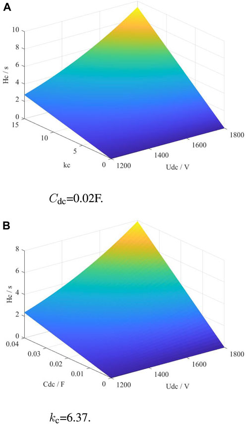
Figure 5. Analysis of factors affecting capacitor equivalent inertia. (A) Cdc = 0.02F. (B) kc = 6.37.
Figure 5 illustrates that under CVI control, the equivalent inertia provided by the capacitor is related to multiple parameters, and the equivalent inertia can be greater than its inherent inertia. The proposed control enables the capacitor to provide the energy required for the frequency response of the grid.
4 Wind power system equivalent inertia analysis
4.1 Philips–Heffron model of the power system with GFM wind generation
In the preceding section, this manuscript proposed a GFM control strategy for the wind generation system that employs CVI control for RSC and VSG control for the GSC. To investigate the equivalent inertia of the entire power system with the wind generation controlled by the proposed GFM strategy, an equivalent Philips–Heffron model is developed, as illustrated in Figure 6.
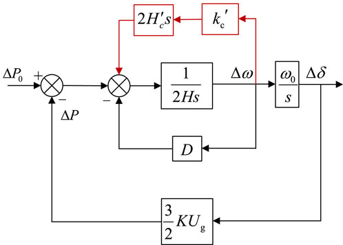
Figure 6. Equivalent Philips–Heffron model.
Under the CVI control, the mathematical expression of the equivalent Philips–Heffron model of the entire power system with wind generation controlled by the proposed GFM strategy is as follows:
According to (12), TJ is the equivalent inertial time constant, increasing TJ can reduce the frequency rate of system during disturbances. TD is the equivalent damping time constant, increasing TD reduces the frequency deviation of the system during disturbances. TS is the equivalent synchronization time constant, reflecting the self-synchronization capability of the GFM D-PMSG.
where Us is the converter side voltage, Ug is the grid-side voltage, X is the system impedance, and δ0 is the rated power angle.
According to (13), TJ is intricately linked to both the VSG control equivalent inertia time constant H and the capacitor equivalent inertia time constant Hc, wherein H depends on the VSG control parameter in the GSC and its energy support source is the rotor; Hc is determined by the proposed CVI control parameter, and its energy source is the DC capacitor. TD depends on the virtual damping parameter D in the VSG control. TS depends on the electrical parameters of the converter and the grid.
4.2 Analysis of factors affecting the equivalent inertia of D-PMSG
According to the equivalent Philips–Heffron model of the entire power system with the wind generation controlled by the proposed GFM strategy, the composite equivalent inertia is composed of two distinct components. In the subsequent analysis, we will delve into the individual influencing factors of Hc and H.
4.2.1 Equivalent capacitor inertia time constant
According to 11, the equivalent inertia time constant Hc under virtual inertia regulation is related to the regulation coefficient kc, the DC capacitor capacity Cdc, the initial DC capacitor voltage Udc0, and the rated capacity of the wind turbine SB.
1. The larger the adjustment coefficient kc is, the larger the equivalent inertial time constant is. It can be seen from 5 that with the increase of kc, the voltage deviation ΔUdc of the DC capacitor also increases gradually. Since the converter is limited by voltage, the DC capacitor voltage should be greater than 1.23 Ug. Consequently, excessive voltage deviation is prohibited, constraining the viable range for selecting the adjustment coefficient kc.
2. An increase in Cdc leads to a larger Hc, but practical considerations limit the choice: a larger capacitor implies larger and more expensive components. Although the supercapacitors’ value can reach the farad level, the economy is poor in engineering application. Moreover, the larger the capacitor value, the lower the capacitor voltage, and the reduction in voltage leads to a reduction in the equivalent inertia time constant.
3. Higher Udc0 contributes to a larger Hc. However, in operational scenarios, it is crucial to maintain a reasonable initial voltage to prevent converter overvoltage, which can disrupt normal functioning and cause economic losses.
4. A smaller SB value increases the Hc. However, in the case of the selected wind turbine, the rated capacity SB is a fixed value.
4.2.2 Equivalent inertial time constant of VSG control
The VSG control mechanism facilitates the converter’s participation in the frequency response by emulating synchronous machine dynamics. Its equivalent inertia constant, H, can be adjusted by changing the control parameters. However, it is important to note that the inertia support power derived from the rotors of the wind turbine comes at the expense of rotor speed during disturbances. Consequently, the inertia parameters of VSG control need to be reasonably set according to the actual situation and can not only consider the need to increase the gird inertia, while ignoring the frequency response costs.
5 Verification
5.1 Single-turbine grid-connected system
To verify the effectiveness of the proposed CVI control and the correctness of the equivalent Philips–Heffron model, a simulation model of the single D-PMSG wind generation system, as shown in Figure 1, is constructed in MATLAB/Simulink. The main parameters of the simulation model are given in Table 1.
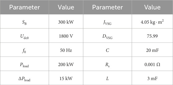
Table 1. Simulation parameters.
The simulation model is built according to the control strategy described in Sections 2, 3, with CVI control for the RSC and VSG control for the GSC. Under the initial conditions, the local load at the grid side is 200 kW, and the 15 kW additional disturbance is introduced at 10 s. The system frequency waveforms and DC capacitor voltage waveforms of CVI control and constant voltage control are compared, as shown in Figure 7.
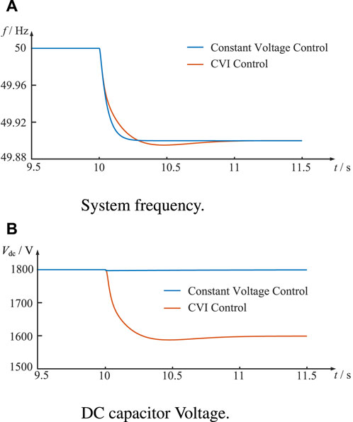
Figure 7. Waveform comparison of constant voltage and CVI control in single-turbine system. (A) System frequency. (B) DC capacitor voltage.
The system frequency waveforms under CVI control and constant voltage control are depicted in Figure 7A. The rate of change of the system frequency is smaller under CVI control, indicating that the proposed control increases the equivalent inertia. The steady-state frequency under both controls remains at 49.9 Hz. This consistency arises because the system inertia affects only the transient characteristics of the frequency without influencing its steady-state behavior. Additionally, the system frequency waveform under CVI control is lower than that under constant voltage control from 10.2 s to 11.2 s, corresponding to the overshooting of the DC capacitor voltage under CVI control. This occurs because the DC capacitor undergoes a discharging process to provide inertial support power to the system during the initial stage of the disturbance, necessitating a subsequent charging process.
Figure 7B illustrates the DC capacitor voltage waveforms under both control strategies. When a load disturbance occurs, the DC capacitor voltage under constant voltage control has only a small fluctuation and recovers to 1800 V quickly. In contrast, the DC capacitor voltage under CVI control drops from 1800 V to 1600 V and subsequently keeps stabilizing due to the coupling between the DC capacitor voltage and the system frequency deviation. This dynamic behavior under CVI control has provided inertia support for the power system and enhanced the equivalent inertia of the power system.
To verify the specific impact of CVI control on frequency dynamics, the system frequency and DC capacitor voltage waveforms are conducted under the same operating condition at different regulation coefficients kc. The results are shown in Figure 8.
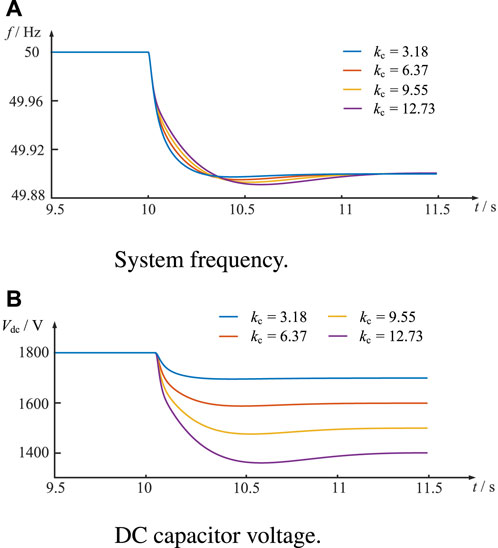
Figure 8. Waveform comparison of constant voltage and CVI control under different kc. (A) System frequency. (B) DC capacitor voltage.
Figure 8A shows that the rate of change of the frequency decreases with the increase of the regulation coefficient kc, indicating that the stronger the coupling between the regulated DC capacitor voltage and the frequency deviation of the system, the larger the equivalent inertia provided by the CVI control to the system. In addition, the overshooting of the frequency waveform between 10.2 s and 11.2 s also increases with the increase in the regulation coefficient kc because the overshooting of the DC capacitor voltage drop process becomes larger with the increase in the regulation coefficient kc, and more energy is required in the charging process before it reaches the steady state. The DC capacitor voltage waveforms under different regulation coefficients kc are shown in Figure 8B, and it reveals that the larger the regulation coefficient kc is, the more inertia-supporting power is provided by the DC capacitor, corresponding to a larger voltage drop.
5.2 Multi-machine system
The IEEE four-machine two-area (4M2A) system is a commonly used theoretical model in the power system to study the power transmission and control between neighboring regions in a power system. To further verify the correctness and effectiveness of the control method proposed in this paper, an IEEE 4M2A simulation model with a wind generation system is constructed, as shown in Figure 9.
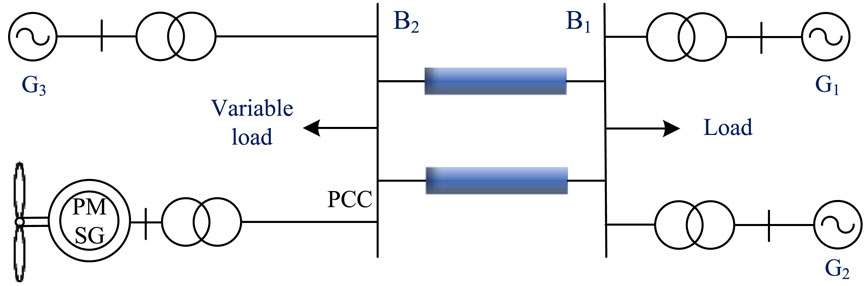
Figure 9. 4M2A system with the wind generation system.
Area 1 consists of two synchronous generators SG1 and SG2 and stational load, whereas area 2 consists of synchronous generator SG3, D-PMSG single-turbine system replacing synchronous machine SG4, and variable load where PCC is the wind generator merging point. Initially, the load demand is 225 MW, with a variable load of 119.5 MW. At 40 s, a sudden disturbance of 50 MW is imposed on the variable load. The comparative analysis of system frequency and DC capacitor voltage waveforms under CVI and fixed-voltage control conditions is shown in Figure 10.
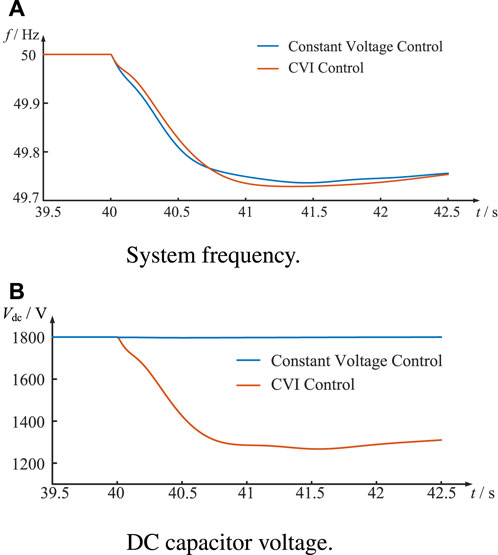
Figure 10. Waveform comparison of constant voltage and CVI control in multi-machine system. (A) System frequency. (B) DC capacitor voltage.
Figure 10A shows that in the multi-machine power system, the rate of change of system frequency is smaller under CVI control, indicating that this control increases the equivalent inertia of the wind power system. However, due to the relatively slow frequency response process of the synchronizer in the system, there is a small recovery when the system frequency drops to its lowest point. The DC capacitor voltage waveform is shown in Figure 10B, where the capacitor voltage remains stable under constant voltage control, while the DC capacitor voltage drops to about 1300 V under CVI control to provide inertia support to the power system.
In summary, analysis of simulation results for both the single-turbine and 4M2A systems under CVI control demonstrates its superiority over constant voltage control. CVI control facilitates the DC capacitor responsiveness to system frequency changes, effectively delaying system frequency decrease. This response aligns with the demands of the frequency response, providing the system with a reasonable level of inertia support.
6 Conclusion
This paper proposes a CVI control strategy for the GFM wind generation system and employs the Philips–Heffron model to analyze the equivalent inertia of the entire power system with the wind generation controlled by the proposed GFM strategy. The corresponding single-turbine test system and 4M2A test system are constructed to carry out the simulation validation. The main conclusions are as follows:
1. The CVI control effectively couples the DC capacitor voltage to the grid frequency deviation. When the power grid is disturbed, the CVI control can make the DC capacitor participate in the frequency response, provide the inertia support for the power grid, and reduce the rate of change of frequency.
2. The equivalent Philips–Heffron model was established to analyze the equivalent inertia of the entire power system with the wind generation controlled by the proposed GFM strategy.
3. The single-turbine and 4M2A test system models are constructed to verify the effectiveness of the proposed GFM control strategy and the correctness of the inertia analysis results.
Data availability statement
The original contributions presented in the study are included in the article/Supplementary Material; further inquiries can be directed to the corresponding authors.
Author contributions
QuL: conceptualization, data curation, formal analysis, investigation, methodology, software, writing–original draft, and writing–review and editing. QiL: conceptualization, data curation, software, supervision, and writing–original draft. WT: validation, visualization, and writing–review and editing. CW: project administration, resources, and writing–review and editing.
Funding
The author(s) declare that financial support was received for the research, authorship, and/or publication of this article. This work was supported by the Science And Technology Project of State Grid Jiangsu Electric Power Co., Ltd (J2023021).
Acknowledgments
The authors wish to thank the project funding from the Science And Technology Project of State Grid Jiangsu Electric Power Co., Ltd (J2023021).
Conflict of interest
Authors QuL, QiL, WT, and CW were employed by State Grid Jiangsu Electric Power Co., Ltd. Research Institute.
The authors declare that this study received funding from State Grid Jiangsu Electric Power Co., Ltd. The funder had the following involvement in the study: the study design, collection, analysis, interpretation of data, and the writing of this article.
Publisher’s note
All claims expressed in this article are solely those of the authors and do not necessarily represent those of their affiliated organizations, or those of the publisher, the editors, and the reviewers. Any product that may be evaluated in this article, or claim that may be made by its manufacturer, is not guaranteed or endorsed by the publisher.
References
Avazov, A., Colas, F., Beerten, J., and Guillaud, X. (2022). Application of input shaping method to vibrations damping in a type-iv wind turbine interfaced with a grid-forming converter. Electr. Power Syst. Res. 210, 108083. doi:10.1016/j.epsr.2022.108083
Bhende, C., Mishra, S., and Malla, S. G. (2011). Permanent magnet synchronous generator-based standalone wind energy supply system. IEEE Trans. Sustain. energy 2, 361–373. doi:10.1109/tste.2011.2159253
Davari, M., and Mohamed, Y. A.-R. I. (2016). Robust dc-link voltage control of a full-scale pmsg wind turbine for effective integration in dc grids. IEEE Trans. Power Electron. 32, 4021–4035. doi:10.1109/tpel.2016.2586119
de Oliveira, J. D. A., de Araújo Lima, F. K., Tofoli, F. L., and Branco, C. G. C. (2023). Synchronverter-based frequency control technique applied in wind energy conversion systems based on the doubly-fed induction generator. Electr. Power Syst. Res. 214, 108820. doi:10.1016/j.epsr.2022.108820
He, H., Xiao, H., and Yang, P. (2024). Analysis and quantitative evaluation of wind turbine frequency support capabilities in power systems. Front. Energy Res. 12, 1363198. doi:10.3389/fenrg.2024.1363198
Lai, J., Song, Y., and Du, X. (2017). Hierarchical coordinated control of flywheel energy storage matrix systems for wind farms. IEEE/ASME Trans. Mechatronics 23, 48–56. doi:10.1109/tmech.2017.2654067
Liu, J., Wen, J., Yao, W., and Long, Y. (2016). Solution to short-term frequency response of wind farms by using energy storage systems. IET Renew. Power Gener. 10, 669–678. doi:10.1049/iet-rpg.2015.0164
Meng, J., Wang, D., Wang, Y., Guo, F., and Yu, J. (2023). An improved damping adaptive grid-forming control for black start of permanent magnet synchronous generator wind turbines supported with battery energy storage system. IET Generation, Transm. Distribution 17, 354–366. doi:10.1049/gtd2.12753
Muftau, B., Fazeli, M., and Egwebe, A. (2020). Stability analysis of a pmsg based virtual synchronous machine. Electr. Power Syst. Res. 180, 106170. doi:10.1016/j.epsr.2019.106170
Pazmiño, I., Martinez, S., and Ochoa, D. (2021). Analysis of control strategies based on virtual inertia for the improvement of frequency stability in an islanded grid with wind generators and battery energy storage systems. Energies 14, 698. doi:10.3390/en14030698
Rodríguez-Amenedo, J. L., Gómez, S. A., Martínez, J. C., and Alonso-Martinez, J. (2021). Black-start capability of dfig wind turbines through a grid-forming control based on the rotor flux orientation. IEEE Access 9, 142910–142924. doi:10.1109/access.2021.3120478
Sang, S., Pei, B., Huang, J., Zhang, L., and Xue, X. (2021). Low-voltage ride-through of the novel voltage source-controlled pmsg-based wind turbine based on switching the virtual resistor. Appl. Sci. 11, 6204. doi:10.3390/app11136204
Thakallapelli, A., Kamalasadan, S., Muttaqi, K. M., and Hagh, M. T. (2019). A synchronization control technique for soft connection of doubly fed induction generator based wind turbines to the power grids. IEEE Trans. Industry Appl. 55, 5277–5288. doi:10.1109/tia.2019.2917654
Wang, S., Hu, J., and Yuan, X. (2015). Virtual synchronous control for grid-connected dfig-based wind turbines. IEEE J. Emerg. Sel. Top. power Electron. 3, 932–944. doi:10.1109/jestpe.2015.2418200
Wu, Z., Gao, D. W., Zhang, H., Yan, S., and Wang, X. (2017). Coordinated control strategy of battery energy storage system and pmsg-wtg to enhance system frequency regulation capability. IEEE Trans. Sustain. Energy 8, 1330–1343. doi:10.1109/tste.2017.2679716
Xiong, L., Liu, X., Zhang, D., and Liu, Y. (2020). Rapid power compensation-based frequency response strategy for low-inertia power systems. IEEE J. Emerg. Sel. Top. Power Electron. 9, 4500–4513. doi:10.1109/jestpe.2020.3032063
Xiong, L., Liu, X., Zhao, C., and Zhuo, F. (2019). A fast and robust real-time detection algorithm of decaying dc transient and harmonic components in three-phase systems. IEEE Trans. Power Electron. 35, 3332–3336. doi:10.1109/tpel.2019.2940891
Xiong, L., Zhuo, F., Wang, F., Liu, X., Chen, Y., Zhu, M., et al. (2015). Static synchronous generator model: a new perspective to investigate dynamic characteristics and stability issues of grid-tied pwm inverter. IEEE Trans. Power Electron. 31, 6264–6280. doi:10.1109/tpel.2015.2498933
Yazdi, S. S. H., Milimonfared, J., Fathi, S. H., Rouzbehi, K., and Rakhshani, E. (2019). Analytical modeling and inertia estimation of vsg-controlled type 4 wtgs: power system frequency response investigation. Int. J. Electr. Power and Energy Syst. 107, 446–461. doi:10.1016/j.ijepes.2018.11.025
Yazdi, S. S. H., Shokri-Kalandaragh, Y., and Bagheri, M. (2023). Power system stability improvement considering drive train oscillations of virtual synchronous generator-regulated type-4 wind turbines. IET Renew. Power Gener. 17, 579–603. doi:10.1049/rpg2.12616
Keywords: wind generation system, grid-forming control, capacitor virtual inertia control, system frequency response, Philips–Heffron model, equivalent inertia
Citation: Li Q, Li Q, Tang W and Wang C (2024) Capacitor virtual inertia control and equivalent inertia analysis for a grid-forming wind generation system. Front. Energy Res. 12:1418229. doi: 10.3389/fenrg.2024.1418229
Received: 16 April 2024; Accepted: 22 May 2024;
Published: 18 June 2024.
Edited by:
Liansong Xiong, Xi’an Jiaotong University, ChinaReviewed by:
Xiaokang Liu, Polytechnic University of Milan, ItalyXin Li, Southeast University, China
Copyright © 2024 Li, Li, Tang and Wang. This is an open-access article distributed under the terms of the Creative Commons Attribution License (CC BY). The use, distribution or reproduction in other forums is permitted, provided the original author(s) and the copyright owner(s) are credited and that the original publication in this journal is cited, in accordance with accepted academic practice. No use, distribution or reproduction is permitted which does not comply with these terms.
*Correspondence: Qun Li, cXVuX2xpQHNpbmEuY29t; Weijia Tang, dGFuZ19qc2VwY0AxMjYuY29t