 Lin Cheng1*
 Dongping Ai
95% of researchers rate our articles as excellent or good
Learn more about the work of our research integrity team to safeguard the quality of each article we publish.
Find out more
ORIGINAL RESEARCH article
Front. Energy Res. , 03 July 2024
Sec. Wind Energy
Volume 12 - 2024 | https://doi.org/10.3389/fenrg.2024.1417360
This paper presents the dynamic voltage stability index based on the voltage oscillation loop for power systems integrated with multiple permanent magnet synchronous generators (PMSGs) to assess the dynamic interaction on voltage stability. First, the model of power systems integrated with multi-PMSGs using a Q–V sensitivity matrix as feedback to connect all PMSGs is established. The transfer function model between voltage and reactive power is derived, and the voltage oscillation loop can be derived, which exists in each PMSG. Next, the dynamic voltage stability index is theoretically derived and given, the impact of dynamic interaction among multi-PMSGs on voltage stability can be quantified, and the source of voltage oscillation can be identified and determined. Then, the voltage stability is recovered by shedding the trouble-making PMSG. The parameters of PMSGs could be tuned with the guidance of the dynamic voltage stability index to reduce the risk of voltage oscillation. Finally, the example of a test system with PMSGs is used to validate the correctness of the dynamic stability index.
Wind power has been applied extensively in many nations as a rich and clean renewable energy source (Kroposki et al., 2017; Wang X. et al., 2015). Among all kinds of wind turbine generators (WTGs), permanent magnet synchronous generators (PMSGs) can be widely used because of its high efficiency and reliability (Li et al., 2012; Sanchez et al., 2012). However, the risk of power angle instability, voltage instability, and frequency instability might increase when power electronic converters are used to link massive amounts of wind generators to the power system. At home and abroad, accidents caused by grid-connected WTGs have been reported recently (Wang L. et al., 2015; Adams et al., 2012), such as the wind farm located in Hebei Province of North China (Wang L. et al., 2015), the Harmi area of West China (Liu et al., 2017), and Texas of the USA (Adams et al., 2012), subsequently causing the tripping of a great number of WTGs and damage to crowbar circuits. These accidents have brought serious challenges to power angle stability, voltage stability, and frequency stability (Rakhshani et al., 2019), which are coupled with each other during the disturbances. In order to improve the stability of renewable energy grid-connected systems, scholars have conducted extensive research. Belkhier and Oubelaid (2024) provided a solution to address the intermittent and stochastic nature of renewable energy management and improve the efficiency of energy systems. A novel control approach is proposed by Khosravi et al. (2023) to improve the stability of hybrid AC/DC microgrids. Dashtdar et al. (2022) provided a new protection method for DC microgrids based on the Fourier transform. Wijnhoven et al. (2014) discussed a selection of control aspects that are important for the negative sequence current injection of type 4 wind turbines. A new WT and VSC-HVDC control method is proposed by Erlich (2017), which can determine the reference voltage directly.
Meanwhile, voltage stability is gaining more attention due to the high penetration of wind generation, and scholars have studied some strategies to improve voltage stability (Ou et al., 2016; Liu and Sun, 2014). Ou et al. (2016); Sravan Kumar et al. (2014) improved voltage stability through the coordination of reactive power. The method of coordinated dynamic VAR source placement is applied for voltage stability enhancement by Liu et al. (2018); Chi and Xu (2020). The voltage stability and control of offshore wind farms with AC collection and HVDC transmission are investigated through impedance models by Liu and Sun (2014). Voltage stability is more complex with the dynamic interaction among the dynamic units, such as synchronous and wind generators (Qian et al., 2016). Hence, proposing the voltage stability index to evaluate dynamic interaction quantitatively is necessary.
Numerous researchers have developed techniques for assessing the voltage stability of power systems with wind generators, including the continuous power flow method, probability analysis method, and bifurcation theory method. Vittal et al. (2010) provided a detailed methodology to assess the influence of wind turbine generators on the static voltage stability of the power system by combining economic dispatch, power flow, unit dedication, and past time-series information. Rawat and Vadhera (2020) proposed a method to analyze the stable state probabilistic voltage stability margins considering generation and load demand uncertainty. The model is presented to analyze the static voltage stability of the system integrated with WTGs based on bifurcation theory by Tourandaz Kenari et al. (2019), and the probabilistic index can be used to examine the probability risk of voltage collapse.
However, the methods proposed above focus on steady voltage stability. With the dynamic time scale of the power system becoming shorter due to the significant penetration of wind power, the dynamic characteristics of voltage stability cannot be neglected. The scholars have conducted meaningful research studies on the dynamic voltage stability of the power system integrated with WTGs. Venkatesh et al. (2007) presented a dynamic voltage collapse index programmed into a microprocessor-based relay to reflect the risk of voltage collapse over the feeder connecting WTGs. Baa Wafaa and Dessaint (2018) proposed an improved voltage stability index to assess the stability of the system with WTG integration by considering optimal power flow. Su et al. (2019) focused on the dynamic interaction between WTGs and induction motor loads and examined the dynamic voltage stability process from the modal coupling aspect.
As the quantity of WTG grows, the influence of dynamic interactions between multiple wind turbine generators on voltage stability is becoming more dominant. However, the dynamic interactions that exist in multiple wind turbine generators are rarely considered in terms of voltage stability, especially when quantifying the influence of each remaining wind generator on the voltage stability of a selected wind generator in a system with multiple wind turbine generators. Therefore, the paper presents the dynamic voltage stability index for a system integrated with multi-PMSGs based on the voltage oscillation loop, and the index proposed can quantify the influence of dynamic interaction among multi-PMSGs on voltage stability.
The proposed method is more suitable for the analysis of dynamic voltage stability than the continuous power flow method (Vittal et al., 2010), probability analysis method (Rawat and Vadhera, 2020), and bifurcation theory method (Tourandaz Kenari et al., 2019), rather than being limited to analyzing steady voltage stability. Compared with the methods proposed by Venkatesh et al. (2007); Baa Wafaa and Dessaint (2018), this method can be used to analyze the impact of dynamic interaction on dynamic voltage stability. Su et al. (2019) analyzed the dynamic interaction between WTGs and induction motor loads but did not quantitatively analyze the dynamic interaction among each WTG. Harmonic modeling of the wind turbine induction generator is presented by García et al. (2018), and the method analyzes the harmonic interaction between the wind power generator and the power system, but it is difficult to analyze the dynamic interaction among wind power generators considering the voltage characteristics. Therefore, the proposed method has improved the shortcomings of the methods proposed by Su et al. (2019); García et al. (2018).
In Section 2, the interconnected model of the power system integrated with multi-PMSGs is proposed, and the voltage oscillation loops that exist between PMSGs are derived. In Section 3, the dynamic voltage stability index based on the voltage oscillation loop is introduced, and the theoretical derivation and calculation steps of the index are presented. Based on the voltage stability index, the source of voltage oscillation can be identified and the parameter tuning of PMSGs can be guided. In Section 4, the validity of the proposed dynamic voltage stability index is tested under different scenarios in the test system. Section 5 summarizes the novelty and main contributions. The novelty and contributions of the paper are mainly reflected in four aspects: 1) the transfer function model between voltage and reactive power at the point of common coupling is derived by combining the dynamic equation of PMSGs and the power equation at the point of common coupling; then the voltage oscillation loop of PMSG is derived. 2) The dynamic model of power systems integrated with multi-PMSGs using the Q–V sensitivity matrix as feedback to connect all PMSGs is established. 3) The dynamic voltage stability index is theoretically derived and given, the impact of dynamic interaction among multi-PMSGs on voltage stability can be quantified, the source of voltage oscillation can be identified and determined, and then the voltage stability is recovered by shedding the trouble-making PMSG. 4) The parameters of PMSGs could be tuned with the guidance of the dynamic voltage stability index to reduce the risk of voltage oscillation.
The configuration of the power system integrated with multi-PMSGs is shown in Figure 1, and PMSGs are connected to N nodes.
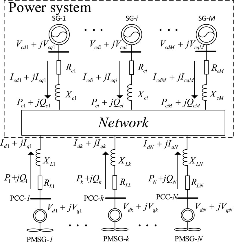
Figure 1. Power system with multi-PMSGs.
An interconnected model of the transfer function of the whole system is established to analyze the voltage stability of power system integrated with multi-PMSGs.
Figure 1 depicts the precise structure of the power system. There are M SGs and N points of common coupling (PCC) of PMSGs. Denote
where
From Eq. 1, the model of SG-i can be obtained as
where
By combining Eqs 1, 2, there is a clear expression for the SG-i model. Therefore, the model of the whole system is derived by combining PMSGs and SGs.
Figure 2 depicts the PMSG-k structure coupled to the power system.
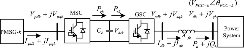
Figure 2. PMSG-k connected to the power system.
Consider the PCC-k (
where subscripts d and q stand for d- and q-axis components in the d–q coordinate, respectively.
The model of PMSG-k can be determined as follows (Li et al., 2012; Du et al., 2017):
where
From Figure 2, the equations of active and reactive power outputs of PMSG-k are obtained as follows:
where the variable at the steady state is denoted by subscript 0.
In this way, the currents of PMSG-k can be obtained as
where
By combining Eqs 3–6, the linearized line current equations could be written as Eq. 7.
Figure 3 shows the configuration of the MSC vector control of PMSG-k, and there are three control loops in Figure 3: part 1 is speed control, part 2 is q-axis current control, and part 3 is d-axis current control.
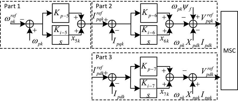
Figure 3. MSC vector control of PMSG-k.
From Figure 3, the model of the three loops of the MSC vector control can be obtained as Eq. 8.
where
Figure 4 shows the configuration of the GSC vector control of PMSG-k. There are four control loops in Figure 4: part 1 is DC voltage control, part 2 is d-axis current control, part 3 is reactive power control, and part 4 is q-axis current control.

Figure 4. GSC vector control of PMSG-k.
From Figure 4, the model of four loops can be obtained as Eqs 9–10.
By ignoring the transient process of the PWM algorithm, the following equations can be obtained as
By combining Eqs 5, 10, 11, the linearized equation containing
By substituting Eq. 7 in Eq. 12, the transfer function model from variable
where
By combining Eqs 5, 13, the linearized model of the voltage oscillation loop of PMSG-k can be deduced as Eq. 14. In addition, the configuration is shown in Figure 5.
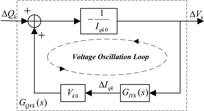
Figure 5. Configuration of the voltage oscillation loop of PMSG-k.
Then, the transfer function model from
where
The proposed model focuses on the dynamic voltage stability under a small signal; in Section 2.2, the voltage oscillation loop of PMSG is derived by linearizing the dynamic equation at a stable equilibrium point. Furthermore, in order to connect all PMSGs, the Q–V sensitivity matrix under the stable equilibrium point can be used as the feedback of the interconnected system.
A linear expression Eq. 16 can be used to represent the relationship between power and voltage.
where
The voltage stability of the power system is affected by active and reactive power. However, at each operating point, active power could be constant to analyze voltage stability considering the relationship between
where
By combining Eqs 15, 17, the interconnected model of the system integrated with multi-PMSGs can be shown in Figure 6.
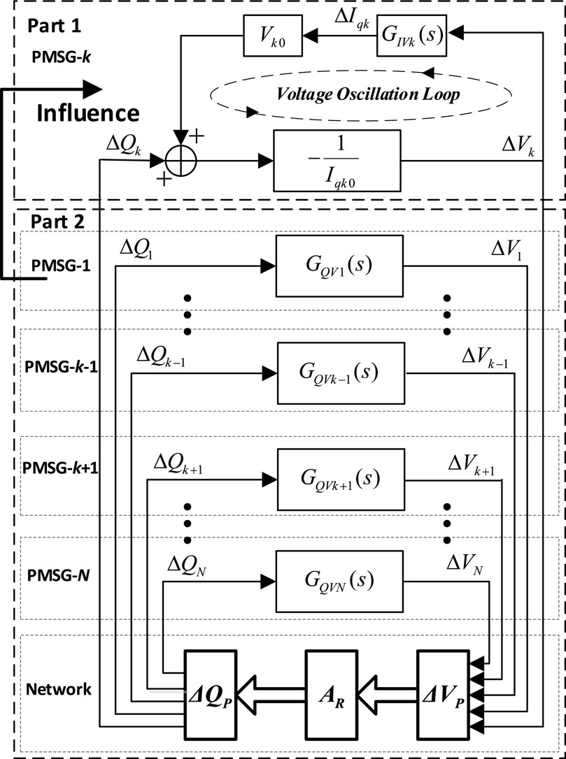
Figure 6. Interconnected linearized model of the system with PMSGs.
There are two parts in Figure 6: part 1 refers to the voltage oscillation loop of PMSG-k and part 2 is the whole power system except PMSG-k. In Figure 6, part 2 has an influence on the voltage oscillation loop of PMSG-k. Moreover, the mathematical expressions of influence from the network and each PMSG except PMSG-k, respectively, are derived in Section 3. All the PMSGs are connected through the network, and
The mathematical expression of
From Figures 5, 6, there is a voltage oscillation loop of PMSG-k, which is affected by the rest of the system. To quantify the influence, the dynamic voltage stability index is proposed, and the voltage stability can be analyzed quantitatively. The more detailed derivation can be shown as follows.
For the loop of PMSG-k in Figure 5, Eq. 15 (Sravan Kumar et al., 2014) can be rewritten as
where,
Then, Eq. 17 can be rewritten as
where subscript k represents the variables of PMSG-k and subscript S represents the variables of all the PMSGs except PMSG-k, S = 1, 2,., k-1, k+1,., N. Furthermore,
From Figure 6, the equation
where
By substituting Eqs 21, 22, the transfer function model from variable
where
Consider
where
By substituting Eqs 20, 24, the representative equation of the voltage oscillation loop of PMSG-k is obtained.
where
Consider
The decomposition of
where
Using Eq. 27,
By substituting Eqs 26, 27, we have
In Eq. 29,
In order to calculate the influence from network and each PMSG except PMSG-k, respectively, the derivation is shown as follows.
By combining Eq 23, 24, we obtain Eqs 30, 31.
Hence,
where
Thus, the dynamic voltage stability index, i.e., the influence from network and each PMSG except PMSG-k, respectively, can be obtained as Eqs 32–33.
where
The formation of the example of the test system with PMSGs is illustrated in Figure 7. There are four SGs and five PMSGs in the power system. The model of the PMSG provided by Li et al. (2012) is adopted, and the values of the parameters of PMSGs are adjusted differently according to the parameters of SGs and loads.

Figure 7. Four-machine two-area system integrated with PMSGs.
In this study case, the oscillation loop of the PMSG-1 is chosen for the calculation of the dynamic index of the rest of the PMSGs. The equation of the chosen voltage oscillation loop of the PMSG-1 is obtained from Eq. 25.
Thus, the following estimation of voltage oscillation mode
By combining the estimation of the oscillation mode and Eq. 33, the dynamic index from each of the rest of the PMSGs to the chosen voltage oscillation loop could be calculated, and the computational results are shown in Table 1. From Table 1, it is evident that PMSG-2, PMSG-3, and PMSG-4 provide the positive index, and PMSG-3 provides the maximum positive index, but PMSG-5 provides the negative index.

Table 1. Computational results of the dynamic index from each of the rest of PMSGs—study case 1.
To validate the effectiveness of the calculation of the dynamic index, each of the rest of the PMSGs is shed subsequently. The results of the non-linear simulation carried out are shown in Figures 8, 9. At t = 1s, the reactive power of PMSG-1 decreases by 0.1 p.u. for 0.2 s. Figures 8, 9 show dynamic responses of reactive power and voltage of PMSG-1 with different PMSGs shed, respectively. The system tends to be unstable after a small disturbance without PMSGs shed. From the calculated voltage stability index in Table 1, the index related to PMSG-5 is negative, which implies the troublemaker of the oscillation. Hence, the dynamic index of different PMSGs can be calculated, and the source of voltage oscillation can be identified using the dynamic index.
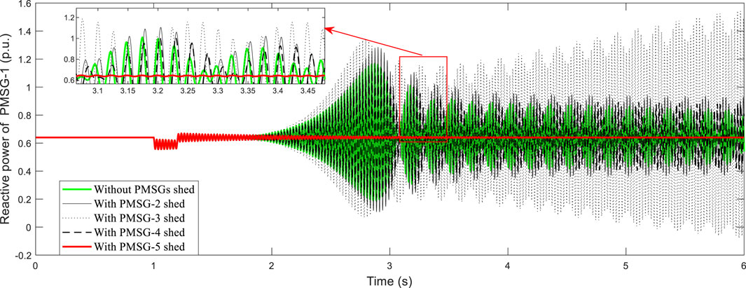
Figure 8. Dynamic responses of reactive power of PMSG-1 with different PMSG shed.

Figure 9. Dynamic responses of voltage of PMSG-1 with different PMSG shed.
PMSG-k is connected to the power system via the transmission line, which is represented by the filtering reactor Xfk. In study case 1, Xf5 is 0.32. In order to evaluate the impact of the reactance of the filtering reactor on the dynamic index, Xf5 is changed from 0.32 to 0.18 in study case 2. Figure 10 shows the variation curve of the dynamic index of PMSG-5. It can be seen that decreasing Xf5 can reduce the amplitude of the negative index supplied by PMSG-5.
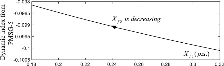
Figure 10. Variation curve of the dynamic index of PMSG-5.
Then, the computational results of the dynamic index are shown in Table 2 after Xf5 is changed to 0.18. Comparing Tables 1, 2, the dynamic index from PMSG-2, PMSG-3, and PMSG-4 is almost constant, but the negative index supplied by PMSG-5 is reduced.

Table 2. Computational results of the dynamic index from each of the rest of PMSGs—study case 2.
In order to study the impact of the decreasing negative index, which is caused by the decreasing reactance to the voltage oscillation loop of PMSG-1, a non-linear simulation is carried out, and the dynamic responses of reactive power and voltage of PMSG-1 under different conditions of filtering reactors are shown in Figure 11.
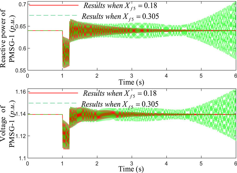
Figure 11. Dynamic responses of reactive power and voltage of PMSG-1 under different conditions of the filtering reactor.
Furthermore, the control parameters of PMSG have been appropriately adjusted, Kp-3 is changed to 1 and Ki-3 is changed to 200. Then, the computational results of the dynamic index are shown in Table 3; it can also be seen that the negative index supplied by PMSG-5 is decreased when Xf5 is changed from 0.305 to 0.18. The results of the non-linear simulation carried out are shown in Figure 12; at t = 1s, the reactive power of PMSG-1 decreases by 0.1 p.u. for 0.2 s. The system tends to be more stable after a small disturbance when Xf5 is 0.18.
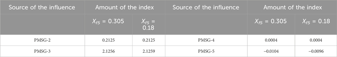
Table 3. Computational results of the dynamic index from each of the rest of PMSGs—study case 2.
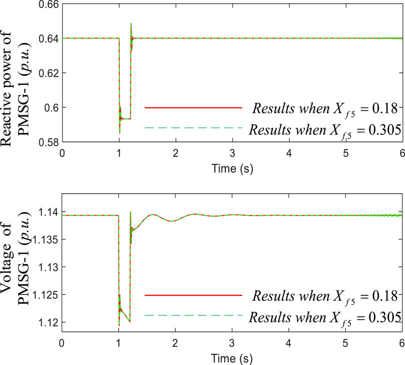
Figure 12. Dynamic responses of reactive power and voltage of PMSG-1 under different conditions of the filtering reactor.
It is evident that decreasing the reactance of the line that connects the source of oscillation to the external grid could reduce the risk of voltage oscillations. The results in Figures 10–12 confirm the correctness of the calculation of the dynamic index.
From the derivation of the voltage oscillation loop shown in Section 2, the parameters Kp-3 and Ki-3 (parameters of part 3 in Figure 4) of the selected PMSG may have an influence on the voltage oscillation loop of the selected PMSGs. The parameters of PMSG-1 in case study 1 are as follows: Kp-3 = 0.1 and Ki-3 = 250.
To examine the influence of the parameters Kp-3 and Ki-3 on the dynamic index, Kp-3 is changed from 0.1 to 0.35 and Ki-3 is changed from 250 to 200 in case study 3. Figure 13 shows the variation curve of the dynamic index of PMSG-5 when the parameters are changing. There are 12 variation curves in Figure 13, the first six curves represent the variation of the dynamic index of PMSG-5 when Kp-3 is constant and Ki-3 is decreasing, while the last six curves represent the variation of the dynamic index when Ki-3 is constant and Kp-3 is increasing under different conditions of Xf5. From Figure 13, it can be seen that the risk of voltage oscillations can be reduced by decreasing Ki-3 and increasing Kp-3. Furthermore, adjusting the parameter Kp-3 and Ki-3 could be more flexible and effective at reducing the negative dynamic index rather than decreasing Xf5.
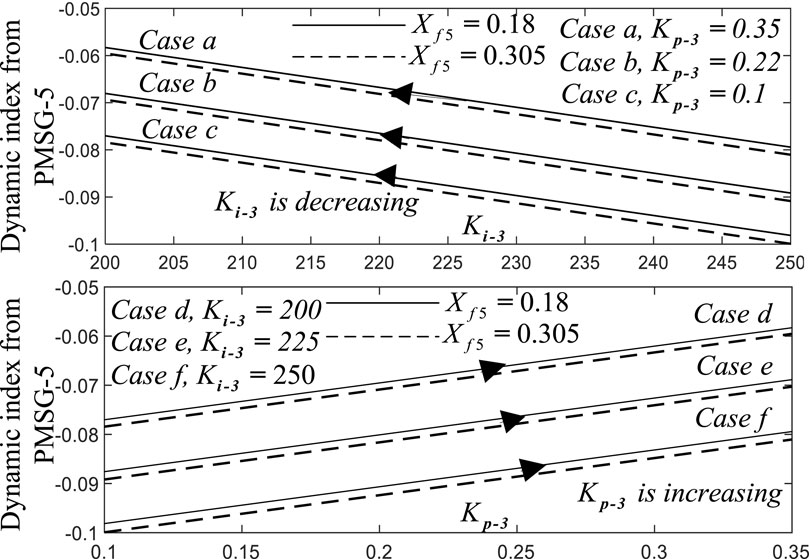
Figure 13. Variation curves of the dynamic index of PMSG-5 when the parameters are changing.
Table 4 shows the computational results of the dynamic index in eight cases with different conditions of Kp-3, Ki-3, Xf4, and Xf5, where H2, H3, H4, and H5 refer to the dynamic index of PMSG-2–PMSG-5, respectively. From Table 3, only PMSG-5 provides the negative index in cases 1–6 and cases 9–12, and the negative index is supplied by PMSG-4 in cases 7 and 8.
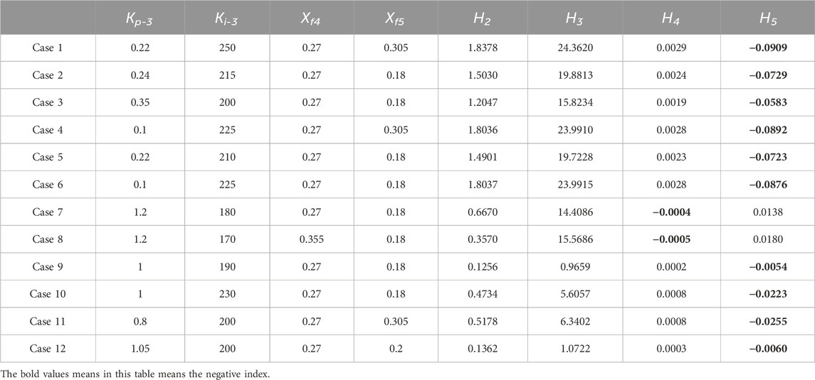
Table 4. Computational results of the dynamic index from each of the rest of PMSGs—study case 3.
To validate the correctness of the calculation of the dynamic index, a non-linear simulation is carried out. Figures 14A–K shows the dynamic responses of PMSG-1 under different cases presented by Table 4, including the dynamic responses of reactive power and voltage. The risk of oscillation increases when the negative index supplied by the source of oscillation (i.e., PMSG-5) increases in cases 1–6 and cases 9–12. Moreover, the source of oscillation is PMSG-4 in cases 7 and 8, and the system tends to be unstable, obviously after disturbance in case 8, which has a larger negative index. Hence, the correctness of the calculation is verified, and the dynamic voltage stability index can be applied under different conditions.
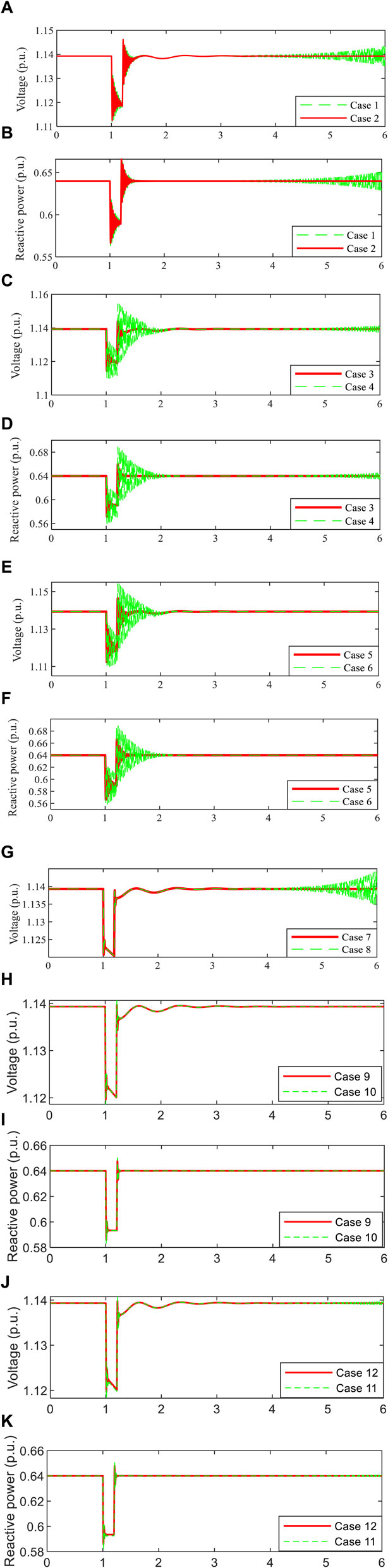
Figure 14. Dynamic responses of voltage and reactive power of PMSG-1 under different cases.,
This paper presents a dynamic voltage stability index based on the voltage oscillation loop for a power system with multi-PMSGs, and the correctness of the index is confirmed by the test system. The primary contributions are listed as follows:
(1) The voltage oscillation loop existing in the PMSGs is derived through merging the dynamic model of PMSGs. Furthermore, the Q–V sensitivity matrix is used as feedback to connect all the PMSGs, and then the model applied to study voltage stability is obtained.
(2) The dynamic interaction on voltage stability for the power system integrated with multi-PMSGs could be quantified by applying the dynamic index proposed in this paper. The influence of the rest of each PMSG on the voltage oscillation loop of the selected PMSG could be calculated, and the source of voltage oscillation that provides the maximum negative index could be identified.
(3) The proposed dynamic voltage stability index is able to be applied to direct the control parameters adjustment of selected PMSG to ensure that voltage stability is maintained under different conditions.
The main drawback of this strategy is that it is based on the model of wind power grid-connected systems to quantitatively analyze the dynamic voltage stability among PMSGs. This method is more suitable for offline analysis of the system and makes it difficult to conduct real-time online quantitative analysis of the voltage characteristics of wind power grid-connected systems. Therefore, the authors will conduct research on online quantitative analysis of the dynamic voltage stability of the wind power grid-connected system based on measurement data in the next step.
The original contributions presented in the study are included in the article/Supplementary material; further inquiries can be directed to the corresponding author.
LC: methodology and writing–original draft. JW: writing–review and editing. XK: writing–review and editing. ZH: writing–review and editing. DA: writing–review and editing.
The author(s) declare that no financial support was received for the research, authorship, and/or publication of this article.
Authors JW and XK were employed by the Northwest Branch of State Grid Corporation of China.
The remaining authors declare that the research was conducted in the absence of any commercial or financial relationships that could be construed as a potential conflict of interest.
All claims expressed in this article are solely those of the authors and do not necessarily represent those of their affiliated organizations, or those of the publisher, the editors, and the reviewers. Any product that may be evaluated in this article, or claim that may be made by its manufacturer, is not guaranteed or endorsed by the publisher.
Adams, J., Pappu, V. A., and Dixit, A. (2012). "Ercot experience screening for Sub-Synchronous Control Interaction in the vicinity of series capacitor banks," IEEE Power and Energy Society General Meeting, San Diego, CA, pp. 1–5.
Baa Wafaa, M., and Dessaint, L. (2018). Approach to dynamic voltage stability analysis for DFIG wind parks integration. IET Renew. Power Gener. 12 (2), 190–197. doi:10.1049/iet-rpg.2016.0482
Belkhier, Y., and Oubelaid, A. (2024). Novel design and adaptive coordinated energy management of hybrid fuel-cells/tidal/wind/PV array energy systems with battery storage for microgrids. Energy Storage 6, e556. doi:10.1002/est2.556
Chi, Y., and Xu, Y. (2020). Multi-stage coordinated dynamic VAR source placement for voltage stability enhancement of wind-energy power system. IET Generation, Transm. Distribution 14 (6), 1104–1113. doi:10.1049/iet-gtd.2019.0126
Dashtdar, M., et al. (2022). "Protection of DC microgrids based on frequency domain analysis using fourier transform," IEEE 3rd KhPI week on advanced Technology (KhPIWeek), Kharkiv, Ukraine, pp. 1–6.
Du, W., Bi, J., Cao, J., and Wang, H. F. (2016). A method to examine the impact of grid connection of the DFIGs on power system electromechanical oscillation modes. IEEE Trans. Power Syst. 31 (5), 3775–3784. doi:10.1109/tpwrs.2015.2494082
Du, W., Chen, X., and Wang, H. F. (2017). Power system electromechanical oscillation modes as affected by dynamic interactions from grid-connected PMSGs for wind power generation. IEEE Trans. Sustain. Energy 8 (3), 1301–1312. doi:10.1109/tste.2017.2677094
Erlich, I. (2017). "Control challenges in power systems dominated by converter interfaced generation and transmission technologies," NEIS 2017; Conference on Sustainable Energy Supply and Energy Storage Systems, 21-22 September 2017, Hamburg, Germany, IEEE, 1–8.
García, H., Segundo, J., Rodríguez-Hernández, O., Campos-Amezcua, R., and Jaramillo, O. (2018). Harmonic modelling of the wind turbine induction generator for dynamic analysis of power quality. Energies 11 (1), 104. doi:10.3390/en11010104
Khosravi, N., Baghbanzadeh, R., Oubelaid, A., Tostado-Véliz, M., Bajaj, M., Hekss, Z., et al. (2023). A novel control approach to improve the stability of hybrid AC/DC microgrids. Appl. Energy 344, 121261. doi:10.1016/j.apenergy.2023.121261
Kroposki, B., Johnson, B., Zhang, Y., Gevorgian, V., Denholm, P., Hodge, B. M., et al. (2017). Achieving a 100% renewable grid: operating electric power systems with extremely high levels of variable renewable energy. IEEE Power Energy Mag. 15 (2), 61–73. doi:10.1109/mpe.2016.2637122
Li, S., Haskew, T. A., Swatloski, R. P., and Gathings, W. (2012). Optimal and direct-current vector control of direct-driven PMSG wind turbines. IEEE Trans. Power Electron. 27 (5), 2325–2337. doi:10.1109/tpel.2011.2174254
Liu, H., and Sun, J. (2014). Voltage stability and control of offshore wind farms with AC collection and HVDC transmission. IEEE J. Emerg. Sel. Top. Power Electron. 2 (4), 1181–1189. doi:10.1109/jestpe.2014.2361290
Liu, H., Xie, X., He, J., Xu, T., Yu, Z., Wang, C., et al. (2017). Subsynchronous interaction between direct-drive PMSG based wind farms and weak AC networks. IEEE Trans. Power Syst. 32 (6), 4708–4720. doi:10.1109/tpwrs.2017.2682197
Liu, J., Xu, Y., Dong, Z. Y., and Wong, K. P. (2018). Retirement-driven dynamic VAR planning for voltage stability enhancement of power systems with high-level wind power. IEEE Trans. Power Syst. 33 (2), 2282–2291. doi:10.1109/tpwrs.2017.2732441
Ou, R., Xiao, X., Zou, Z., Zhang, Y., and Wang, Y. (2016). Cooperative control of SFCL and reactive power for improving the transient voltage stability of grid-connected wind farm with DFIGs. IEEE Trans. Appl. Supercond. 26 (7), 1–6. doi:10.1109/tasc.2016.2574344
Qian, Y., Yuan, X., and Zhao, M. (2016). Analysis of voltage control interactions and dynamic voltage stability in multiple wind farms. 2016 IEEE Power Energy Soc. General Meet., 1–5. doi:10.1109/PESGM.2016.7741676
Rakhshani, E., Gusain, D., Sewdien, V., Rueda Torres, J. L., and Van Der Meijden, M. A. M. M. (2019). A key performance indicator to assess the frequency stability of wind generation dominated power system. IEEE Access 7, 130957–130969. doi:10.1109/access.2019.2940648
Rawat, M. S., and Vadhera, S. (2020). Probabilistic steady state voltage stability assessment method for correlated wind energy and solar photovoltaic integrated power systems. Energy Technol. 9 (2), 2000732. doi:10.1002/ente.202000732
Sanchez, A. G., Molina, M. G., and Rizzato Lede, A. M. (2012). Dynamic model of wind energy conversion systems with PMSG-based variable-speed wind turbines for power system studies. Int. J. hydrogen energy 37 (13), 10064–10069. doi:10.1016/j.ijhydene.2011.12.077
Sravan Kumar, V. S., Krishna Reddy, K., and Thukaram, D. (2014). Coordination of reactive power in grid-connected wind farms for voltage stability enhancement. IEEE Trans. Power Syst. 29 (5), 2381–2390. doi:10.1109/tpwrs.2014.2300157
Su, G., Xu, L., Du, W., Chen, C., Ji, Y., and Wang, H. (2019). Power system dynamic voltage stability affected by open-loop modal coupling between DFIG-based wind farms and IM loads. J. Eng. 2019 (16), 2514–2519. doi:10.1049/joe.2018.8579
Tourandaz Kenari, M., Sepasian, M. S., and Setayesh Nazar, M. (2019). Probabilistic assessment of static voltage stability in distribution systems considering wind generation using catastrophe theory. IET Generation, Transm. Distribution 13 (13), 2856–2865. doi:10.1049/iet-gtd.2018.5497
Venkatesh, B., Rost, A., and Chang, L. (2007). Dynamic voltage collapse index— wind generator application. IEEE Trans. Power Deliv. 22 (1), 90–94. doi:10.1109/tpwrd.2006.887097
Vittal, E., O'Malley, M., and Keane, A. (2010). A steady-state voltage stability analysis of power systems with high penetrations of wind. IEEE Trans. Power Syst. 25 (1), 433–442. doi:10.1109/tpwrs.2009.2031491
Wang, L., Xie, X., Jiang, Q., Liu, H., Li, Y., and Liu, H. (2015b). Investigation of SSR in practical DFIG-based wind farms connected to a series-compensated power system. IEEE Trans. Power Syst. 30 (5), 2772–2779. doi:10.1109/tpwrs.2014.2365197
Wang, X., Wei, X., and Meng, Y. (2015a). Experiment on grid-connection process of wind turbines in fractional frequency wind power system. IEEE Trans. Energy Convers. 30 (1), 22–31. doi:10.1109/tec.2014.2358498
Keywords: dynamic interaction, permanent magnet synchronous generators, voltage stability index, voltage oscillation loop, power systems
Citation: Cheng L, Wang J, Ke X, Han Z and Ai D (2024) Voltage stability analysis considering dynamic interaction for power systems integrated with multi-PMSGs. Front. Energy Res. 12:1417360. doi: 10.3389/fenrg.2024.1417360
Received: 14 April 2024; Accepted: 04 June 2024;
Published: 03 July 2024.
Edited by:
Joshuva Arockia Dhanraj, Dayananda Sagar University, IndiaReviewed by:
Ioan Viorel Banu, University of Bacău, RomaniaCopyright © 2024 Cheng, Wang, Ke, Han and Ai. This is an open-access article distributed under the terms of the Creative Commons Attribution License (CC BY). The use, distribution or reproduction in other forums is permitted, provided the original author(s) and the copyright owner(s) are credited and that the original publication in this journal is cited, in accordance with accepted academic practice. No use, distribution or reproduction is permitted which does not comply with these terms.
*Correspondence: Lin Cheng, NDE5MDMzMTA2QHFxLmNvbQ==
Disclaimer: All claims expressed in this article are solely those of the authors and do not necessarily represent those of their affiliated organizations, or those of the publisher, the editors and the reviewers. Any product that may be evaluated in this article or claim that may be made by its manufacturer is not guaranteed or endorsed by the publisher.
Research integrity at Frontiers
Learn more about the work of our research integrity team to safeguard the quality of each article we publish.