 Zhuan Zhao
 Haoran Li2
 Shuhuai Shi
- 1Zhengzhou Electric Power College, Zhengzhou, China
- 2State Grid Zhoukou Electric Power Supply Company, Zhoukou, China
- 3Henan Jiuyu Epri Electric Power Technology Co., Ltd., Zhengzhou, China
- 4State Grid Henan Electric Power Research Institute, Zhengzhou, China
- 5China Power New Life Town Technology Co., Ltd., Beijing, China
In DC transmission and distribution systems, both unipolar and bipolar transmission modes exist, and DC transformers used in these systems are also available in either unipolar or bipolar configurations. In actual systems, due to requirements such as economy, land occupation, and reliability, there is a tendency to use a system with unipolar input and bipolar output. However, the bipolar loads, if unbalanced, will lead to increased equipment costs and voltage imbalance, causing power quality problems. This paper defines the Power Unbalance Factor (PUF) to describe the power quality of the studied DC transmission system and presents an improved DC transformer topology based on a power balancing system. This topology realizes bipolar voltage balance and improves the power quality of the DC transmission system when the load is unbalanced. The influence of the proposed solution on the power design of the DC system is demonstrated through theoretical analysis, and its effectiveness for improving the DC power quality is verified by both simulations in MATLAB/Simulink environment and physical experiments. When the power electronic transformer needs to be overloaded, the proposed topology can reduce the design power of the two branches by using the difference power, which is economical.
1 Introduction
The need to adjust the energy structure and develop sustainable green energy on a large scale is imperative due to the exhaustion of mainstream fossil energy and the serious problem of environmental pollution (Chen et al., 2013). The application of new renewable energies, such as water, wind, light, and geothermal energy, is an important measure to achieve environmental protection and sustainable economy development worldwide. The European Union has set a higher development goal, requiring renewable energy consumption to reach 20.0% of energy consumption and 30.0% of total power generation by 2020 (Wang et al., 2018; Yao et al., 2014). To reduce the use of fossil energy, promote multi-energy complementation, and achieve comprehensive energy utilization of the power system, it is necessary to develop new technologies related to power grid equipment (Wang et al., 2013; Xiong et al., 2021a, Xiong et al., 2021b) and reduce the loss and transformation of each link of power generation, transmission, and distribution (Zhang et al., 2018; Xiong et al., 2021a, Xiong et al., 2021b). One effective complement to the AC system can be seen in the DC system, which has advantages such as low loss, less reactive power, and convenient access to new energy, especially with the continuous development of fully-controlled semiconductor devices such as insulated-gate bipolar transistors (IGBTs) (Zhao et al., 2008; Engel et al., 2014). DC power electronic transformer has the advantages of electrical isolation, efficient energy conversion, fast dynamic response, flexible control, small size, light weight and easy expansion and integration (Lin, 2016; Xiong et al., 2020). These advantages make DC power electronic transformers have a wide range of applications in distributed power systems, renewable energy access, DC micro-grid and other fields.
However, power quality is a key issue in the transmission, distribution, and consumption of power systems that affects the stability, security, and economy of the system (Kenzelmann et al., 2014; Xiong et al., 2021a, Xiong et al., 2021b). In comparison with the AC system, the power quality of the DC transmission and distribution system is usually better, as the DC voltage does not change as frequently as in the AC system but is maintained approximately at a rated value, and there are no traditional power quality problems caused by harmonics and interference (Akagi and Kitada, 2011). However, if the rationale behind the definition of power quality is considered to be describing the quality of the power supply, either in the form of AC or DC, with a special focus on the waveforms of voltages and currents, then the power quality of a DC system can be reflected similarly by the deviation between the ideal and real-time waveforms in such a system. Under such a premise, the power quality in a DC transmission and distribution system is closely related to the topology, control, modulation method, and application scenarios of power electronic converters, which are important elements to form the DC system.
Unipolar and bipolar hybrid transmission is one of the typical application scenarios for DC transmission and distribution systems (Jovcic and Ool, 2010). Specifically, unipolar transmission is used on the medium-voltage side of medium-voltage DC distribution networks to reduce transmission costs and the land area used (Gowaid et al., 2015). Meanwhile, bipolar transmission is used on the low-voltage side as it can maximize the reliability of the power supply and reduce the insulation design requirements of the system (Li et al., 2012). Such systems mostly adopt two DC transformers in series on the input side and in parallel on the output side, forming an input-series output-parallel (ISOP) topology (Ooi and Wang, 1991; Xiong et al., 2016; Falcones S et al., 2013), which requires double the cost of equipment. Moreover, the voltage instability caused by the load imbalance of the two poles is the biggest problem faced by this application scenario, which is a great challenge to the power quality of DC transmission systems.
Focusing on the aforementioned issues, this paper uses the degree of voltage imbalance between the two poles as an indicator of the DC system’s power quality. Such an indicator is crucial for evaluating and improving the power transmission in the DC system. On this basis, a novel topology is proposed for enhancing the power quality of the unipolar-input-bipolar-output system, by forcing load power balancing. Such a balance is implemented by properly controlling the dual active bridge (DAB) circuit in parallel with the two loads on different poles. Theoretical analysis proves the improvement of DC system power design by adopting the topology in the case of unbalanced loads, which are commonly encountered in practical applications. This paper introduces the structure and control method of the topology in detail, and sets the boundary conditions of the scene in detail, and gives the detailed design parameters of the design capacity of the topology according to the boundary conditions. By comparing the design parameters in different scenarios, the economy of the topology is proved. Finally, the feasibility of the new topology is verified by simulation results in the MATLAB/Simulink environment as well as experimental results based on a physical platform.
2 Studied system and power unbalance factor
Figure 1 illustrates the most well-established topology for unipolar to bipolar conversion. This topology utilizes two DC transformers connected in parallel at a single pole, with their outputs connected in series to two loads, while the ground wire is led out from the middle. With reference to Figure 1, Load 1 and Load 2 represent two load units, which may consist of a single load, a load group, or a power supply line of the same voltage level. As seen from the diagram, the power of Load 1 is transmitted by DC transformer 1, and the power of Load 2 is transmitted by DC transformer 2. Both loads are independent of each other, and there is no power coupling between the two DC transformers. The two DC transformers share the same input side with input voltage Vin, i.e., the unipolar input is used, while the two loads on the output side are grounded with no power interaction between them, forming a positive pole (with voltage Udc/2) and a negative pole (with voltage -Udc/2). This topology is equivalent to two separate monopole-to-monopole power transformation legs.
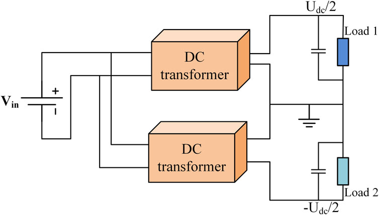
Figure 1. Principle diagram of the studied unipolar-input-bipolar-output DC system.
Power imbalance refers to the imbalance of power output or consumption among various parts or components in a system. In a three-phase power system, if the three-phase current or voltage is not balanced, it will lead to power imbalance. In the DC system, if two circuits are connected in parallel, the situation similar to the AC system will also occur. When both loads are balanced, the rated power per pole yields Pout+ = Pout- = P. The maximum total power of the load on the bipolar side is designed to be 2P, considering the unbalance of the DC system. Then, the power imbalance between the two load ports is defined to reflect the power quality in the DC system. Since Load 1 and Load 2 are connected in series, the imbalance of load, voltage, and power is equivalent. If the voltage balance between the positive and negative poles is achieved, it also means that the power of the two poles is equal. To this end, in this paper, the power unbalance factor (PUF) is defined as Eq. 1
where Pload is the load power of the pole (either positive or negative).
The PUF value indicates the degree of power imbalance in the system, with η = 0 representing perfect balance. When the value of η is positive, it means that the power of the load exceeds the rated power at load balance; when it is negative, it means that the power of the load is lower than the rated power at load balance. The PUF value can be used as an essential indicator of the system’s stability and efficiency, enabling effective management of the system’s performance. By utilizing this topology and PUF value, we can establish a more stable and efficient power conversion system, reducing power loss and ensuring reliable and consistent operation.
It is noted that though such a DC system is usually designed to be symmetrical in order to maximize power delivery efficiency and reduce cost, in practice, it is common that loads are unbalanced. In those cases, the PUF value is different than 0, and the power quality is compromised.
3 Research on topology and control method of DC transformer
In this Section, a novel configuration is developed to improve the power quality of the unipolar-to-bipolar power conversion under unbalanced load conditions, by incorporating a system that enables load power balancing. A detailed analysis of the physical implementation and control principles is performed in the following section.
3.1 Physical implementation
Figure 2 shows the detailed implementation of DC transmission system, realizing the principle diagram in Figure 1 and incorporating a power balance system to tackle the possible presence of load imbalance. The input side (medium-voltage side) is powered by a voltage source converter, while the two loads correspond to the positive and negative poles on the output side. The DC transformer for each pole consists of multiple DAB modules that are connected in series on the input side and in parallel on the output side, with the number of DAB modules determined by the voltage level and required power. The medium-voltage DC network transfers power to the load through the DC transformers, keeping the voltages of the two loads equal under the nominal condition with balanced loads. However, when the loads are imbalanced, the voltages of the two ports become unequal.
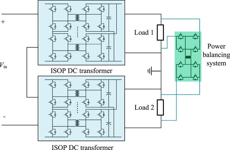
Figure 2. Proposed topology with power balance system.
To address this issue, the proposed topology incorporates a power balancing system (PBS) that enables power balancing between loads. As shown in Figure 2, such a PBS is implemented by connecting a DAB, whose ports are in parallel with the two loads, into the original system. This allows for bidirectional power flow between the two loads. Specifically, the PBS transfers power from the high-voltage port to the low-voltage one, achieving voltage balance between the two ports. Since the PBS handles the power difference between the two ports, its design capacity only needs to be half the power difference between the two.
3.2 Control method
3.2.1 DC transformer control
The main circuit topology of the DC transformer features an ISOP structure, with multiple DAB circuits connected in series on the input side to reduce the withstand voltage of each module and in parallel on the output side to reduce the current of each module. The phase shift control strategy is employed in DAB modules, with each module controlled separately. Given that each module on the input side is connected in series, it is essential to ensure that all modules are voltage balanced. Therefore, the phase shift angle of each module is adjusted by the input voltage and the output voltage, as shown in Figure 3. Specifically, the control system of the ISOP DC transformer comprises an input voltage loop and an output voltage loop, each adopting a proportional-integral (PI) controller, in order to generate the phase shift angle of each module. Finally, the gate signals of the pertinent switches are generated based on the real-time phase shift angle (not shown here for brevity).

Figure 3. Control diagram of DC transformer.
3.2.2 Power balancing control
To achieve voltage balance between the two ports, the proposed PBS is used to transfer unbalanced power. Given that the two loads are connected in series, the power balance system needs to meet the two conditions of bidirectional power flow and electrical isolation. To this end, the DAB is employed to implement the power balance system, with the control diagram shown in Figure 4.
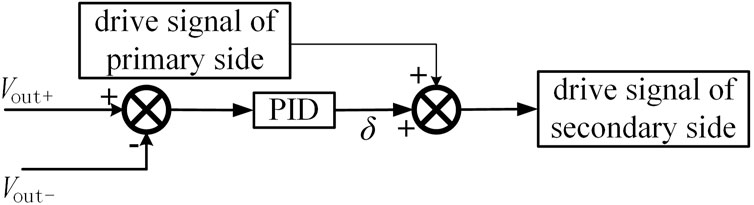
Figure 4. Control diagram of proposed PBS.
Unlike the control strategy of the main circuit that aims to transfer the power from the input to the output, the power balance system needs to achieve voltage balancing of the two ports. As such, the phase shift angle is determined by the voltage difference between the two ports, using a proportional-integral-derivative (PID) controller. Following this, the drive signal of the DAB secondary side can be generated.
4 System power design
In this Section, the system power design is discussed for the sample system in Figure 2, with two scenarios being used to reveal the impact of the proposed PBS. In Scenario 1, the loads operate within their respective set intervals, and it will be shown that the topology with PBS does not offer any advantage in terms of power design compared to the topology without PBS. However, in Scenario 2, where the operating power of one load may exceed the rated power, the topology with PBS has significant advantages in power design. For both cases, the total operating power of Load 1 and Load 2 will not exceed the rated power of the system.
4.1 Scenario 1: 0 ≤ Pout+ ≤ P, 0 ≤ Pout- ≤ P
The topology in Figure 2 contains two DC transformers, each of which is constructed from ISOP structures, but neither of them is loaded with power more than P, namely, neither Pout+ nor Pout- will exceed the power rating of their respective lines. Therefore, both Load 1 and Load 2 only operate within their respective set intervals, and the two lines will not be standby for each other, nor will they be overloaded.
At this time, the design power of each ISOP of the DC transformer in the topology is P, and the design power of the DC transformer is 2P. Additionally, if the proposed scheme with the PBS is used, the PBS is required to handle the differential power. Hence, the total equipment design power of the system, including the DC transformer and the PBS, is Eq. 2:
where ηL1 is the PUF value of Load 1, and ηL2 is the PUF value of Load 2.
It is seen that in the setting of scenario 1, since the two loads are not overloaded, there will always be an extra PBS handling the unbalanced power, and the total design power of the system will be greater than that without the proposed PBS (2P). The proposed PBS in this scenario has no advantage in terms of system power design.
4.2 Scenario 2: 0 ≤ Pout+ +Pout- ≤ 2P, 0 ≤ Pout+ ≤ 2P, 0 ≤ Pout- ≤ 2P
In this scenario, the upper power limits of both Load 1 and Load 2 are 2P, indicating a certain load may be overloaded with the elapse of operating time. In practice, this suggests that a line will suddenly increase its load, or that two lines will be standby for each other.
In the first case, when the traditional topology without the proposed PBS is used, the design power of ISOP modules in each DC transformer needs to be designed to meet the overload power, considering the upper power limit of loads. When Pout+ ≥ P and Pout- ≤ P, the positive DC transformer is overloaded, and its power is given by Eq. 3
where
Similarly, when Pout+ ≤ P and Pout- ≥ P, the negative DC transformer is overloaded, and its corresponding power is Eq. 4
where
The total design power of the device needs to be the sum of the positive and negative poles, yielding Eq. 5
In the second case, when the proposed scheme is used, since the sum of the power of Load 1 and Load 2 does not exceed 2P, the design power of each ISOP is just half of the total power, namely, P. The PBS handles the power difference between the positive and negative poles. Accordingly, when Pout+ ≥ P and Pout- ≤ P, the design power of the system is Eq. 6
When Pout+ ≤ P and Pout- ≥ P, the design power of the system is Eq. 7
Since the system needs to meet the demand of the maximum differential power, we have Eq. 8
Comparing Eqs 5, 8, it is seen that the PBS system in Scenario 2 has obvious advantages in terms of power design. Besides, with the increase of load imbalance, this advantage becomes more obvious, as illustrated by Table 1.

Table 1. Comparison of system design power between two topologies.
5 Verification
In this Section, simulation results based on MATLAB/Simulink, as well as experimental results on a physical platform, have been used to demonstrate the effectiveness of the PBS in balancing the voltage across two loads and thus improving the power quality of the DC system.
5.1 Simulation verification
Simulations were carried out using MATLAB/Simulink to verify the performance of the PBS. With reference to the system topology in Figure 1, the simulation setup involved a unipolar input voltage of 20.0 kV on the medium-voltage side of the system, while the low-voltage side was bipolar with an output voltage of ±375.0 V. The simulation results depicted in Figure 5 showed that when both loads 1 and 2 were equal and set to 10.0 Ω, the system functioned correctly without the need for the PBS. However, when Load 1 was increased to 20.0 Ω while Load 2 remained at 10.0 Ω, the voltage of Load 1 was twice that of Load 2 in the absence of the proposed PBS, causing the system to become voltage unbalanced, as shown in Figure 6.
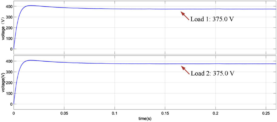
Figure 5. Simulated voltage waveforms in the absence of the PBS when Load 1 and Load 2 have the same impedance of 10.0 Ω.
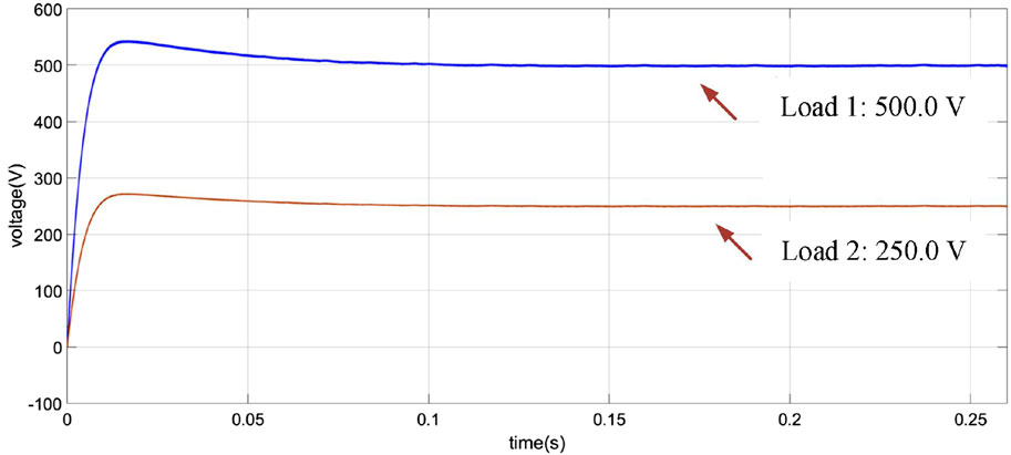
Figure 6. Simulated voltage waveforms in the absence of the PBS when Load 1 is 20.0 Ω while Load 2 is 10.0 Ω.
After the proposed PBS was added, the system topology becomes Figure 2, and the simulation results depicted in Figure 7A show that the voltages of two ports were initially inconsistent when Load 1 was 20.0 Ω while Load 2 was 10.0 Ω. However, after an adjustment period of 0.15 s, the voltage of both ports approached the same value, which was 375.0 V. Figure 7B shows an enlarged portion of the waveforms in Figure 7A, where the voltage fluctuation after the system was stabilized was within 1.0%, showing the effectiveness of the proposed PBS in this situation.
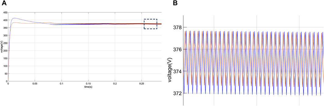
Figure 7. Simulated voltage waveforms in the presence of the PBS when Load 1 is 20.0 Ω while Load 2 is 10.0 Ω. (A) Overall waveforms. (B) Zoomed-in waveforms.
Similarly, the simulation results shown in Figure 8, corresponding to the case the case where Load 1 is 10.0 Ω and Load 2 is 20.0 Ω, demonstrate again the effect of the proposed PBS on system voltage balancing. Moreover, the PBS could achieve bidirectional flow of power, since in this case power flowed to the upper port through the PBS. The voltage of the two ports approached the same value after a period of adjustment.
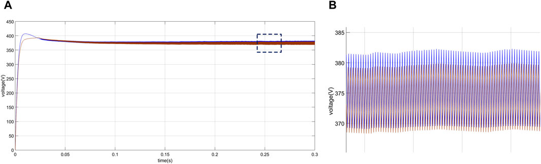
Figure 8. Simulated voltage waveforms in the presence of the PBS when Load 1 is 10.0 Ω while Load 2 is 20.0 Ω. (A) Overall waveforms. (B) Zoomed-in waveforms.
5.2 Experimental verification
To validate the effectiveness of the PBS, experimental tests were conducted on a physical platform comprising a dSPACE system, DC transformer hardware circuits, a DC power supply, and DC loads. The experimental setup involved using a programmable DC source with protection as the DC power supply and pure resistive DC electronic loads as the output port loads. The single-stage input side, the bipolar output side, and the PBS, are composed of H-bridge submodules and isolation transformers (see circuit board in Figure 9). Each H bridge independently uses a circuit board including the power modules and driver modules, and the number of H bridges in the cascaded H bridges can be flexibly selected. The experimental platform parameters are shown in Table 2.
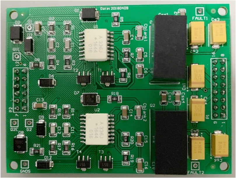
Figure 9. H-bridge submodule circuit board.
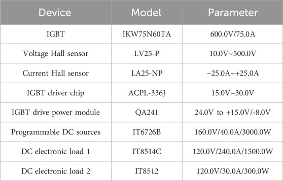
Table 2. Devices and parameters used in the experiment.
Specifically, the H-bridge structure and its front-end half-bridge protection circuit are composed of upper and lower IGBT half-bridge units. The H-bridge circuit used discrete IGBT components, IKW75N60TA of Infineon. The driving circuit was designed to provide IGBT turn-on voltage and ensure IGBT turn-off voltage. A plurality of H-bridge modules formed the structure shown in Figure 2.
During the experiment, Load 1 was set to 75.0 Ω and Load 2–150.0 Ω. An input voltage of 50.0 V was supplied at time t0. Due to the different loads, when there is no power balance system, the voltage of the two ports will be inconsistent, that is, the power imbalance problem of the DC system defined in this paper. According to the waveforms of Figures 10, 11, the system incorporates a power balancing system. The experimental results depicted in Figures 10, 11 showed that the PBS system was capable of bipolar balanced output. After a short transient, the output voltages of the two loads become equal in magnitude (30.0V). At this time, the positive current was 0.4 A, and the negative current was 0.2 A, which was consistent with the ratio of the two loads.
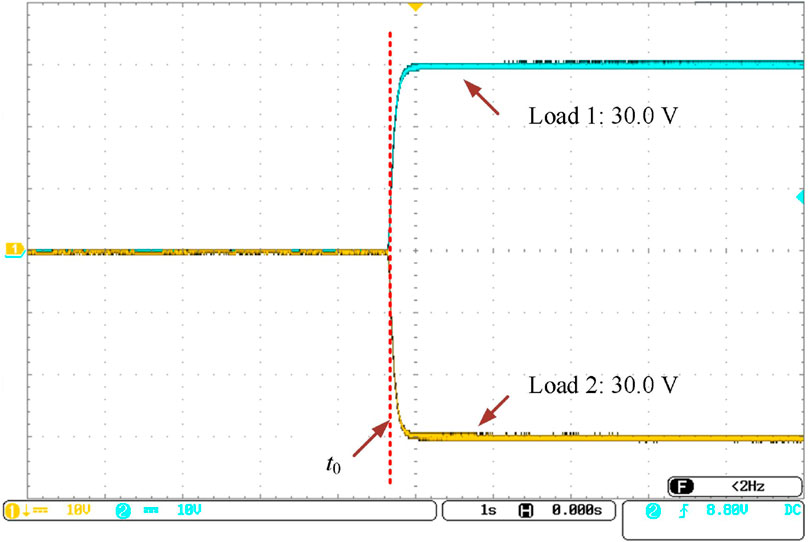
Figure 10. Experimental voltage waveforms of loads in the presence of the PBS when Load 1 is 75.0 Ω while Load 2 is 150.0 Ω.
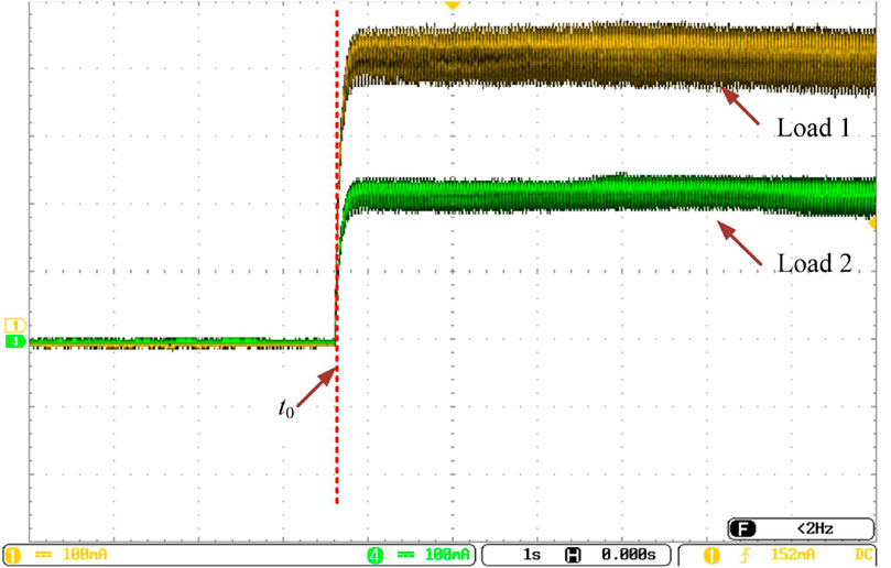
Figure 11. Experimental current waveforms of loads in the presence of the PBS when Load 1 is 75.0 Ω while Load 2 is 150.0 Ω.
In summary, both the simulation and experimental results demonstrated the effectiveness of the PBS in balancing the voltage across two loads and improving the power quality of the DC system. The experimental setup and simulation model could be used as a reference for future research on power balancing systems.
6 Conclusion
In this paper, a novel DC transformer and power balance topology is proposed to address the problem of load imbalance possibly present in a DC distribution network. Our proposed topology achieves voltage/power balancing through an actively-controlled PBS, and its feasibility has been verified. Specifically, in the DC/DC conversion scenario where the input is unipolar and the output is bipolar, the proposed topology balances the output voltage of the positive and negative poles and effectively mitigates the impact of load imbalance on the system operation. The proposed topology is robust and able to maintain power balance under various operating conditions. Overall, the findings demonstrate the potential of the proposed topology to address one of the major challenges faced by the DC transmission and distribution system. In the second scenario, the proposed topology can reduce the design difference power by 50.0%, which means that the greater the difference between the output of the two poles, the greater the advantage of the topology.
Data availability statement
The original contributions presented in the study are included in the article/Supplementary Material, further inquiries can be directed to the corresponding author.
Author contributions
ZZ: Formal Analysis, Software, Supervision, Writing–original draft, Writing–review and editing. HL: Conceptualization, Supervision, Writing–review and editing. FS: Data curation, Investigation, Writing–review and editing. SS: Conceptualization, Formal Analysis, Methodology, Project administration, Software, Validation, Visualization, Writing–original draft, Writing–review and editing. DW: Formal Analysis, Investigation, Validation, Writing–review and editing. JZ: Data curation, Project administration, Writing–original draft. CW: Conceptualization, Validation, Writing–review and editing.
Funding
The author(s) declare that no financial support was received for the research, authorship, and/or publication of this article.
Conflict of interest
Author HL was employed by State Grid Zhoukou Electric Power Supply Company. Author FS was employed by Henan Jiuyu Epri Electric Power Technology Co., Ltd. Author CW was employed by China Power New Life Town Technology Co., Ltd.
The remaining authors declare that the research was conducted in the absence of any commercial or financial relationships that could be construed as a potential conflict of interest.
Publisher’s note
All claims expressed in this article are solely those of the authors and do not necessarily represent those of their affiliated organizations, or those of the publisher, the editors and the reviewers. Any product that may be evaluated in this article, or claim that may be made by its manufacturer, is not guaranteed or endorsed by the publisher.
References
Akagi, H., and Kitada, R. (2011). Control of a modular multilevel cascade BTB system using bidirectional isolated DC/DC converters. IEEE Trans. Power Electron. 26, 2457–2464. doi:10.1109/ECCE.2010.5617703
Chen, D., Xu, L., and Yao, L. (2013). DC voltage variation based autonomous control of DC microgrids. IEEE Trans. Power Deliv. 28, 637–648. doi:10.1109/TPWRD.2013.2241083
Engel, S. P., Stieneker, M., Soltau, N., Rabiee, S., Stagge, H., and Doncker, R. W. D. (2014). Comparison of the modular multilevel DC converter and the dual-active bridge converter for power conversion in HVDC and MVDC grids. IEEE Trans. Power Electron. 30, 124–137. doi:10.1109/TPEL.2014.2310656
Falcones, S., Ayyanar, R., and Mao, X. (2013). A DC–DC multiport-converter-based solid-state transformer integrating distributed generation and storage. IEEE Trans. Power Electron. 28 (5), 2192–2203. doi:10.1109/TPEL.2012.2215965
Gowaid, I. A., Adam, G. P., Massoud, A. M., Ahmed, S., Holliday, D., and Williams, B. W. (2015). Quasi two-level operation of modular multilevel converter for use in a high-power DC transformer with DC fault isolation capability. IEEE Trans. Power Electron. 30 (1), 108–123. doi:10.1109/TPEL.2014.2306453
Jovcic, D., and Ooi, B. T. (2010). Developing DC transmission networks using DC transformers. IEEE Trans. Power Deliv. 25 (4), 2535–2543. doi:10.1109/TPWRD.2010.2052074
Kenzelmann, S., Rufer, A., Dujic, D., Canales, F., and Novaes, Y. R. D. (2014). Isolated DC/DC structure based on modular multilevel converter. IEEE Trans. Power Electron. 30, 89–98. doi:10.1109/TPEL.2014.2305976
Li, Z., Wang, P., Zhu, H., Chu, Z., and Li, Y. (2012). An improved pulse width modulation method for chopper-cell-based modular multilevel converters. IEEE Trans. Power Electron. 27 (8), 3472–3481. doi:10.1109/TPEL.2012.2187800
Lin, W. (2016). DC-DC autotransformer with bidirectional DC fault isolating capability. IEEE Trans. Power Electron. 31, 5400–5410. doi:10.1109/TPEL.2015.2491781
Ooi, B., and Wang, X. (1991). Boost-type PWM HVDC transmission system. IEEE Trans. Power Deliv. 6 (4), 1557–1563. doi:10.1109/61.97692
Wang, S., Li, Z., Lei, W., Shahidehpour, M., and Li, Z. (2013). New metrics for assessing the reliability and economics of microgrids in distribution system. IEEE Trans. Power Syst. 28, 2852–2861. doi:10.1109/TPWRS.2013.2249539
Wang, Y., Qiu, Y., Bian, Q., Guan, Y., and Xu, D. (2018). A single switch quadratic boost high step up DC-DC converter. IEEE Trans. Industrial Electron. PP, 4387–4397. doi:10.1109/TIE.2018.2860550
Xiong, L., Liu, L., Liu, X., and Liu, Y. (2021a). Frequency trajectory planning based strategy for improving frequency stability of droop-controlled inverter based standalone power systems. IEEE J. Emerg. Sel. Top. Circuits Syst. 11 (1), 176–187. doi:10.1109/JETCAS.2021.3052006
Xiong, L., Liu, X., Zhang, D., and Liu, Y. (2021b). Rapid power compensation-based frequency response strategy for low-inertia power systems. IEEE J. Emerg. Sel. Top. Power Electron. 9 (4), 4500–4513. doi:10.1109/JESTPE.2020.3032063
Xiong, L., Liu, X., Zhao, C., and Zhuo, F. (2020). A fast and robust real-time detection algorithm of decaying DC transient and harmonic components in three-phase systems. IEEE Trans. Power Electron. 35 (4), 3332–3336. doi:10.1109/TPEL.2019.2940891
Xiong, L., Zhuo, F., Wang, F., Liu, X., Chen, Y., Zhu, M., et al. (2016). Static synchronous generator model: a new perspective to investigate dynamic characteristics and stability issues of grid-tied pwm inverter. IEEE Trans. Power Electron. 31 (9), 6264–6280. doi:10.1109/TPEL.2015.2498933
Yao, L., Jing, W. U., Wang, Z., Yan, L. I., and Zongxiang, L. U. (2014). Pattern analysis of future HVDC grid development. Proc. Csee 34, 6007–6020. doi:10.13334/j.0258-8013.pcsee.2014.34.001
Zhang, J., Wang, J., and Xu, C. (2018). Active thermal control based anti-condensation strategy in paralleled wind power converters by adjusting reactive circulating current. IEEE J. Emerg. Sel. Top. Power Electron. 6, 277–291. doi:10.1109/JESTPE.2017.2741447
Keywords: DC transmission system, load power balancing, DC power quality, unipolar to bipolar, power unbalance factor
Citation: Zhao Z, Li H, Sun F, Shi S, Wang D, Zhang J and Wu C (2024) Power quality improvement of unipolar-input-bipolar-output DC transmission system via load power balancing. Front. Energy Res. 12:1416785. doi: 10.3389/fenrg.2024.1416785
Received: 13 April 2024; Accepted: 11 July 2024;
Published: 31 July 2024.
Edited by:
Yonghui Liu, Hong Kong Polytechnic University, Hong Kong SAR, ChinaReviewed by:
Xiaokang Liu, Polytechnic University of Milan, ItalyYuting Gao, Wuhan University, China
Pu Liu, Zhengzhou University of Light Industry, China
Godwin Norense Osarumwense Asemota, University of Rwanda, Rwanda
Delong Zhang, Tianjin University of Technology, China
Copyright © 2024 Zhao, Li, Sun, Shi, Wang, Zhang and Wu. This is an open-access article distributed under the terms of the Creative Commons Attribution License (CC BY). The use, distribution or reproduction in other forums is permitted, provided the original author(s) and the copyright owner(s) are credited and that the original publication in this journal is cited, in accordance with accepted academic practice. No use, distribution or reproduction is permitted which does not comply with these terms.
*Correspondence: Shuhuai Shi, c2hpc2h1aHVhaUAxMjYuY29t