 Chen Hu
 Haiyan Chen1
- 1State Grid Hangzhou Power Supply Company, Hangzhou, China
- 2School of Automation, Wuhan University of Technology, Wuhan, China
The random fluctuation of renewable power generation output makes the frequency and voltage of distribution network fluctuate frequently. And the stable operation performance of the system is decreased. Therefore, the sliding mode control (SMC) strategy of grid-forming (GFM) energy storage converter with fast active support of frequency and voltage is proposed in this paper. Firstly, the virtual synchronous generator (VSG) control possessing the superior GFM performance is applied to single-stage neutral point clamped (NPC) converter of energy storage system. Meantime, the improved comprehensive equivalent circuit model of lithium iron phosphate battery and equivalent model of converter are constructed by means of ampere-hour method and Kirchhoff’s law. Then, the SMC with fast response and strong robustness is utilized into the current inner-loop controller. Combined with VSG control, the SMC strategy of GFM energy storage converter is proposed, so that the converter could play an active supporting role by quickly adjusting the output power while the frequency and voltage are reduced. Finally, the simulation model of GFM energy storage converter SMC system is established. Through the simulation analyses, it can be seen that the response time of the proposed strategy to complete the active support is about 0.65 s.
1 Introduction
Since the renewable power generation unit permeability is increased gradually, the fluctuations of voltage and frequency of point of common coupling (PCC) are increased in active distribution network. Meanwhile, the fluctuation amplitude and the risk of power flow disorder are raised (Bansal et al., 2023; Conte et al., 2023; Ungerland et al., 2023), resulting in the decrease of stable operation ability and the decrease of frequency and voltage strength of power grid. The energy storage engineering and correlative control optimization technology are effective means to solve such problems (Tang et al., 2022; Tang et al., 2023; Zhao et al., 2023b). The optimization control strategy of grid-forming (GFM) energy storage system needs to be studied, which can effectively improve the carrying capacity of renewable energy. The virtual synchronous generator (VSG) control of GFM control holds the higher engineering applicability, with the superior GFM supporting performance. Based on the VSG control, the research on control strategy optimization of GFM energy storage converter will be completed in this paper.
The common GFM control strategies include droop control, VSG control, matching control, etc (Tian et al., 2022; Hamad et al., 2023; Long et al., 2023; Shi et al., 2023; Wang et al., 2023; Zhang et al., 2024a; Leon et al., 2024). The latest researches on GFM control strategies are as follows. An improved VSG power decoupling control strategy based on virtual inductance and capacitance was proposed in Chakraborty et al. (2024), which could reduce the steady-state error and dynamic oscillation in VSG control. The power regulation ability, active support function and reactive power fluctuation suppression ability of the converter were improved. The seamless switching control strategy of grid-connected converters based on droop control was researched in Fan et al. (2022), and a method to optimize controller parameters was designed, which could effectively eliminate the transients in the grid-connected dynamic process of the converter after grid fault recovery. Also, the reactive power sharing between converters was realized. For maximizing the frequency response support ability by utilize the limited controllability of permanent magnet synchronous generator (PMSG), the frequency response support control strategy of PMSG based on GFM control was proposed in Lyu and Groß (2024). On the basis of maximum power point tracking (MPPT), the strategy could provide the maximum frequency support role through the limited energy supply when the power grid frequency was decreased. In view of the latest GFM control strategy—virtual oscillator control (VOC), the phase control and feedback control in the existing VOC strategy was improved in Ghosh et al. (2023), so that the converter could operate stably even when the grid voltage was unbalanced. The fault crossing control ability of the converter was enhanced. Meantime, the functions of flexible capacitor voltage regulation and overcurrent protection were achieved. The paper (Zhao et al., 2023a) proposed a robust GFM control strategy with autonomous binding capability, which improved the power synchronization control part and appended the active damping control strategy of the system to improve the anti-disturbance capability. The strategy had the better dynamic and steady-state response performance in both strong and weak power grid scenarios. In order to solve the transient instability problem of the grid-connected inverter in the large disturbance scenario, the paper (Busada et al., 2024) proposed a fault-tolerant control strategy for GFM inverters based on current-type synchronous inverter, and modified the traditional power injection control strategy to the current injection control strategy, so as to realize the current balance control of the inverter in asymmetric fault scenarios and improve the stable operation capability of inverters in grid-connected or islanded modes. However, none of the papers (Fan et al., 2022; Zhao et al., 2023a; Ghosh et al., 2023; Busada et al., 2024; Chakraborty et al., 2024; Lyu and Groß, 2024) considered improving the voltage and current inner-loop control in the existing GFM control strategies as well as the active support capability of the converter, and did not study a novel GFM control strategy based on sliding mode control (SMC) to improve the response speed of the controller. The paper (Chamarthi et al., 2022; Reyes et al., 2022; Zhao et al., 2022; Babu and Padhy, 2023) had carried out the latest researches on the optimization control of inverters. A voltage-controlled inverter model considering different active power control and reactive power control was established in Zhao et al. (2022). And the parameter optimization method of power control was proposed, thereby improving the global stability, transient stability and transient angle stability of the inverter. In order to compensate the output admittance and solve the uncertainty problem at the same time, the paper (Babu and Padhy, 2023) proposed the harmonic attenuation and stability optimization method for the multi-inverter system to reduce the adverse influence of low-order grid-voltage harmonics on the output current of inverters. A single-stage double-grounded transformerless inverter topology was designed in Chamarthi et al. (2022), and a flexible regulation method of output voltage and a new modulation technology were proposed to eliminate photovoltaic leakage current and reduce the overall switching loss. The paper (Reyes et al., 2022) proposed a DC current harmonic suppression method for the multi-inverter system. By designing a new space vector pulse width modulation strategy, the DC current harmonics in the multi-voltage source inverter topology with common DC bus were reduced and total power sharing of the system was completed.
As for the researches of energy storage system control, some scholars have obtained some achievements through the theoretical exploration and engineering application. For the distributed energy storage system, the paper (Liang et al., 2024) proposed a model predictive control strategy for cascade H-bridge converter to achieve state of charge (SOC) balance of batteries, which could quickly achieve the SOC balance control with minimal steady-state error under uncertain parameter scenarios. At the same time, the active power distribution and control robustness were optimized. In order to optimize the carrier modulation scheme of the energy storage system, an operation optimization control method of hybrid energy storage based on the cascaded multi-output multi-level converter was proposed in (Figueroa et al., 2023), which completed the decoupling control of AC ports and realized the automatic balance of state variables among internal batteries. The paper (Sun et al., 2022) proposed a novel VSG energy recovery control strategy of hybrid energy storage system, which could recover the energy consumed by the converter in inertial support and damping response, and could achieve the fast frequency support response and inertia support response under the constraints of capacity and ramp rate of energy storage. In Cai et al. (2023), a control strategy for charge and discharge ripple current suppression of energy storage system in unbalanced power grid was proposed, which revealed the mechanism of charge and discharge ripple current generation. Based on the topology of T-type three-level converter, a current ripple suppression circuit was designed to complete a relevant current ripple suppression control scheme, which realized the charge and discharge optimization of energy storage system in harmonic and unbalanced power grid. A model predictive control strategy of grid-connected quasi-single-stage converter was proposed in Zhou et al. (2022), which could be applied to low-voltage energy storage system. Then, a virtual two-level model was built and the active/reactive power tracking error was minimized. Also, the power conversion order between AC and DC ports was lessened, and the integration design degree of the system was enhanced. The paper (Sun et al., 2022; Zhou et al., 2022; Cai et al., 2023; Figueroa et al., 2023; Liang et al., 2024) studied the SOC balance, operation optimization, ripple suppression and other problems of energy storage system, but did not study the optimization of GFM control strategies applied to the energy storage system.
The latest studies on GFM energy storage converter control are as follows. In Gerini et al. (2022), the joint control strategy and optimization scheduling method of the GFM converter for the battery energy storage system was proposed, which improved the robustness of frequency disturbance response of the system and the carrying capacity of the photovoltaic power supply. Meanwhile, the provision of various regulatory response services to the power grid was realized. A power control and autonomous energy control method for grid-connected energy storage system based on VSG was proposed in Guan (2022). The derivative link was combined with the droop control link to improve the system damping in power control mode. Meanwhile, the proportional link was appended to the autonomous energy control mode to optimize the frequency regulation performance of the converter and improve the control flexibility of the energy storage system. In order to solve the problem of subsynchronous oscillation of wind farms, the subsynchronous damping control strategy of grid-forming energy storage system was proposed in Zhou et al. (2024). The damping of the system was optimized and the rated power of the system was reduced. In Zhang et al. (2024b), a dual grid-forming control strategy of MMC-HVDC system for offshore wind farms and weak grids was proposed, which realized the goal of flexible energy regulation of sub-module capacitors and effectively provided the frequency support for weak grids. A novel grid-forming control strategy for distributed generations to realize 100% renewable energy grids was presented in Park and Chang (2024). The coordination control of DC voltage was achieved, and the reliable operation of the converter under severe weather conditions was realized.
In summary, it is urgent to carry out research on the control optimization of energy storage system based on GFM control, so as to improve the fast active support capability of frequency and voltage and achieve the goals of rapid response and optimization of stability control performance. Therefore, this paper will study the single-stage NPC topology, which was widely applied in the energy storage system. The Lithium iron phosphate battery is selected as the energy storage medium. And the SMC control is applied to the current inner loop to improve the rapidity and accuracy of the response. Then, SMC strategy of GFM energy storage converter with fast active support of frequency and voltage is proposed. In the end, the active support performance of frequency and voltage as well as power regulation performance of the proposed strategy are studied by simulations.
2 GFM energy storage system and working principle
2.1 Topology of energy storage system
In this paper, the power converter system (PCS) in the energy storage system adopts the widely used neutral point clamped (NPC) three-level converter of single-stage and I-type. The corresponding topology is shown in Figure 1.
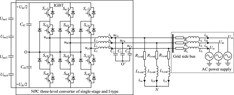
Figure 1. Topology of NPC three-level converter of single-stage and I-type.
In Figure 1, the topology consists of split capacitor, LC filter and A, B, and C phase bridge arms with four IGBTs integrated anti-parallel diodes as well as two clamped continuous-current diodes. The withstand voltage of a single IGBT or diode in each phase bridge arm is Udc/2. Udc represents the voltage at both ports of the DC bus. Because the withstand voltage is halved, the total loss of the topology is also halved, making the topology especially suitable for medium and high voltage distribution system. In terms of A-phase, the on/off sequence of IGBT in the upper/lower bridge arm is that the outer Sa1 and the inner Sa2 are successively turned on or the inner Sa2 and the outer Sa1 are successively turned off. The working principle of the A-phase bridge arm is that when Sa1 and Sa2 are turned on, the output voltage of A-phase of the converter is Udc/2. When Sa2 and Sa3 are turned on, the output voltage of A-phase of the converter is 0. When Sa3 and Sa4 are turned on, the output voltage of A-phase of the converter is −Udc/2.
2.2 GFM control principle for energy storage converter
In this paper, the VSG control is utilized to realize the fast active support control target of frequency and voltage of GFM energy storage converter system, so that PCS can play the role of GFM support of frequency and voltage during disturbance suppression period. The VSG control simulates the mechanical and electromagnetic characteristics of the synchronous generator (SG) through the control strategy, so that the converter presents the inertia support, damping characteristic and frequency as well as voltage response characteristics similar to SG when the load is changed (Me et al., 2023; Yu et al., 2023). The stability and strength of region power grid could be improved.
The principle of GFM-VSG control is as follows. Considering the electromechanical transient response process of SG, the rotor swing equation of SG is appended based on the droop characteristic control method. Then, the system-level control and device-level control are completed by quickly collecting voltage, current and power signals on the converter side. Meanwhile, the dynamic response characteristics of frequency and voltage of SG are successfully simulated. The converter presents the characteristics of frequency synchronization and automatic power sharing, which does not need the phase lock loop (PLL) to complete the control design. And the GFM-VSG control makes the response performance of GFM converter better than that of the grid-following (GFL) converter in the weak grid scenario.
The VSG control adopts active power/frequency control and reactive power/voltage control, hereinafter referred to as P-f control and Q-U control. The P-f control model is designed by simulating the rotor motion process and primary frequency modulation process of SG, which makes the converter have the P-f response characteristic of SG. Figure 2 is the P-f control structure diagram and Eq. 1 is the expression of dynamic response process of P-f control. It can be seen from Figure 2 and Eq. 1 that the active power deviation will change the virtual mechanical power and active power of the converter, alter the phase reference value of the output voltage of the converter. Then, the converter will change the frequency of the network side to achieve the frequency output characteristic similar to SG. The virtual inertia J makes VSG play a role of inertia support in the dynamic response of primary frequency modulation, and the damping coefficient D makes VSG play a role of damping in the process of power oscillation response, which improves the support response ability of frequency and voltage of the converter under disturbance.
where Pref is the reference active power output of the converter, or referred to as virtual mechanical power. P is the actual active power output of the converter. ωref is the reference angular frequency of output voltage on grid side. ω is the actual angular frequency on grid side.
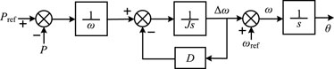
Figure 2. P-f control structure diagram.
The Q-U control model is designed by simulating the excitation regulation process of SG, which makes the converter possess Q-U droop characteristic. Figure 3 is the Q-U control structure diagram and Eq. 2 is the expression of dynamic response process of Q-U control. As can be seen from Figure 3 and Eq. 2, the Q-U control is unsimilar with to SG, which changes the winding induction electromotive force by changing the excitation current. The VSG alters the excitation induction electromotive force E by the reactive power deviation, voltage deviation and integral link, which is utilized to realize the voltage tracking control without static difference.
where Ti is the integral time constant. Qref is the reference reactive power output of the converter. Q is the actual reactive power output of the converter. n is Q-U droop coefficient. Uref is the reference voltage of the converter. U is the actual voltage of the converter.
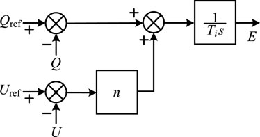
Figure 3. Q-U control structure diagram.
3 Modeling of single-stage NPC energy storage system
Based on Figure 1, in order to facilitate the theoretical modeling of the NPC three-level converter, ignoring the power supply part of the grid side, the mathematical model of the converter in three-phase stationary coordinate system can be deduced through VCR equation and Kirchhoff law of voltage as well as current, as follows.
where uaO, ubO and ucO are the output modulation voltage components of the converter. ia, ib and ic are the output current components of the converter. L1 is the filter inductance. C1 is the filter capacitance. uON is the electrical force difference between mid-point O and neutral point N. uCa, uCb and uCc represent the voltage of capacitor C1 with N as the reference point. uNO′ is the electrical force difference between neutral point N and mid-point O′. iLa, iLb and iLc are the load current components. ZLoad is the load impedance.
If the output modulation voltage uaO, ubO, ucO and load impedance ZLoad are three-phase symmetry, the following condition can be obtained.
By substituting Eq. 4 into Eq. 3, a simplified mathematical model of the converter is obtained, as shown in Eq. 5.
To define the vectors composed of each voltage and current component as shown in Eq. 6, and then Eq. 5 is deduced to obtain Eq. 7.
The Park transformation matrix and the corresponding inverse transformation matrix are defined as P3/2 and P2/3, and the d-axis and q-axis components of voltage and current vectors in two-phase synchronous rotating coordinate system can be obtained as follows.
Based on Eq. 8, the simplified mathematical model of the converter in two-phase synchronous rotating coordinate system can be acquired as follows.
where A is
By multiplying the Eq. 9 with the matrix P3/2, it can be obtained:
Considering P3/2∙P2/3 = I2, where I2 is the second-order identity matrix, the Eq. 10 is simplified again and the Laplace transformation is performed, it can be acquired:
In Eq. 11, udO and uqO are input signals of voltage loop in the simplified mathematical model of the converter. id and iq are the output signals of the voltage loop, or referred to as the input signals of the current loop. uCd and uCq are the output signals of the current loop, and then the schematic diagram of the mathematical model of the converter in two-phase synchronous rotating coordinate system as depicted in Figure 4 can be generated. Based on Figure 4, the design of GFM control strategy of the energy storage converter will be expanded below.
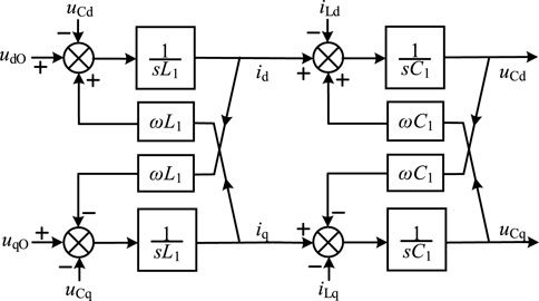
Figure 4. Schematic diagram of the mathematical model of the converter in two-phase synchronous rotating coordinate system.
4 SMC strategy of GFM energy storage converter with fast active support of frequency and voltage
4.1 SMC theory
The traditional current inner loop control of energy storage converter generally adopts PI control, which has the advantage of zero static error tracking, but the response bandwidth is narrow. In the meantime, the control performance will be enormously reduced by the disturbance signal and the control parameter perturbation. The control target can be superiorly tracked by SMC in the cases of large or small disturbance signal interference and control parameter perturbation, which can improve the control response speed and anti-interference ability. Therefore, in this paper, the current inner loop control based on SMC is designed, aiming to improve the response bandwidth of the current inner loop and the fast active support ability of the converter while the system is disturbed.
According to fundamental theory of SMC, the SMC control law design requires to construct the sliding mode surface at first, which is as follows.
where id* and iq* are the d-axis and q-axis reference values of the output current of the converter, respectively.
For chattering problems existing in SMC control, the sliding mode approach law is generally constructed by symbolic function sgn(s), as shown in Eq. 13.
where ε1, γ1, ε2, γ2 are the approach law coefficients greater than zero.
In this paper, the saturation function sat(s) is utilized to improve the approach law Eq. 13 to achieve substantial elimination of chattering in SMC control. The improved approach law is displayed as follows.
where
By substituting Eq. 14 into Eq. 11, the simplified and partial mathematical model of the converters with approach law is obtained.
By substituting Eq. 12 into Eq. 15, the mathematical model of current inner loop controller of the converter based on SMC can be obtained, as shown in Eq. 16.
The schematic diagram of sliding mode controller of current inner loop of the converter replacing the traditional PI controller is shown in Figure 5, where umdO and umqO are the d-axis and q-axis components of the generated voltage modulation wave. The response performance of sliding mode controller of current inner loop will be compared and analyzed in Section 5 of this paper, which is better than the response performance of PI controller.
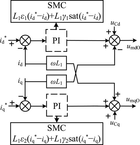
Figure 5. Schematic diagram of sliding mode controller of current inner loop of the converter.
4.2 SMC strategy of GFM energy storage converter with fast active support ability
Based on the VSG control principle in Section 2.2, the VSG controller module of energy storage converter, double loop controller module of voltage and current, power synchronization calculation module, space vector pulse width modulation module (SVPWM) and so on are constructed. Thus, the SMC strategy design of GFM energy storage converter is completed.
The signals of output current iabc and filter capacitance voltage uC of the converter are collected, and the power synchronization calculation module shown in Eq. 17 is designed through Park transformation and equivalent calculation to provide the control input signals for the VSG controller module.
The VSG controller module is made up of P-f control module and Q-U control module. Among that, the P-f control module contains two parts: virtual governor module and virtual frequency modulator module. The virtual governor module makes the converter hold P-f droop external characteristic. The mathematical model and control structure diagram are shown in Eq. 18 and Figure 6, respectively.
where Pm is the mechanical power output of the converter. m is the P-f droop control coefficient.

Figure 6. Control structure diagram of virtual governor module.
Above Eq. 1 and Figure 2 are the mathematical model and control structure diagram of the virtual frequency modulator module. It can be seen that the virtual frequency modulator is derived from the mechanical equation of rotor motion. Considering the no-load torque corresponding to no-load loss in the rotor motion mechanical equation, it can be obtained that VSG output torque is equal to mechanical torque minus electromagnetic torque and no-load torque. And the correlative torque equation is shown in Eq. 19.
where ΔT represents the virtual torque variation of VSG. ΔP is the electromagnetic power variation of VSG. Tm is the mechanical torque of VSG. T is the electromagnetic torque of VSG. Pm is the virtual mechanical power of VSG, which corresponds to the variable Pref in rotor motion Eq. 1 without the function of virtual governor module.
The control structure diagram of the P-f control module can be obtained from Figures 2, 6, as shown in Figure 7.
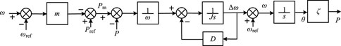
Figure 7. Control structure diagram of P-f control module.
In Figure 7, ζ is the power conversion coefficient. If the parameters J and D in Figure 7 are equal to zero, the P-f control module becomes the P-f droop control. Therefore, P-f control in VSG is regarded as the P-f droop control with inertia support and damping (Gómez-Aleixandre et al., 2023), which can make the converter show the P-f droop control characteristic. Above Eq. 2 and Figure 3 are the mathematical model and control structure diagram of Q-U control module. The module corresponds to the excitation regulator in SG, which outputs the excitation induction electromotive force E. When the reactive power Q outputted by the converter is increased, the actual voltage U will be decreased, thus presenting the Q-U droop control characteristic.
On the basis of Eq. 11 of the mathematical model of the converter in two-phase synchronous rotating coordinate system, the PI controller with no static error control performance is utilized to design a voltage outer loop controller module with decoupling terms, as displayed in Eq. 20, so as to provide the stable reference current input signals to the current inner loop.
where kup and kui are the proportional gain and integral gain of PI controller of voltage outer loop, respectively. uCd* and uCq* are the reference values of d-axis and q-axis of the capacitor voltage, or referred to as the output voltage of the converter respectively, which values are given by the VSG controller after Park transformation. iLd and iLq are respectively the d-axis and q-axis components of load current when the converter is running in islanding mode. When the converter is running in grid-connected mode, iLd and iLq are respectively equal to the corresponding sums of d-axis and q-axis components of load current iLd′ and iLq′ as well as d-axis and q-axis components of grid current isd and isq.
Based on Eqs 16 and20 and Figure 5, the double-loop controller module of voltage and current can be obtained, and the control structure diagram is shown in Figure 8.
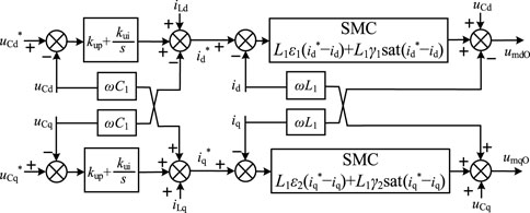
Figure 8. Control structure diagram of double-loop controller module of voltage and current.
In this paper, the SVPWM module based on claw wave is adopted to receive the modulation wave signals, and send the trigger pulse signals to the converter to complete the working mode switching (Yan et al., 2022). Combined with Figure 3, Eq. 17, Figures 7, 8 and SVPWM module, the overall structure diagram of SMC strategy of GFM energy storage converter is obtained, as depicted in Figure 9.
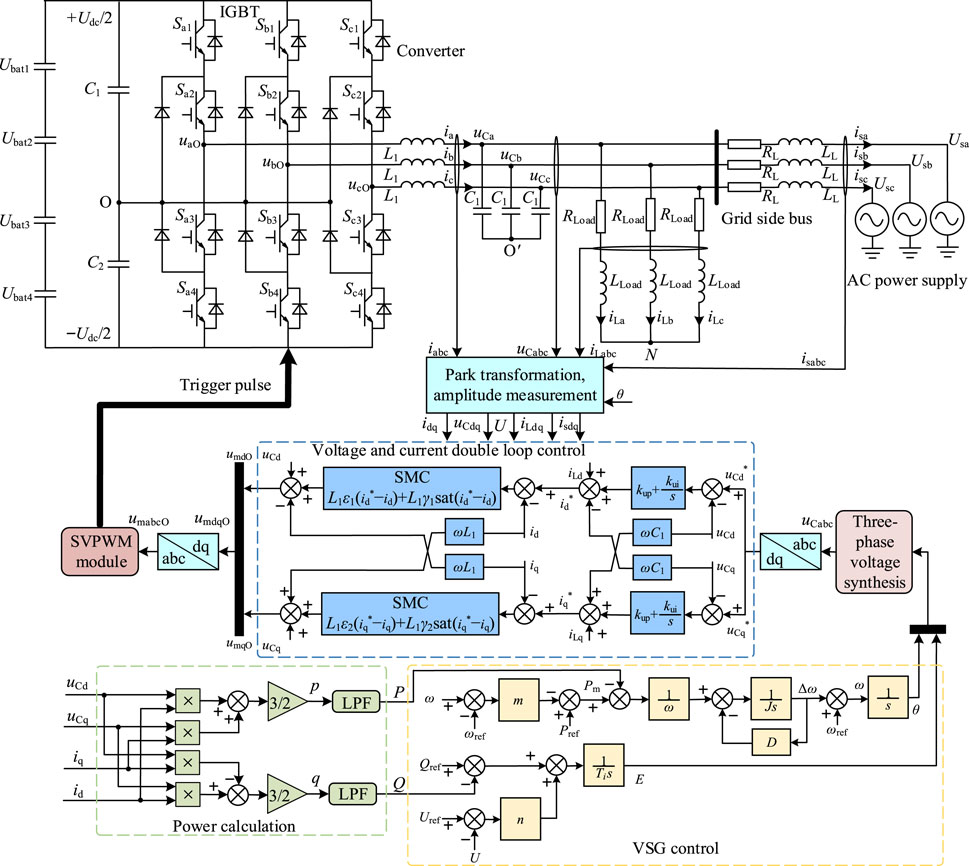
Figure 9. Overall structure diagram of SMC strategy of GFM energy storage converter.
As shown in Figure 9, the control process of the converter to realize the fast active support response of frequency and voltage is as follows. The variable signals are collected by the electrical variable measurement module, and the d/q axis components of each electrical variable are obtained by Park transformation and amplitude measurement module. Then, the active and reactive power signals are acquired by the power calculation module. The signals are sent to the VSG control module, and the reference voltage amplitude and reference phase are generated immediately. After that, the reference value of capacitor voltage is got through three-phase voltage synthesis and Park transformation, and the modulation wave signals are obtained through the double-loop controller of voltage and current with SMC and PI control. Subsequently, the signals are sent to the SVPWM module for modulation to generate the trigger pulse signals, which are emitted to the gates of the corresponding IGBTs for on-off control, and then the working modes of the converter are changed. Finally, the fast active support response target of the converter under disturbance is achieved.
5 Simulation results and analyses
Based on the electromagnetic transient simulation environment of Matlab/Simulink, the SMC system simulation model of GFM energy storage converter is established in this paper, and the corresponding schematic diagram is shown in Figure 10, so as to verify the effectiveness of the proposed SMC strategy of GFM energy storage converter with fast active support ability. The response performance difference of PI control and SMC under frequency/voltage disturbance is compared and analyzed. The fast active support performance of the proposed method is explored.
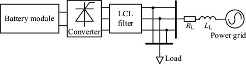
Figure 10. Schematic diagram of SMC system simulation model of GFM energy storage converter.
The system-level configuration parameters and the configuration parameters of GFM energy storage converter system are shown in Tables 1, 2, respectively.
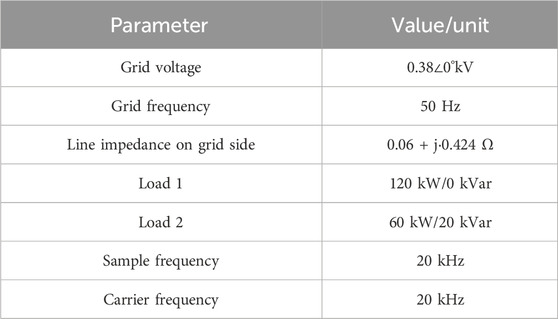
Table 1. System-level configuration parameters.
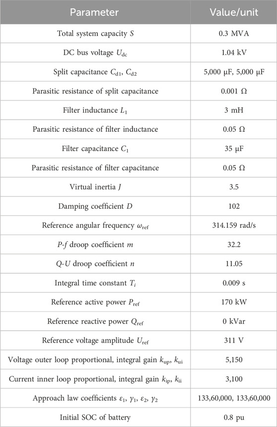
Table 2. Configuration parameters of GFM energy storage converter system.
5.1 Analysis of fast active frequency support performance when power grid fluctuates
When the power grid frequency is fluctuated, the operation condition of fast active frequency support is designed to analyze whether the proposed strategy can achieve the fast active frequency support and suppress the frequency fluctuation of the power grid through P-f control. Meanwhile, the better response performance than that of PI control is observed. To set the system work in grid-connected mode, the initialization is completed by the system within 0–0.05 s, the load 1 is put into operation at 0 s, the frequency of the grid side is dropped by 0.1 Hz at 1 s, lasts for 1 s, and end for 2 s. The related configuration parameters are shown in Tables 1, 2. The response curves of each variable under fast active frequency support condition are showed in Figure 11.
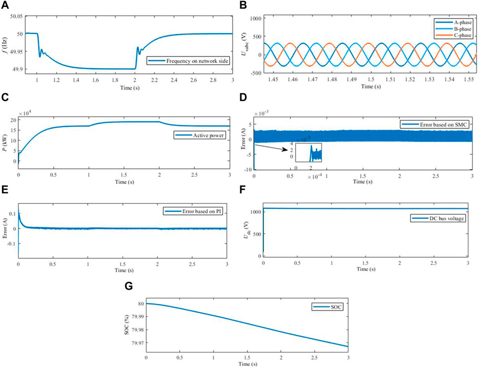
Figure 11. Response curves of each variable under fast active frequency support condition. (A) Frequency in grid side. (B) Voltage in grid side. (C) Active power output of converter. (D) Current inner loop tracking deviation based on SMC. (E) Current inner loop tracking deviation based on PI. (F) DC bus voltage. (G) SOC of battery.
As shown in Figures 11A–C, the frequency of grid side was stabilized at 50 Hz before 1 s, then the frequency began to drop after 1 s. The frequency was stabilized at 49.9 Hz after the dynamic response process of 0.45 s, and then risen after 2 s, finally equal to about 50 Hz. At the period of 1–2 s, the three-phase voltage was balanced and symmetrical, the phase peak value was equal to 311.8 V. After the dynamic response process of 0–0.65 s, the steady state value of active power was about 170 kW. Because the frequency drop was occurred in the power grid after 1 s, the converter began to increase the active power output and quickly played an active frequency support role. Through the transient response process of 0.4 s, the active power was stabilized at 190 kW. After 2 s, the frequency of power grid began to recover, and the active power was recovered to 170 kW at last. It could be seen from Figures 11D, E that, the current inner loop tracking deviations based on SMC and PI within 0–1 s entered the steady state after the transient response processes of 0.25 ms and 0.2 s, respectively, which indicate the d-axis deviations, omitted below. Meanwhile, the maximum steady-state deviations were respectively 0.004 and 0.007 A, indicating that the SMC dynamic response had better rapidness. The steady-state response tracking control was more accurate and the overall performance was better. From the observation of Figures 11F, G, it could be seen that the DC bus voltage began to increase at 0 s and became stable at 1,075 V after 0.62 s. Due to the lack of DC voltage stability control strategy, the voltage existed to the small deviation. At the same time, the DC bus voltage could remain stable during frequency drop response process of 1–2 s. The SOC of the battery had declined in the response process of 0–3 s, and the decline slope of 1–2 s was increased as the active power output was increased. It could be seen that, under the condition of fast active frequency support, the active frequency support target of the power grid could be realized by the proposed method through rapidly increasing the active power, and the SMC had the faster response rate and higher response precision than PI control.
5.2 Analysis of fast active voltage support performance when power grid fluctuates
The operation condition of fast active voltage support when the voltage of the power grid fluctuates is designed to observe whether the proposed strategy can achieve the fast active voltage support under Q-U control and eliminate the influence of voltage fluctuation of the power grid. The operation mode of the system, initialization setup process and load response process are the same as Section 5.1. At 1 s, the voltage amplitude at grid side is dropped by 23 V, lasts for 1 s, and end for 2 s. The response curves of each variable under the condition of fast active voltage support are shown in Figure 12.
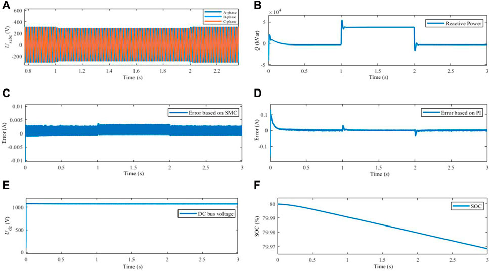
Figure 12. Response curves of each variable under fast active voltage support condition. (A) Voltage in grid side. (B) Reactive power output of converter. (C) Current inner loop tracking deviation based on SMC. (D) Current inner loop tracking deviation based on PI. (E) DC bus voltage. (F) SOC of battery.
As could be seen from Figures 12A, B, the voltage amplitude of grid side was 311.5 V before 1 s, the voltage was reduced within 1–2 s, and the steady state value was 288.5 V. After 2 s, the voltage was risen and finally became 311.5 V. During 0–0.3 s, the reactive power was responded dynamically with a slight overshoot, and the value was eventually stabilized at −3 kVar. A small amount of capacitive reactive power was absorbed by the filter capacitor. The voltage reduction of power grid responded by the converter after 1 s, the reactive power output was augmented, and the goal of rapid active voltage support was realized. Likewise, after the dynamic response process of 0.08 s, the value was approximately 38 kVar. After 2 s, the grid voltage was increased and the reactive power became −3 kVar. As shown in Figures 12C, D, during 0–1 s, the current inner loop tracking deviation based on SMC entered the steady state after 0.2 ms. Simultaneously, the maximum steady-state deviation was 0.0035 A. Within 0–1 s, the current inner loop tracking deviation based on PI turned into the steady state after 0.2 s, and the maximum steady state deviation was 0.01A, which confirmed the faster dynamic response speed and higher steady-state control precision of SMC. The analyses of Figures 12E, F showed that the DC bus voltage was stabilized at 1075 V after the dynamic response process of 0–0.6 s, and then remained unchanged basically, with a small steady-state deviation. Besides, the SOC of the battery had decreased in response to load. In conclusion, the proposed strategy was effective. The reactive power output could be increased by VSG control and SMC when the grid voltage was dropped, which could complete the fast active voltage support task. The current inner loop controller of SMC was characteristic of the superior dynamic and steady-state response performance.
5.3 Analysis of quick power regulation performance when load fluctuates
The operation condition of quick power regulation when the load fluctuates is designed to verify whether the proposed strategy can achieve quick active/reactive power regulation, meet the load demand and exert the quick active support function. The system is connected to the grid, and the initialization process is consistent with Section 5.1. The frequency and voltage of the grid are unchanged all the time. In the meanwhile, Load 1 is put in at 0 s, load 2 is put in at 1 s and removed at 2 s. The response curves of each variable under the condition of quick power regulation are displayed in Figure 13.
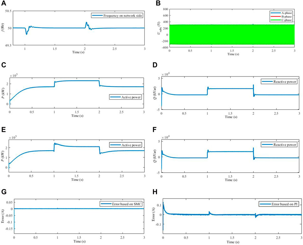
Figure 13. Response curves of each variable under the condition of quick power regulation. (A) Frequency in grid side. (B) Voltage in grid side. (C) Active power output of converter based on SMC. (D) Reactive power output of converter based on SMC. (E) Active power output of converter based on PI. (F) Reactive power output of converter based on PI. (G) Current inner loop tracking deviation based on SMC. (H) Current inner loop tracking deviation based on PI.
It could be seen from Figures 13A, B that, the frequency of grid side was stabilized before 1 s. After 1 and 2 s, the frequency was fluctuated slightly due to load switching, and then recovered to stability. The voltage peak of grid side was equal to 311.8 V in 0–1 s and 2–3 s, and was decreased to 305 V in 1–2 s due to the input of load 2. The analyses of Figures 13C, D showed that the active power and reactive power were stabilized at 170 kW and −3 kVar after 0.65 and 0.35 s, respectively. In this paper, the values of virtual inertia and damping coefficient were large, resulting in no overshoot in the active power response and a small overshoot in the reactive power response. During 1–2 s, after the dynamic response processes of 0.26 and 0.08 s, the active power and reactive power were stabilized at 230 kW and 9.4 kVar, respectively. After 2 s, load 2 was cut off, the active power and reactive power were recovered to 170 kW and 17 kVar. As a result, the speed of power regulation was faster, which could satisfy the demand of load electricity and realize the fast active support. The analyses of Figures 13E, F showed that, based on PI control, the active power and reactive power were stabilized at 170 kW and −3 kVar after 0.8 and 0.42 s, respectively. Simultaneously, there was a slight overshooting of reactive power response. After 1 s, though the dynamic response process of 0.42 and 0.3 s, the active power and reactive power were stabilized at 229.5 kW and 9.35 kVar, respectively. After 2 s, load 2 was cut off, the active power and reactive power were recovered to 170 kW and −3 kVar. As a result, the power adjustment rate was about 0.2 s slower than SMC, and the dynamic response performance was not as good as SMC. As could be known from Figures 13G, H, the times required to enter the steady state of the current inner loop tracking deviations based on SMC and PI were about 0.21 ms and 0.22 s, respectively. The current inner loop tracking deviation based on PI had response fluctuation in the load switching process at 1 s and 2 s, and entered steady state after the transient process of about 0.17 s. The superior transient response speed and steady-state tracking ability of SMC were verified. It could be seen that the proposed strategy could quickly adjust the active power output and reactive power output when the load was disturbed. In the meanwhile, the fundamental stability of frequency and voltage of grid side was maintained and the active support control goal was realized quickly.
6 Conclusion
In order to reduce the influence of renewable energy generation on the stability regulation of frequency and voltage of active distribution network and improve the active support ability of the converter, the topology and GFM principle of GFM energy storage converter system were studied in this paper. The lithium iron phosphate battery was selected to undertake the energy storage task. Meanwhile, the traditional equivalent circuit model of lithium iron phosphate battery was improved. The equivalent models of the converter under two-phase synchronous rotating coordinate system were established. Based on SMC, the current inner loop control of the converter was improved, and the SMC strategy of GFM energy storage converter with fast active support of frequency and voltage was proposed. Through simulation verifications and comparative analyses, the following conclusions were drawn.
The response speed of current inner loop control based on SMC was about 0.2 s faster than that based on PI, the maximum steady-state deviation was about 0.004 A, and the maximum response time of SMC current inner loop entering steady-state was no more than 0.25 ms. After the improvement, the response speed was greatly increased and could meet the requirements of power grid regulation. The delay effect when VSG control simulates SG for inertia support, damping control and voltage outer loop control could be improved.
The proposed SMC strategy of GFM energy storage converter could provide the inertia support and damping control to the system through VSG control and SMC current inner loop control under operation conditions of frequency, voltage and load fluctuations, which could play a fast active support role to improve the dynamic control performance and steady-state tracking capability of the converter. At the same time, the stable operation performance of active distribution network was enhanced and the support strength of power grid was increased.
Data availability statement
The original contributions presented in the study are included in the article/Supplementary Material, further inquiries can be directed to the corresponding author.
Author contributions
CH: Conceptualization, Writing–original draft, Writing–review and editing. HC: Funding acquisition, Writing–review and editing. AT: Investigation, Writing–review and editing.
Funding
The author(s) declare that financial support was received for the research, authorship, and/or publication of this article. This research was funded by Research on System Construction and Key Technology of Relay Protection Active Defense for Active Distribution Network, grant number B311HZ23000P.
Acknowledgments
The authors wish to thank the respected editors and reviewers for contributing their precious time, pertinent and constructive suggestions, and suggestions that have helped advance the quality of the study. In addition, the authors would like to express the gratitude to Wei Ma and Dongran Liu from State Grid Hangzhou Power Supply Company, Hangzhou 310000, China, for their contributions to Writing–Original Draft Preparation and Writing–Review and Editing.
Conflict of interest
Author CH was employed by State Grid Hangzhou Power Supply Company.
The remaining authors declare that the research was conducted in the absence of any commercial or financial relationships that could be construed as a potential conflict of interest.
Publisher’s note
All claims expressed in this article are solely those of the authors and do not necessarily represent those of their affiliated organizations, or those of the publisher, the editors and the reviewers. Any product that may be evaluated in this article, or claim that may be made by its manufacturer, is not guaranteed or endorsed by the publisher.
References
Babu, Y. N., and Padhy, N. P. (2023). An approach to improve harmonic attenuation and stability performance in multi-parallel inverter system. IEEE Trans. Power Deliv. 38, 3634–3646. doi:10.1109/TPWRD.2023.3287761
Bansal, Y., Sodhi, R., Chakrabarti, S., and Sharma, A. (2023). A novel two-stage partitioning based reconfiguration method for active distribution networks. IEEE Trans. Power Deliv. 38 (6), 4004–4016. doi:10.1109/TPWRD.2023.3298470
Busada, C., Jorge, S. G., and Solsona, J. A. (2024). Current-controlled synchronverter: a grid fault tolerant grid forming inverter. IEEE Trans. Ind. Electron. 71, 3233–3241. doi:10.1109/TIE.2023.3277109
Cai, H., Chen, M., Hu, C., and Ren, S. (2023). Study of charging current ripple suppression for battery energy storage converter under distorted grid voltages. IEEE Trans. Power Electron. 38, 7993–7999. doi:10.1109/TPEL.2023.3262946
Chakraborty, S., Patel, S., Saraswat, G., Maqsood, A., and Salapaka, M. V. (2024). Seamless transition of critical infrastructures using droop-controlled grid-forming inverters. IEEE Trans. Ind. Electron. 71, 1535–1546. doi:10.1109/TIE.2023.3253946
Chamarthi, P. K., Moursi, M. S. E., Khadkikar, V., Hosani, K. H. A., Al-Durra, A., and EL-Fouly, T. H. M. (2022). A single stage doubly grounded transformerless inverter topology with buck-boost voltage capability for grid connected PV systems. IEEE Trans. Power Deliv. 37, 5044–5058. doi:10.1109/TPWRD.2022.3166506
Conte, F., D’Agostino, F., Gabriele, B., Schiapparelli, G. P., and Silvestro, F. (2023). Fault detection and localization in active distribution networks using optimally placed phasor measurements units. IEEE Trans. Power Syst. 38 (1), 714–727. doi:10.1109/TPWRS.2022.3165685
Fan, B., Li, Q., Wang, W., Yao, G., Ma, H., Zeng, X., et al. (2022). A novel droop control strategy of reactive power sharing based on adaptive virtual impedance in microgrids. IEEE Trans. Ind. Electron. 69, 11335–11347. doi:10.1109/TIE.2021.3123660
Figueroa, F., Lizana Fuentes, R., Goetz, S. M., and Rivera, S. (2023). Operation of a hybrid energy storage system based on a cascaded multi-output multilevel converter with a carrier-based modulation scheme. Energies 16, 7150. doi:10.3390/en16207150
Gerini, F., Zuo, Y., Gupta, R., Zecchino, A., Yuan, Z., Vagnoni, E., et al. (2022). Optimal grid-forming control of battery energy storage systems providing multiple services: modeling and experimental validation. Electr. Power Syst. Res. 212, 108567. doi:10.1016/j.epsr.2022.108567
Ghosh, R., Tummuru, N. R., and Rajpurohit, B. S. (2023). A new virtual oscillator-based grid-forming controller with decoupled control over individual phases and improved performance of unbalanced fault ride-through. IEEE Trans. Ind. Electron. 70, 12465–12474. doi:10.1109/TIE.2023.3236069
Gómez-Aleixandre, C., Á, N.-R., Blanco, C., Villa, G., Suárez, A., and García, P. (2023). Analysis of a complex-valued droop method for complete steady-state frequency compensation using dq-decomposition. IEEE Trans. Ind. Appl. 59, 7657–7668. doi:10.1109/TIA.2023.3300259
Guan, M. (2022). Scheduled power control and autonomous energy control of grid-connected energy storage system (ESS) with virtual synchronous generator and primary frequency regulation capabilities. IEEE Trans. Power Syst. 37, 942–954. doi:10.1109/TPWRS.2021.3105940
Hamad, B., Al-Durra, A., El-Fouly, T. H. M., and Zeineldin, H. H. (2023). Economically optimal and stability preserving hybrid droop control for autonomous microgrids. IEEE Trans. Power Syst. 38, 934–947. doi:10.1109/TPWRS.2022.3169801
Leon, A. E., Jorge, S. G., Busada, C. A., and Solsona, J. A. (2024). Model-matching control for low switching frequency converters unifying different performance requirements. IEEE Trans. Ind. Electron. 71, 1125–1134. doi:10.1109/TIE.2023.3253929
Liang, G., Rodriguez, E., Farivar, G. G., Nunes, E., Konstantinou, G., Townsend, C. D., et al. (2024). Model predictive control for intersubmodule state-of-charge balancing in cascaded H-bridge converter-based battery energy storage systems. IEEE Trans. Ind. Electron. 71, 5777–5786. doi:10.1109/TIE.2023.3290249
Long, B., Zhu, S., Rodriguez, J., Guerrero, J. M., and Chong, K. T. (2023). Enhancement of power decoupling for virtual synchronous generator: a virtual inductor and virtual capacitor approach. IEEE Trans. Ind. Electron. 70, 6830–6843. doi:10.1109/TIE.2022.3206701
Lyu, X., and Groß, D. (2024). Grid forming fast frequency response for PMSG-based wind turbines. IEEE Trans. Sustain. Energy 15, 23–38. doi:10.1109/TSTE.2023.3263858
Me, S. P., Ravanji, M. H., Leonardi, B., Ramasubramanian, D., Ma, J., Zabihi, S., et al. (2023). Transient stability analysis of virtual synchronous generator equipped with quadrature-prioritized current limiter. IEEE Transa. Power Electron. 38, 10547–10553. doi:10.1109/TPEL.2023.3278835
Park, J.-Y., and Chang, J.-W. (2024). Novel autonomous control of grid-forming DGs to realize 100% renewable energy grids. IEEE Trans. Smart Grid 15, 2866–2880. doi:10.1109/TSG.2023.3322608
Reyes, E., Sarasiri, N., Pena, R., Riedemann, J., Andrade, I., Blasco-Gimenez, R., et al. (2022). DC current harmonics reduction in multi-inverter topology. IEEE Trans. Power Deliv. 37, 4489–4492. doi:10.1109/TPWRD.2022.3184187
Shi, Z., Ruan, J., Hong, Y., Li, M., and Liu, D. (2023). Dual-module VSG control strategy under unbalanced voltage conditions. J. Power Electron. 23, 923–934. doi:10.1007/s43236-022-00587-8
Sun, C., Ali, S. Q., Joos, G., and Bouffard, F. (2022). Design of hybrid-storage-based virtual synchronous machine with energy recovery control considering energy consumed in inertial and damping support. IEEE Trans. Power Electron. 37, 2648–2666. doi:10.1109/TPEL.2021.3111482
Tang, A., Ma, L., Qiu, P., Song, J., Chen, Q., Guan, M., et al. (2023). Research on the harmonic currents rates for the exchanged energy of unified distributed power flow controller. IET Generation, Transm. Distribution 17, 530–538. doi:10.1049/gtd2.12741
Tang, A., Zhou, W., Song, J., Qiu, P., Chen, Q., Zhai, X., et al. (2022). Optimal output power coordinated control strategy of distributed power flow controller. Int. J. Electr. Power Energy Syst. 140, 108075. doi:10.1016/j.ijepes.2022.108075
Tian, W., Liao, S., Wang, L., Zhou, X., and Xu, Q. (2022). New adaptive broadband full-bridge converter impedance matching network for giant magnetostrictive transducer. IEEE Trans. Power Electron. 37, 7652–7662. doi:10.1109/TPEL.2022.3145654
Ungerland, J., Poshiya, N., Biener, W., and Lens, H. (2023). A voltage sensitivity based equivalent for active distribution networks containing grid forming converters. IEEE Trans. Smart Grid 14 (4), 2825–2836. doi:10.1109/TSG.2022.3221874
Wang, L., Li, T., Cheng, Z., Hu, X., Li, Z., Liu, Z., et al. (2023). A unified droop control of AC microgrids under different line impedances: revisiting droop control and virtual impedance method. Front. Energy Res. 11, 1190833. doi:10.3389/fenrg.2023.1190833
Yan, H., Yang, J., and Zeng, F. (2022). Three-phase current reconstruction for PMSM drive with modified twelve sector space vector pulse width modulation. IEEE Trans. Power Electron. 37, 15209–15220. doi:10.1109/TPEL.2022.3188425
Yu, Y., Guan, Y., Kang, W., Chaudhary, S. K., Vasquez, J. C., and Guerrero, J. M. (2023). Fractional-order virtual synchronous generator. IEEE Trans. Power Electron. 38, 6874–6879. doi:10.1109/TPEL.2023.3244670
Zhang, H., Xiang, W., and Wen, J. (2024b). Dual grid-forming control with energy regulation capability of MMC-HVDC system integrating offshore wind farms and weak grids. IEEE Trans. Power Syst. 39, 261–272. doi:10.1109/TPWRS.2023.3244807
Zhang, H., Xiong, L., Gao, Z., Yu, S., and Zhang, X. (2024a). Power matching based current limitation method for grid forming converter under large disturbances. Int. J. Electr. Power Energy Syst. 157, 109841. doi:10.1016/j.ijepes.2024.109841
Zhao, F., Shuai, Z., Huang, W., Shen, Y., Shen, Z. J., and Shen, C. (2022). A unified model of voltage-controlled inverter for transient angle stability analysis. IEEE Trans. Power Deliv. 37, 2275–2288. doi:10.1109/TPWRD.2021.3109007
Zhao, F., Wang, X., Zhou, Z., Sun, Y., Harnefors, L., and Zhu, T. (2023a). Robust grid-forming control with active susceptance. IEEE Trans. Power Electron. 38, 2872–2877. doi:10.1109/TPEL.2022.3223511
Zhao, J., Du, S., Dong, Y., Su, J., and Xia, Y. (2023b). A bidirectional loss allocation method for active distributed network based on virtual contribution theory. Int. J. Electr. Power Energy Syst. 153, 109349. doi:10.1016/j.ijepes.2023.109349
Zhou, D., Wang, J., Li, Y., Zou, J., and Sun, K. (2022). Model predictive power control of grid-connected quasi single-stage converters for high-efficiency low-voltage ESS integration. IEEE Trans. Ind. Electron. 69, 1124–1134. doi:10.1109/TIE.2021.3059539
Keywords: sliding mode control, grid forming control, energy storage system, control of frequency and voltage, battery modeling
Citation: Hu C, Chen H and Tang A (2024) Sliding mode control strategy of grid-forming energy storage converter with fast active support of frequency and voltage. Front. Energy Res. 12:1416591. doi: 10.3389/fenrg.2024.1416591
Received: 12 April 2024; Accepted: 05 July 2024;
Published: 24 July 2024.
Edited by:
Di Wu, North China Electric Power University, ChinaReviewed by:
Zilin Li, Hong Kong Polytechnic University, Hong Kong SAR, ChinaDazhong Ma, Northeastern University, China
Copyright © 2024 Hu, Chen and Tang. This is an open-access article distributed under the terms of the Creative Commons Attribution License (CC BY). The use, distribution or reproduction in other forums is permitted, provided the original author(s) and the copyright owner(s) are credited and that the original publication in this journal is cited, in accordance with accepted academic practice. No use, distribution or reproduction is permitted which does not comply with these terms.
*Correspondence: Aihong Tang, YWlob25ndGFuZzIwMjQwNEAxNjMuY29t