 Huanle Zhai
 Wei Li
 Xiaomeng Chu1
- 1Aviation Engineering Institute, Jiangsu Aviation Technical College, Zhenjiang, China
- 2China National Research Center of Pumps, Jiangsu University, Zhenjiang, China
- 3The Third Pipeline Branch Office, Beijing Drainage Group, Beijing, China
The hydrogen circulation pump (HCP), a device for recovering unconsumed hydrogen gas in fuel cell systems to improve efficiency, is an important equipment in fuel cell systems. Efficient calculation of the output flow rate of the HCP is crucial for accelerating the product development process, but there is a lack of an effective calculation formula for the working clearance leakage. In this paper, a series of HCP models with different working clearances are established and calculated using an overlapping grid simulation method, verifying that the traditional Roots blower leakage flow formula is feasible for HCP, although the maximum calculation error reaches 10.71%. Further study the pressure distribution law inside the HCP chamber, and revise the traditional calculation formula accordingly, so that the average calculation error of the series models is reduced from 5.75% to 3.82%, and the maximum error is also reduced to 7.73%. Compared with the prototype test data, though the flow values obtained from the two calculation formulas are slightly higher, the calculation error of the correction formula is relatively smaller. The research results indicate that the correction formula can more accurately predict the flow rate of HCP and has important application value.
1 Introduction
Nowadays, fuel cells are considered a renewable energy source and have been used as power sources for many mechanical devices because they are environmentally friendly, reliable and efficient (Chen et al., 2023a; Chen et al., 2023b; Zuo et al., 2024a; Zuo et al., 2024b; Chen et al., 2024). The HCP is an important equipment in fuel cell systems. Its main function is to recover unconsumed hydrogen from the anode of the fuel cell stack and transport it back to the inlet of the stack to improve hydrogen utilization efficiency, while optimizing the lifespan and performance of the fuel cell stack (Liu et al., 2020a; Wilhelm et al., 2020), as shown in Figure 1. The main structural forms of HCP include claw type and Roots type. Claw type pump is a rotary displacement pump with built-in compression, its main advantage is its compact structure (Wang et al., 2015; Gu et al., 2020; Gu et al., 2021), the disadvantages are that the output pressure and flow rate fluctuate greatly, and the stability is poor (Wang and Ma, 2019). Roots type pump is a rotary displacement rotor pump with a pair of meshing rotors containing slots inside, which transport gas through the rotation of the rotors. Its characteristics are simple structure, high reliability, low cost, and large adjustable flow range (Liu et al., 2018; Zhou et al., 2022; Wu et al., 2023). Roots type HCP is the mainstream structural form of current market applications and also the research object of this article.
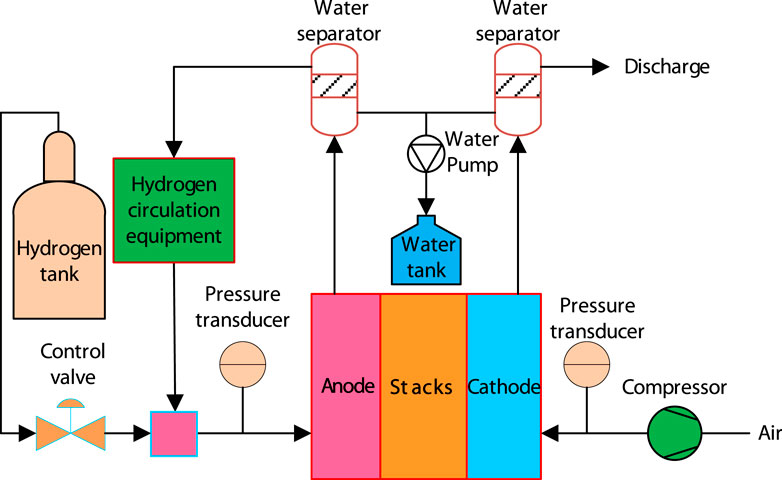
Figure 1. Hydrogen supply system for fuel cells.
In addition to focusing on rotor profile design (Jia et al., 2009; Chiu-Fan, 2015; Liu et al., 2020b; Lin et al., 2021; Huanle et al., 2022), some scholars have also conducted research on flow characteristic simulation calculation methods for Roots type HCP (Yibin et al., 2020; Huanle et al., 2023; Shuo et al., 2023; Xing et al., 2023). They find that the internal leakage of rotor motion clearance is an important factor in reducing pump fluid performance (Joshi et al., 2006; Zhu et al., 2022; Peng et al., 2023). When the working clearance is smaller, the leakage loss inside the pump is less, and the volumetric efficiency is higher, but the machining and assembly accuracy requirements for the pump chamber and rotor are higher, resulting in higher manufacturing costs. Xing et al. (2020) demonstrated through experimental methods that the main factor affecting the flow rate of a Roots pump with helical rotors is pressure difference, while the main factor affecting volumetric efficiency and isentropic efficiency is clearance leakage. Chen et al. (2017) studied three rotor pump models with different radial clearances and found that the volumetric efficiency and mass flow rate of the rotor pump decreased with the increase of the working clearance. Among them, the radial clearance leakage flow rate between the rotors is higher than that between the rotor and the pump casing. Xiang and Lin (2022) analyzed the reasons for the decrease in volumetric efficiency of HCP caused by the increase in radial clearance and found that as the radial clearance increased, more high-pressure gas leaked from the exhaust chamber to the intake chamber. This reduces the overall pressure difference between the intake and exhaust chambers, leading to an increase in leakage velocity at the clearance and a noticeable backflow phenomenon. It results in a decrease in the actual exhaust flow rate of the Roots pump and a decrease in volumetric efficiency. Qin et al. (2022) studied the effect of radial clearance on the flow characteristics of rotor pumps. When the radial clearance increased from 0.1 mm to 0.3 mm, the high-speed flow area in the pump chamber expanded, the vortex intensity increased, and the flow stability decreased. Rao and Zhong (2021) analyzed the influence of axial clearance on the performance of cycloidal rotor pumps. When the speed is kept constant, the volumetric efficiency of cycloidal rotor pumps shows a significant downward trend with the increase of axial clearance, but the amplitude of flow pulsation does not change significantly; When the axial clearance is kept constant, the volumetric efficiency of the cycloidal rotor pump shows a significant increasing trend with the increase of speed. Zhengxian et al. (2007) provided a formula for calculating the internal leakage of a high-pressure Roots blower and compared the calculated results with the experimental values of the blower. The results showed good agreement between the two.
Currently, there is relatively little research on the clearance leakage characteristics of HCP. Most of the research is focused on rotor pumps with similar structures in other industries and mainly focuses on analyzing the impact of clearances on the flow characteristics of Roots pumps. There is little research on the calculation formula for the leakage flow rate of HCP. Although some scholars have studied the calculation formula for the leakage flow rate of Roots blower, due to the significant difference between the research object and the working environment, their research conclusions cannot be directly applied to HCPs. Therefore, this article will analyze and compare the traditional Roots blower leakage flow calculation formula based on the simulation results of the HCP, and propose further correction methods to provide theoretical guidance for the reasonable design of the clearance size of the HCP.
2 Theoretical calculation of leakage flow rate during work clearances
2.1 Traditional formula for calculating internal leakage
The working clearance of the HCP includes the radial clearance between the rotors, the radial clearance between the rotor and the pump casing, the axial clearance between the rotor and the upper cover plate, and the axial clearance between the rotor and the lower cover plate. Usually, the numerical design of the two radial clearances is the same, denoted as δ1, and the numerical design of the two axial clearances is the same, denoted as δ2. Next, according to the traditional Roots blower internal leakage calculation formula, the output flow rate Q of the HCP will be calculated.
(1) Theoretical flow calculation formula for HCP is Eq. 1:
Where,
(2) Calculation formula of radial clearance leakage is Eq. 2:
Where,
(3) The formula for calculating the axial clearance leakage is Eq. 3:
Where,
(4) Calculation formula for output flow of HCP is Eq. 4:
2.2 Output flow calculation of HCP
The design parameters such as the length, width, and height of the pump housing cavity remain unchanged, and different HCP models are designed by adjusting the radial and axial clearances. For ease of expression, the model number is denoted as HCPXX-YY, where XX represents the radial clearance value and YY represents the axial clearance value. For example, when the radial clearance δ1 is 0.10 mm and the axial clearance δ2 is 0.14 mm, the model can be expressed as HCP10-14.
Design four HCP models with different rotor radial clearances to study the reliability and correction method of the traditional calculation formula for radial clearance leakage flow rate. The four models are HCP10-0, HCP14-0, HCP18-0, and HCP22-0, with the radial clearance δ1 is 0.10 mm, 0.14 mm, 0.18 mm, and 0.22 mm in sequence, and all axial clearances δ2 are 0. Redesign four models HCP10-10, HCP10-14, HCP10-18, and HCP10-22 to study the reliability and correction method of the traditional calculation formula for axial clearance leakage flow rate, with all radial clearance δ1 are 0.10 mm, with axial clearance δ2 is 0.10 mm, 0.14 mm, 0.18 mm, and 0.22 mm in sequence.
According to the design parameters shown in Table 1, the theoretical flow Q0 of the series of HCP models can be calculated, Q0 = 75.1 Nm3/h. The output flow QC can be calculated as the medium is hydrogen, the inlet and outlet pressure difference is 10 kPa and the rotational speed is 6000 r/min, as shown in Table 2.
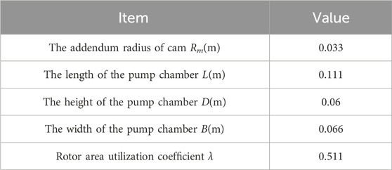
Table 1. Design parameters of the HCP.
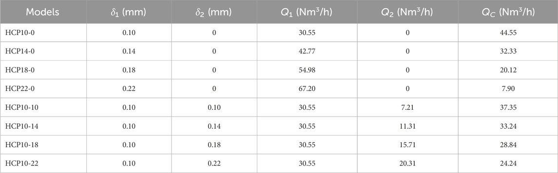
Table 2. Output flow calculation for a series of HCP models.
According to the calculation results, it can be found that the leakage flow of the radial clearance is higher than that of the axial clearance with the same size, and with the increase of the clearance size, the leakage flow difference between the radial and axial clearance gradually increases.
3 Analysis and comparison of leakage flow in working clearance
3.1 Meshing and simulation calculation
The model of HCP is composed of pump body, left and right rotors, inlet, outlet, upper and lower axial clearance. To reduce the influence of pressure loss on clearance leakage characteristics, the inlet and outlet use large square pipes. Establish hexahedral grids for the HCP model and use the overlapping grid method of STAR-CCM software for turbulence calculation, as shown in Figure 2. The number of overlapping grid layers at the clearance between the pump cavity and the rotor is 5, and between the two rotors is 6, which meets the requirements of the minimum overlapping grid layers of 4 and has high reliability. The velocity vector streamline at a certain state after turbulence calculation of HCP is shown in Figure 3, and the reflux streamline at the clearance can be seen clearly.
Figure 2. Grid model of the HCP.
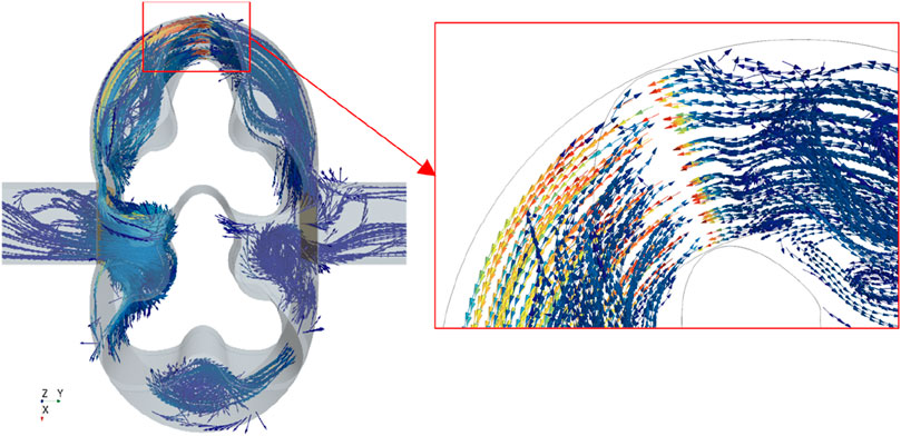
Figure 3. Velocity vector streamlines of the HCP model.
3.2 Analysis and comparison of radial clearance leakage flow
Figure 4 shows the comparison between the simulated average flow values and the theoretically calculated flow for the HCP models with different radial clearances. Define the error between the theoretically calculated value and the simulated value using the simulated result as the standard value. The simulated average flow value of HCP10-0 model is 45.0 Nm3/h, with an error of 0.99% compared to the theoretically calculated value; the HCP14-0 model is 31.0 Nm3/h, with an error of 4.30%; the HCP18-0 model is 22.4 Nm3/h, with an error of 10.20%; the HCP22-0 model is 8.8 Nm3/h, with an error of 10.27%. The results show that the output flow of the HCP decreases linearly with the proportional increase of the radial clearance, and the theoretically calculated results are generally close to the simulation results, indicating that the traditional formula for calculating radial clearance leakage flow rate is relatively reliable. However, as the increase of radial clearance, the calculation error tends to enlarge, indicating that the calculation formula needs further correction.
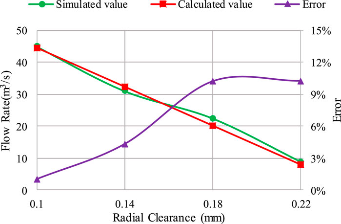
Figure 4. Comparison between the theoretically calculated flow and the simulated flow of HCP models with different radial clearances.
3.3 Analysis and comparison of axial clearance leakage flow
Figure 5 shows the comparison between the simulated average flow values and the theoretically calculated flow for the HCP models with different axial clearances. The simulated average flow value of HCP10-10 model is 39.25 Nm3/h, with an error of 4.85% compared to the theoretically calculated value; the HCP10-14 model is 32.41 Nm3/h, with an error of 2.56%; the HCP10-18 model is 22.40 Nm3/h, with an error of 2.13%; the HCP10-22 model is 21.90 Nm3/h, with an error of 10.71%. The results show that the output flow of the HCP decreases linearly with the proportional increase of the axial clearance, but the decreasing rate is smaller than that of the radial clearance with the same size, indicating that the leakage flow of the axial clearance is lower than that of the radial clearance with the same size, which is consistent with the theoretically calculated flow change trend. The theoretically calculated results are generally close to the simulation results, indicating that the traditional formula for calculating axial clearance leakage flow is relatively reliable. However, there are also large calculation errors in individual models, which need to be further corrected.
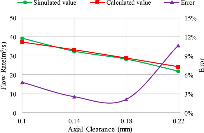
Figure 5. Comparison between the theoretically calculated flow and the simulated flow of HCP models with different axial clearances.
4 Correction and verification of leakage flow calculation formula
4.1 Correction of leakage flow calculation formula
The maximum error of the output flow of the four models with different radial clearances between the calculated value and the simulated value is 10.27%, and the maximum error of the output flow of the four models with different axial clearances is 10.71%, which shows that the traditional calculation formula still has shortcomings and needs to be further improved.
Firstly, the pressure difference in the traditional leakage calculation formula refers to the pressure difference between the intake and exhaust ports, but the actual pressure difference that affects the leakage flow of the pump cavity clearance should be the pressure difference between the high-pressure and low-pressure areas of the pump cavity. The two pressure differences are not the same and are mainly affected by the size of the inlet and outlet pipelines. When the inlet and outlet pipe size is large, the pressure loss at the connections between the inlet pipe and the low-pressure pump cavity area, and between the high-pressure pump cavity area and the outlet pipe are relatively small. According to the Bernoulli equation, the pressure difference between the low-pressure area and the high-pressure area in the pump cavity will be slightly lower than that between the inlet and outlet. When the inlet and outlet pipe size is small, the pressure loss is relatively large, and the pressure difference between the low-pressure area and the high-pressure area is significantly higher than that between the inlet and outlet. Therefore, it is necessary to add the differential pressure coefficient in the radial and axial clearance leakage formulas. Its value is affected by the size of inlet and outlet pipes, which can be determined through simulation or experimental methods.
Secondly, in the traditional formula for calculating axial clearance leakage,
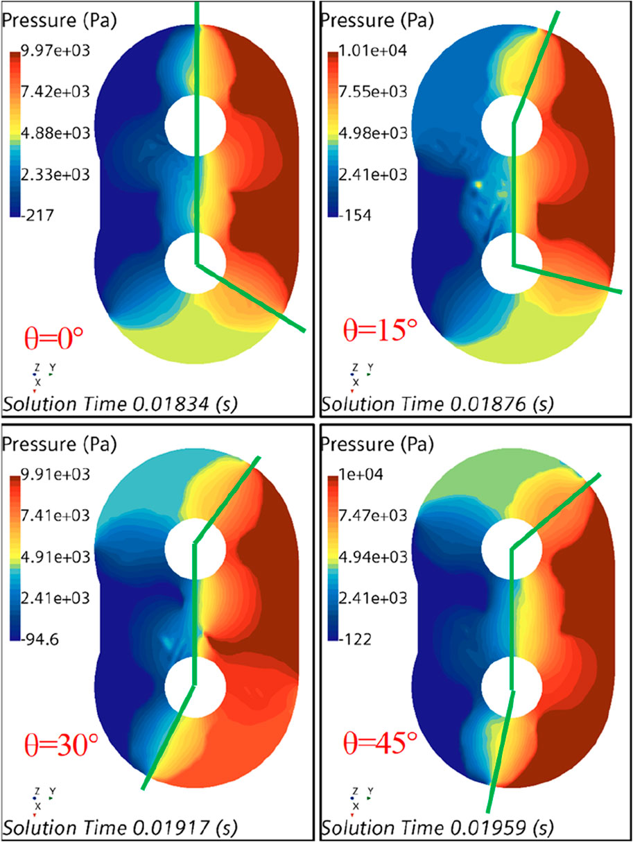
Figure 6. Pressure field distribution at the axial clearance of the HCP model.
According to the above analysis, Eqs 2, 3 are revised as Eqs 5, 6:
Where,
4.2 Verification of leakage flow correction formula
On the one hand, the modified formula is verified based on the simulation data of the series HCP models. Figure 7 shows the pressure distribution in a fluctuation period inside the pump chamber. It can be obtained that the average pressure difference between the high-pressure area and the low-pressure area is 9.8 kPa, which is slightly lower than the pressure difference of 10 kPa between the inlet pipe and the outlet pipe. Therefore, the pressure difference coefficient
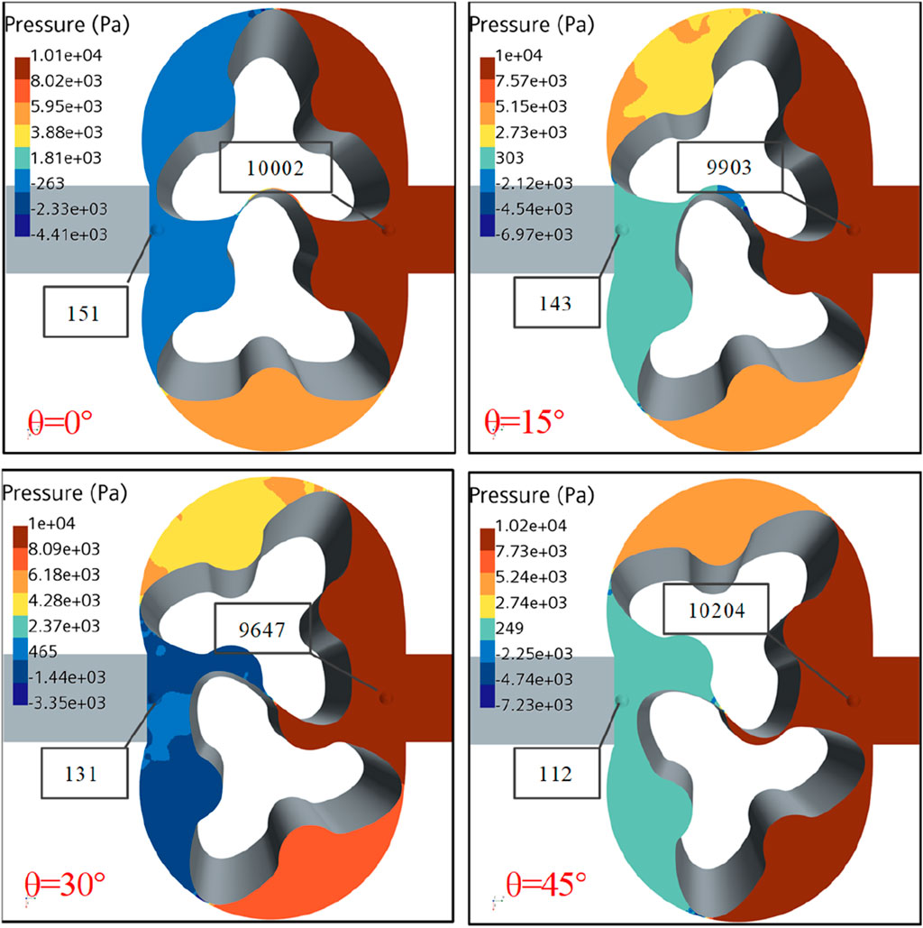
Figure 7. Pressure field distribution in the high-pressure and low-pressure areas inside the pump chamber.
The calculated flow rates for HCP10-0, HCP14-0, HCP18-0, HCP22-0, HCP10-10, HCP10-14, HCP10-18 and HCP10-22 are 44.86 Nm3/h, 32.76 Nm3/h, 20.67 Nm3/h, 8.57 Nm3/h, 37.80 Nm3/h, 33.43 Nm3/h, 28.55 Nm3/h and 23.28 Nm3/h, respectively. Comparing the calculation error of the traditional clearance leakage flow formula and the modified clearance leakage flow formula, the results are shown in Figure 8. It can be seen that the calculation error of the correction formula is better than that of the traditional formula, and the average calculation error of the 8 models decreased from 5.75% to 3.82%.
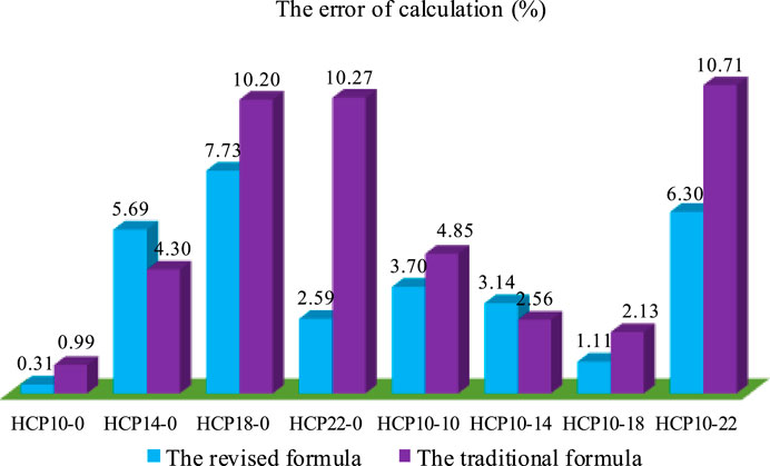
Figure 8. Comparison between the correction formula and the traditional formula.
On the other hand, the prototype is manufactured for testing, as shown in Figure 9, and the correction formula is verified based on the prototype test data. The radial and axial clearance of the prototype are both 0.1 mm. The rotor profile is consistent with the HCP10-10 model designed previously. The height of the pump chamber is adjusted from 60 mm to 40 mm, and the inlet and outlet pipes transition from square to circular. Due to the difficulty in measuring the pressure difference between the low-pressure and high-pressure areas in the pump chamber, the simulation method is used to obtain the pressure curves of point A and point B while the pressure difference between the inlet and the outlet is set to 20 kPa, resulting in a pressure difference of 21.05 kPa, as shown in Figure 10, and then determine the value of differential pressure coefficient
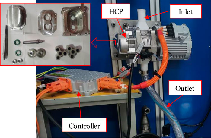
Figure 9. Prototype manufacturing and testing.
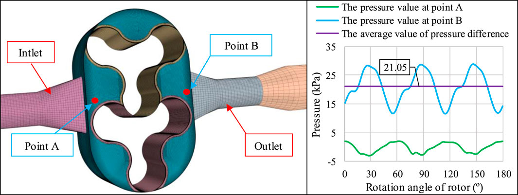
Figure 10. Pressure curve calculation of internal points of prototype model.
The air medium is used to test the prototype. The inlet pipe is in direct contact with the air, with an inlet pressure of 0 kPa. Adjust the valve opening on the outlet pipe to 10%, set the motor speed to 2,000 r/min, 2,500 r/min, 3,000 r/min and 3,500 r/min respectively, and the corresponding outlet flow (outlet pressure) is 10.38 Nm3/h (6.2 kPa), 12.48 Nm3/h (8 kPa), 15.12 Nm3/h (12 kPa) and 18.72 Nm3/h (17 kPa). Compare the flow value with the calculation results of the traditional formula and the correction formula, as shown in Figure 11. The flow curves calculated by the two formulas are generally higher than the test flow curve, but the calculation results of the correction formula are closer to the test results of the prototype. The calculation errors have decreased from 4.47%, 9.54%, 8.31%, and 1.69% of the traditional formula to 3.49%, 8.55%, 7.32%, and 0.75%, respectively.
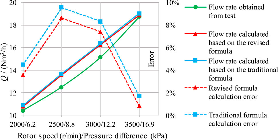
Figure 11. Comparison between test results and calculation results.
5 Conclusion
Aiming at the blank of the calculation formula of leakage flow in the working clearance of HCP, we establish a series of HCP models with different working clearances, analyze and compare the calculation accuracy of the traditional Roots blower leakage flow formula by using the simulation method, revised the formula based on the pressure distribution in the pump cavity, and verify the calculation accuracy of the two type formulas based on the test data. This research provides theoretical guidance for the reasonable design of the clearance dimension of HCP. The main conclusions are as follows:
(1) The traditional Roots blower clearance leakage flow calculation formula is relatively reliable when applied to the HCP. Using this formula to calculate a series of HCP models with different working clearances, the obtained flow values are close to the simulation results, with a minimum error of 0.99% and a maximum error of 10.71%.
(2) The traditional Roots blower clearance leakage flow calculation formula is revised based on the pressure distribution law in the pump cavity. Compared with the simulation results, the calculation error of the correction formula is better than that of the traditional formula, and the average calculation error of the 8 models has decreased from 5.75% to 3.82%.
(3) The calculation accuracies of the formulas are verified and compared through prototype testing data. The flow rate values obtained from the formulas are higher than the test values, but the calculation error of the correction formula is lower than that of the traditional formula.
6 Recent developments and future directions
In this paper, although the correction formula has higher calculation accuracy compared to the traditional formula, there is still a significant error between the calculated results and actual test data. One reason is that the clearance structure of the HCP will change due to the thermal deformation of the rotor and pump body during actual operation, further affecting the leakage flow rate. In the later stage, we will consider the influence of the temperature factor in the correction process of the clearance leakage flow calculation formula to further improve the calculation accuracy.
Data availability statement
The original contributions presented in the study are included in the article/Supplementary Material, further inquiries can be directed to the corresponding author.
Author contributions
HZ: Conceptualization, Funding acquisition, Writing–original draft. WL: Methodology, Resources, Writing–review and editing. XC: Data curation, Writing–review and editing. HM: Software, Writing–review and editing. YX: Software, Writing–review and editing.
Funding
The author(s) declare that financial support was received for the research, authorship, and/or publication of this article. The work was sponsored by the “Blue Project” of Jiangsu Colleges and Universities, the sixth phase of the “169 Project” of Zhenjiang, the visiting and training programs for teachers in Jiangsu colleges.
Conflict of interest
Author YX was employed by Beijing Drainage Group.
The remaining authors declare that the research was conducted in the absence of any commercial or financial relationships that could be construed as a potential conflict of interest.
Publisher’s note
All claims expressed in this article are solely those of the authors and do not necessarily represent those of their affiliated organizations, or those of the publisher, the editors and the reviewers. Any product that may be evaluated in this article, or claim that may be made by its manufacturer, is not guaranteed or endorsed by the publisher.
References
Chen, Z., Zuo, W., Zhou, K., Li, Q., and Huang, Y. (2023a). Multi-objective optimization of proton exchange membrane fuel cells by RSM and NSGA-II. Energy Convers. Manag. 277, 116691. doi:10.1016/j.enconman.2023.116691
Chen, Z., Zuo, W., Zhou, K., Li, Q., Huang, Y., and E, J. (2023b). Multi-factor impact mechanism on the performance of high temperature proton exchange membrane fuel cell. Energy 278, 127982. doi:10.1016/j.energy.2023.127982
Chen, Z., Zuo, W., Zhou, K., Li, Q., Yi, Z., and Huang, Y. (2024). Numerical investigation on the performance enhancement of PEMFC with gradient sinusoidal-wave fins in cathode channel. Energy 288, 129894. doi:10.1016/j.energy.2023.129894
Chen, Z., Zou, Y., and Jiang, Z. (2017). Numerical simulation of the effect of the gap between rotor and pump on the performance of the rotor pump. Noise Vib. Control, 37(2):62–66.
Chiu-Fan, H. (2015). A new curve for application to the rotor profile of rotary lobe pumps. Mech. Mach. Theory 87, 70–81. doi:10.1016/j.mechmachtheory.2014.12.018
Gu, P., Xing, L., Wang, Y., Feng, J., and Peng, X. (2020). Transient flow field and performance analysis of a claw pump for FCVs. Int. J. Hydrogen Energy 46, 984–997. doi:10.1016/j.ijhydene.2020.09.154
Gu, P., Xing, L., Wang, Y., Feng, J., and Peng, X. (2021). A multi-objective parametric study of the claw hydrogen pump for fuel cell vehicles using taguchi method and ANN. Int. J. Hydrogen Energy 46 (9), 6680–6692. doi:10.1016/j.ijhydene.2020.11.186
Huanle, Z., Wei, L. I., Leilei, J. I., Awais, M., Li, J., and Li, S. (2022). Profile design and performance research of hydrogen circulation pump in fuel cell system. Mechanika 28 (4), 283–293. doi:10.5755/j02.mech.31528
Huanle, Z., Wei, L. I., Leilei, J. I., Li, S., Cao, Y., and Li, Y. (2023). Research on measurement method for high-frequency pulsation flow of hydrogen circulating pump. Int. J. Hydrogen Energy 48 (39), 14853–14865. doi:10.1016/j.ijhydene.2022.12.358
Jia, Y., Yang, D. C. H., and Tong, S.-H. (2009). A new gerotor design method with switch angle assignability. J. Mech. Des. 131 (1). doi:10.1115/1.3013442
Joshi, M. A., Blekhman, I. D., Felske, D. J., Lordi, J. A., and Mollendorf, J. C. (2006). Clearance analysis and leakage flow CFD model of a two-lobe multi-recompression heater. Int. J. Rotating Mach. 2006. doi:10.1155/ijrm/2006/79084
Lin, J., Zhang, L., Dong, L., Liu, H., and Dai, C. (2021). Rotor profile design and motion simulation analysis of hydrogen circulating pump. Int. J. Fluid Mach. Syst. 14 (4), 322–334. doi:10.5293/ijfms.2021.14.4.322
Liu, L., Chen, P., Du, J., and Wang, X. (2020a). Study on involute rotor profile based on pressure angle reduction. J. Phys. Conf. Ser. 1550 (4), 042002. doi:10.1088/1742-6596/1550/4/042002
Liu, Y., Fan, L., Pei, P., Yao, S., and Wang, F. (2018). Asymptotic analysis for the inlet relative humidity effects on the performance of proton exchange membrane fuel cell. Apply Energy 213, 573–584. doi:10.1016/j.apenergy.2017.11.008
Liu, Z., Chen, J., Liu, H., Yan, C., Hou, Y., He, Q., et al. (2020b). Anode purge management for hydrogen utilization and stack durability improvement of PEM fuel cell systems. Appl. Energy 275, 115110. doi:10.1016/j.apenergy.2020.115110
Peng, Z., Liejiang, W. E. I., and Jianwei, L. I. Research on flow characteristics of vane pump based on laminar rectangular clearance leakage. Chin. Hydraulics Pneumatics, 2023, 47(3): 60–67.
Qin, L. I., Hui, W., and Huang, Z. Research on influence of meshing clearance and number of rotor blades on pump performance. Chin. J. Process Eng.,2022, 22(12):1666–1675.
Rao, L., and Zhong, Y. (2021). Axial clearance effects on performance of gerotor pump using numerical simulation. Mach. Build. Automation 50(5):110–112.
Shuo, L. I., Wei, L. I., Leilei, J. I., Zhai, H., Li, Y., Wang, C., et al. (2023). Effect of pressure ratio on transient flow in hydrogen circulating pump. Int. J. Hydrogen Energy 48 (69), 26937–26950. doi:10.1016/j.ijhydene.2023.03.370
Wang, J., Jiang, X., and Cai, Y. (2015). Investigation of a novel circular arc claw rotor profile for claw vacuum pumps and its performance analysis. Vacuum 111, 102–109. doi:10.1016/j.vacuum.2014.10.003
Wang, Y., and Ma, Q. (2019). “Fuel cell engine Technology overview,” in Fuel cell vehicle technologies, 42–47.
Wilhelm, W., Thomas, U., and Sven, S. (2020). Hydrogen pump for hydrogen recirculation in fuel cell vehicles. E3S Web Conf. 155, 01001. doi:10.1051/e3sconf/202015501001
Wu, G., Dasuo, Y. A. O., and Ning, J. I. (2023). Optimization of structural parameters of proton exchange membrane fuel cell ejector. Chin. Hydraulics Pneumatics 47 (3):115–122.
Xiang, L. I. N., and Lin, J. (2022). Design of working clearance and study on characteristics of hydrogen circulation pump. Pump. Technol. (4), 16–22+26.
Xing, L., Jianmei, F., Chen, W., Xing, Z., and Peng, X. (2020). Development and testing of a Roots pump for hydrogen recirculation in fuel cell system. Appl. Sci. Basel 10 (22), 8091. doi:10.3390/app10228091
Xing, Y., Yibin, Li, and Zhang, S. (2023). Effects of helical angle on performance and flow pulsation characteristics of aviation fuel gear pump. J. Propuls. Technol. 44 (03), 142–153.
Yibin, Li, Guo, D., and Tang, Y. (2020). Effect of the rotor diameter-length ratio on the rotary lobe pump performance based on numerical simulations and experimental tests. J. Vib. shock 39 (09), 194–200+220.
Zhengxian, L. I. U., Lianhuan, X. U., and Zhao, X. (2007). Revising formula for inside leakage flux of generic three-lobe Roots blower. Fluid Mach. (06), 28–31.
Zhou, S., Fan, L., Zhang, G., Gao, J., Lu, Y., Zhao, P., et al. (2022). A review on proton exchange membrane multi-stack fuel cell systems: architecture, performance, and power management. Appl. Energy 310, 118555. doi:10.1016/j.apenergy.2022.118555
Zhu, J., Dong, Q., and Geqiang, L. I. (2022). Effect of tooth tip clearance on leakage and cavitation characteristics of double-circular-arc spiral gear pump. Chin. Hydraulics Pneumatics 46 (7), 104–111.
Zuo, W., Li, F., Li, Q., Chen, Z., Huang, Y., and Chu, H. (2024b). Multi-objective optimization of micro planar combustor with tube outlet by RSM and NSGA-II for thermophotovoltaic applications. Energy 291, 130396. doi:10.1016/j.energy.2024.130396
Keywords: hydrogen circulation pump (HCP), radial clearance, axial clearance, leakage flow, calculation formula
Citation: Zhai H, Li W, Chu X, Mu H and Xu Y (2024) Research of the calculation formula for working clearance leakage flow of the hydrogen circulation pump. Front. Energy Res. 12:1414926. doi: 10.3389/fenrg.2024.1414926
Received: 09 April 2024; Accepted: 17 June 2024;
Published: 02 September 2024.
Edited by:
Yongfei Yang, Nantong University, ChinaReviewed by:
Wei Zuo, Wuhan University of Science and Technology, ChinaXiaoping Jiang, Nanjing Agricultural University, China
Tian Zuzhi, China University of Mining and Technology, China
Copyright © 2024 Zhai, Li, Chu, Mu and Xu. This is an open-access article distributed under the terms of the Creative Commons Attribution License (CC BY). The use, distribution or reproduction in other forums is permitted, provided the original author(s) and the copyright owner(s) are credited and that the original publication in this journal is cited, in accordance with accepted academic practice. No use, distribution or reproduction is permitted which does not comply with these terms.
*Correspondence: Huanle Zhai, anN6aGFpaGxAMTYzLmNvbQ==