 Xuliang Zhang1
 Bangtang Yin
- 1PetroChina Tarim Oilfield Company, Korla, China
- 2School of Petroleum Engineering, China University of Petroleum (East China), Qingdao, China
The risk of well control is high when displacement gas kick occurs in the deep fractured reservoir, and improper handling can easily lead to blowout, which will seriously affect the deep well drilling. Using Fluent software, a simulation model was constructed to depict the interaction of a horizontal well with vertical fractures. The displacement gas kick process was simulated in horizontal well under formation temperature and pressure conditions. An analysis was conducted to assess the impact of fracture width, quantity, as well as the viscosity and density of drilling fluid on the process of gas-liquid displacement. It further compared the effectiveness of three measures in counteracting displacement gas kick: applying back pressure at the wellhead, altering the viscosity and density of the drilling fluid. New findings suggest that the gas-liquid interface within the fracture exhibits a funnel-like shape, where the gas and liquid phases are layered in the annulus and manifest in a streak-like pattern. Fracture width, quantity, and drilling fluid density promote displacement, while drilling fluid viscosity inhibits the displacement. Different from vertical wells, in horizontal wells, displacement gas kick mainly appears in the underbalanced interval. The fracture width primarily determines the size of the displacement window, while the density and viscosity of the drilling fluid exert lesser influence. Horizontal wells are highly sensitive to variations in external conditions when it comes to displacement gas kick. Therefore, enhancing the wellhead back pressure is advisable to address the displacement gas kick in horizontal wells.
1 Introduction
As the utilization of oil and gas resources continues unabated, the focus of global oil resources exploitation has gradually shifted from areas with low exploitation difficulty to areas with harsh environment and difficult exploitation (Mu and Ji, 2019). Among them, deep carbonate reservoirs constitute approximately 70% of the global total oil reserves and approximately 50% of the confirmed reserves (Burchette, 2012). However, these reservoirs are characterized by deep burial, complex geological conditions, narrow safety pressure window, significant heterogeneity and extensive natural fracture networks (Pal et al., 2018; Tan et al., 2022). When encountering such deep reservoirs during drilling, overflow and leakage may occur simultaneously, namely, gravity displacement gas kick (Wang et al., 2012; Lee, 2015). Unlike conventional negative pressure gas kick, gravity displacement gas kick is accompanied by severe well loss (Xu et al., 2016), making it difficult to detect in a timely manner. Compared to vertical wells, horizontal wells have a greater contact area with the formation and may encounter multiple fractures simultaneously, which means that gas accumulation in the horizontal section can be significant and difficult to detect. These lead to the fact that it is often difficult to kill wells when displacement gas cut occurs, and the risk of well control is high (Akimov et al., 2010).
Bennion (1995,1998) pointed out for the first time that overflow and loss might occur at the same time when the formation with vertical fractures was encountered during underbalanced drilling. Unfortunately, the insufficient comprehension of mechanism underlying the coexistence of gas kick and loss circulation often leads to the misconception that this phenomenon is merely a case of gas kick (Meng et al., 2015; Li et al., 2016) or leakage (Zhang et al., 2012), ignoring the complexity of the interaction between the two. Petersen (1998) used RF-Kick Simulator to simulate the occurrence of gas kick under the condition of loss circulation. Subsequent scholars also used a similar experimental device to simulate the phenomenon of gravity displacement gas kick (Shu, 2012; Zhou 2017; Hou et al., 2018; Li et al., 2018). Such devices are generally composed of a system encompassing wellbore, fractures and formations, a circulatory network, and a system for acquiring data.
In addition to experimental methods, subsequent scholars have also combined numerical simulation methods to study displacement gas intrusion. Zhao (2015) conducted simulations of gas-liquid displacement in vertical wells, utilizing the Volume of Fluid (VOF) method. The findings reveal that the occurrence of gas-liquid displacement is contingent upon the fracture width, and the quantity of gas influx during each instance is minimal. Gravity displacement may occur when the pressure within the wellbore exceeds the pressure of surrounding formation. Xiao (2018) formulated a mathematical model pertaining to gas-liquid displacement. Based on the gravity replacement simulation experiment of drilling cracks in vertical wellbore, the model was verified. The experimental findings indicate that the fracture width is the primary factor influencing the loss circulation and gas kick rate, with the bottom hole pressure difference serving as a secondary factor. Ma (2020) used CFD technology to simulate the phenomenon of gas-liquid replacement in fractured gas reservoirs drilled in vertical annulus, and designed experiments using response surface method (RSM) to determine the liquid density, viscosity, fracture width and wellbore pressure difference. The influence degree of displacement gas kick established an empirical formula for gas influx rate. Tang (2022) used CFD technology to numerically simulate the law of gravity replacement, and obtained the change of loss circulation and gas kick rate under the conditions of constant pressure and closed boundary, and established a simplified gravity replacement model of fractured formation. Based on simulation, Peng et al. (2023) conducted an analysis of the process and determining factors involved in gas-liquid displacement when drilling vertical fractures in vertical wells. At present, the displacement process is predominantly studied through the utilization of visual experiments and numerical simulation techniques, and gas-liquid displacement mechanism. The focus is primarily on gas-liquid displacement in the vertical well. There is relatively less research about displacement in horizontal well. The dynamic process and mechanism of displacement gas kick in horizontal wells are unclear, and well control is difficult.
Therefore, in this work, utilizing Fluent software, a simulation model was developed for horizontal well drilling targeting a vertical fracture, aiming to describe the gas-liquid displacement process under the specific formation temperature and pressure conditions. Experiments at different fracture widths, fracture number, drilling fluid viscosities and densities were conducted to explore the behavior of gas kick and loss of circulation, assess the influence of diverse parameters on the displacement pressure window, and understand the mechanisms underlying handling measures for the displacement process.
2 Methods
2.1 Model construction
To investigate the gas-liquid displacement process and the effect of different parameters on the displacement in horizontal well, making the conditions closer to actual wellbore conditions, a geometric model was established depicting a horizontal well crossing vertically with fractures using ANSYS software. The model includes three fracture widths (1, 3, 6 mm) and three fracture quantities (single fracture with a width of 3 mm, two fractures with a width of 3 mm, three fractures with a width of 3 mm). Specific geometric model parameters are shown in Table 1. The geometric model, as shown in Figure 1, takes the single fracture model as an example, the right end of the wellbore is designated as the velocity inlet, admitting the inflow of drilling fluid, while the left end serves as the pressure outlet boundary, facilitating the outflow of drilling fluid and gas. To maintain a constant gas source pressure, the pressure inlet boundary is established on both sides of the fracture, while the remaining boundaries are designated as walls.
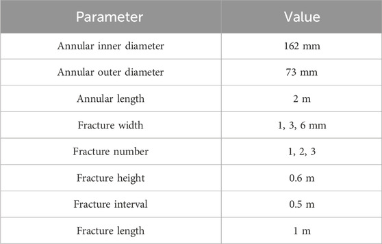
Table 1. Geometric parameters of the simulation model.
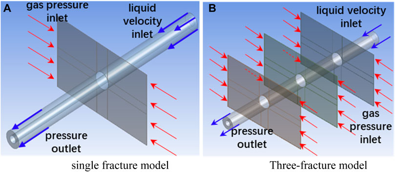
Figure 1. Model view. (A) single fracture model. (B) Three-fracture model.
2.2 Mesh subdivision
The multiple region method was used for mesh partitioning in the fracture area, while the sweeping method was used for mesh partitioning in the annular wellbore area. Considering that the flow state in the intersecting area between the fractures and the wellbore may be chaotic, local mesh refinement was applied to that intersection. Taking the three-fracture model as an example, the mesh partitioning is shown in Figure 2. Table 2 is the specific mesh parameters.
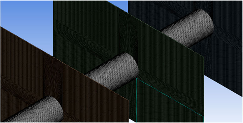
Figure 2. Gridding diagram of fracture part.
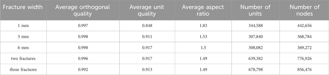
Table 2. Finite element model mesh parameters.
In Table 2, the orthogonality quality is the vector from the center of one computational cell to the center of its adjacent cell, with values less than one being desirable, as values closer to one indicate better quality. The aspect ratio of the grid refers to the ratio of the longest side to the shortest side of a cell. The closer this value is to 1, the closer the cell is to a cube, resulting in better grid calculation results. The unit quality of grid cells is a function of edge length to volume used by Fluent to describe grid quality, with values less than one indicating better quality as they approach 1. Therefore, Table 2 indicates a good quality grid partitioning.
2.3 Solving parameters
The gravity drainage displacement process involves the gas-liquid flow, and the characteristics of the two phase interface are the important part of simulation. Therefore, the VOF model was selected as the multiphase flow model to simulate this process.
Volume fraction can be calculated based on Eqs 1, 2 (Hirt and Nichols 1981).:
In which,
Based on the viscosity and density range of drilling fluid used on-site, set the liquid phase viscosity range to 20–60 mPa·s and the density range to 1,200–1800 kg/m3 in the simulation. Table 3 presents the key parameters utilized in the simulation calculations.
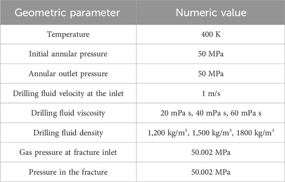
Table 3. Simulation parameters.
2.4 Grid independence verification
In CFD simulation calculations, the size of the grid cells during grid partitioning is closely related to the computational results of the model. When the cell size is large, the number of grids is too small, which may result in floating-point overflow errors during simulation. Conversely, when the cell size is small, there are too many grids, resulting in normal calculation results but consuming excessive computing power and time. Therefore, it is necessary to select an appropriate number of grids to ensure normal calculation results without consuming excessive computing power. In this study, four minimum cell sizes(6, 3, 2, 1 mm) were selected to partition the single fracture model, and simulation calculations were performed in Fluent under the boundary conditions listed in Table 3 (liquid viscosity 20 mPa·s, density 1,200 kg/m3), comparing the simulation results under different numbers of grids. The relationship between leakage rate, gas kick rate, and the number of grids obtained is shown in the following figure.
From Figure 3, it can be seen that after the number of grids exceeds 307,840(cell sizes 3 mm), the simulated leakage rate and gas invasion velocity change very little with the increase in the number of grids. It can be considered that at this point, the simulation results are no longer correlated with the number of grids. Therefore, in subsequent grid partitioning, a minimum cell size of 3 mm is chosen.
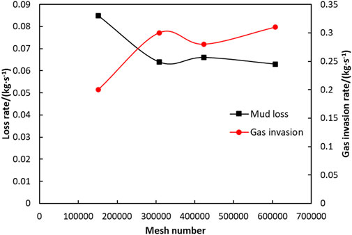
Figure 3. Grid independence test results.
2.5 Model verification
Li et al. (2020) conducted a study on the mechanism of drilling-induced formation leakage and coexistence through simulation experiments. In order to investigate the impact of viscosity on gravity displacement, the experiment employed water as well as a fluid exhibiting a viscosity of 10 mPa·s. The accuracy of the established simulation model was confirmed by comparing it with experimental results in prior literature. Table 4 presents the key parameters of the experimental apparatus utilized in this literature.
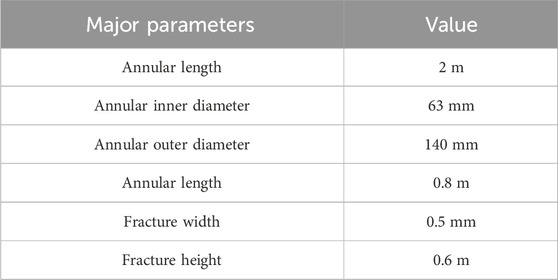
Table 4. Principal specifications of the experimental apparatus.
A geometric model with the same experimental dimensions was constructed to compare the loss circulation and gas kick under experimental and simulation conditions. Figure 4 illustrates the comparison between simulation and experimental results. The real line represents the experimental value, and the imaginary line represents the simulated value. The pressure difference is the annular pressure of the horizontal section minus the initial pressure of the fracture.
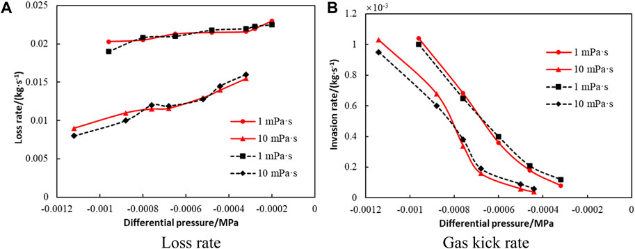
Figure 4. Comparison of loss rates and gas kick rates from the simulation and experiment under different bottom-hole pressure differences. (A) Loss rate. (B) Gas kick rate.
By comparing simulation and experimental results, it can be observed that the simulation results demonstrate close alignment with the experimental findings, with errors within 15%. This indicates that the established simulation model and parameter settings are reasonable, which can thus be effectively employed in simulating gas-liquid displacement in fractured formation encountered during horizontal well drilling, considering the reservoir’s temperature and pressure.
3 Results and discussion
3.1 Gas-liquid displacement process
According to the simulation results, once the gas influx into the wellbore, the drilling fluid and the gas will flow together. Based on the extracted data, it is evident that the gas outflow velocity maintains a consistent rate, accumulating above the annulus to form a strip-shaped gas film. Due to the force of gravity, the drilling fluid enters the fracture located within the annulus and accumulates beneath it. Due to gas inflow from both sides, a situation of drilling fluid leakage with a wide middle and narrow sides is formed. Figure 5 illustrates the gravity displacement phenomenon, where the red color signifies the gaseous component, the blue color designates the liquid component, and the green color indicates the gas-liquid mixture region.
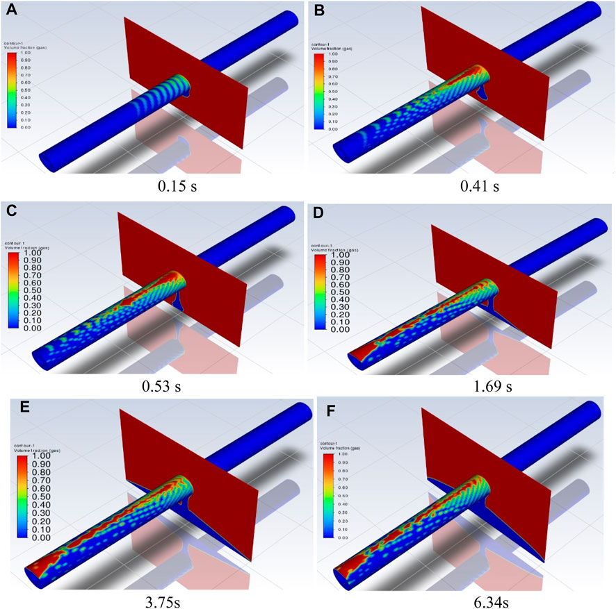
Figure 5. Dynamic process of gravity displacement. (A) 0.15 s, (B) 0.41 s, (C) 0.53 s, (D) 1.69 s, (E) 3.75 s, (F) 6.34 s.
It can be observed that in the gravity displacement process, the gas in the fracture first enters the annulus to form bubbles, which flow unstably in the annulus, and then gradually gather to form strip-shaped gas films. On the contrary, the drilling fluid flows vertically downward within the fracture, ultimately reaching its base and gradually accumulating to occupy the entire volume of the fracture. If gas kick is severe, the strip-shaped gas films in the annulus will converge and flow in the upper part of the annulus. The diagram below depicts the ultimate distribution of the gas-liquid interface within the fracture. Comparing Figures 6A, B, it can be seen that after gas-liquid gravity displacement in horizontal and vertical wells, the gas-liquid interface in the fracture appears as “peak-shaped”. The difference is that in vertical wells, the gas-liquid displacement interface forms half of a peak, while in horizontal wells, it forms a complete peak. This is because the horizontal well penetrates the fracture completely, and gas-liquid displacement occurs on both sides of the annulus; whereas gas-liquid displacement in the vertical well section only occurs on one side of the fracture. Therefore, it can be considered that the mechanism and process of gas-liquid displacement in horizontal and vertical wells are similar, with the driving force of displacement being pressure difference and density difference.
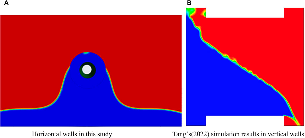
Figure 6. Gas-liquid distributions in the fracture. (A) Horizontal wells in this study, (B) Tang et al. (2022) simulation results in vertical wells.
3.2 Impact factor analysis
To explore the impacts of various factors such as fracture width, drilling fluid density, viscosity, and the number of fractures on the horizontal well displacement gas kick, simulations of gas-liquid displacement under different parameters were conducted. Keeping the bottom hole pressure constant at 50 MPa, the fracture’s entrance pressure was gradually adjusted from a lower to a higher value, observing single gas kick, gas-liquid displacement, and single leakage phenomena, attaining the gravity displacement window under varying scenarios. The intersection surface of the fracture and annulus was set as the monitoring surface to observe the gas and liquid mass flow rate passing through this surface, thereby exploring the variations in gas kick rate and leakage rate with changes in operating conditions.
Figure 7 exhibits the varying trends of gas kick and leakage rates with fracture pressure for various fracture widths. The intervals where both leakage rate and gas kick rate are greater than 0 represent the gravity displacement window. It can be observed that gravity displacement occurs in both the underbalanced and overbalanced regions. A comparison of gravity displacement windows across various fracture widths reveals that an increase in fracture width enhances gravity displacement. Specifically, a wider fracture leads to a larger gravity displacement window, making gravity displacement phenomenon more likely to occur. As the width increases, there is a tendency for the window to expand towards the underbalanced region. This observation can be attributed to the fact that a wider fracture reduces the resistance encountered by the drilling fluid as it enters the fracture. Conversely, gas needs to “push back” against more drilling fluid. It becomes more challenging for the gas to enter the annulus. Consequently, a higher fracture pressure is required to facilitate the diffusion of gas into the annulus.
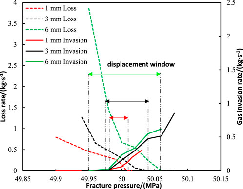
Figure 7. Influence of fracture width on gas-liquid displacement window.
Figure 8 depicts the relationship between gas kick and leakage rate, as they vary with fracture pressure for various drilling fluid viscosities. An increase in viscosity is observed to have an inhibitory effect on gravity displacement. Specifically, a higher liquid viscosity results in a smaller gravity displacement window. This occurs because, given a constant fracture width, an increase in drilling fluid viscosity leads to an increase in flow resistance, thereby hindering the flow of drilling fluid into the fracture. On the other hand, as gas migrates within the annulus, it encounters greater resistance due to the increased viscosity of the liquid phase, which hinders the continuous entry of gas into the annulus. Hence, a higher fracture pressure is required to initiate the displacement process, leading to the displacement window primarily residing in the underbalanced region.
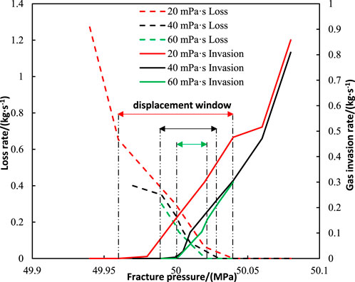
Figure 8. Effect of drilling fluid viscosity on gas-liquid displacement window.
Figure 9 illustrates the varying trends of gas kick and leakage rate with fracture pressure across various drilling fluid densities. It can be observed that increasing drilling fluid density will enlarge the displacement window, making displacement phenomena more likely to occur. This is because the increase in liquid density will make the driving force of gravity more significant. Under the same conditions, liquid with higher density is more prone to fall into the fracture under the influence of gravity. Additionally, the downward movement of the liquid does not significantly hinder the lateral diffusion of gas into the annulus. Therefore, after increasing the liquid density, the displacement window does not need to expand further towards the underbalanced direction. Some displacement phenomena will also occur in the overbalanced region.
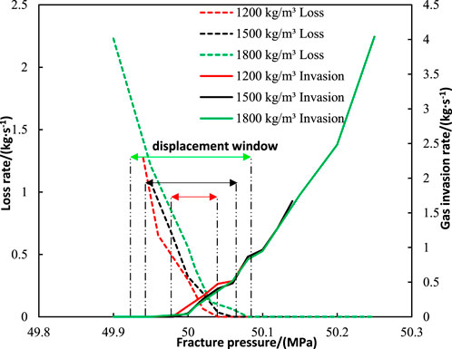
Figure 9. Impact of drilling fluid density on gas-liquid displacement window.
Given the abundance of fractures in fractured formations, the impact of fracture quantity on gravity displacement gas kick in horizontal wells was explored. As depicted in Figure 10, the gravity displacement windows vary significantly with the number of fractures. It is evident that an escalation in the quantity of fractures enhances the likelihood of gravity displacement gas kick. Specifically, a higher number of fractures results in a larger gravity displacement window. Furthermore, in the model with a greater number of fractures, both the leakage and gas kick rate are marginally higher compared to the single fracture model. It is evident that as the drilling length of horizontal wells extends, encountering more fractures, the gravity displacement window will become larger. In practical engineering, horizontal wells with large lengths should pay more attention to the possibility of gravity displacement gas kick and be cautious in controlling pressure to avoid being close to underbalanced conditions.
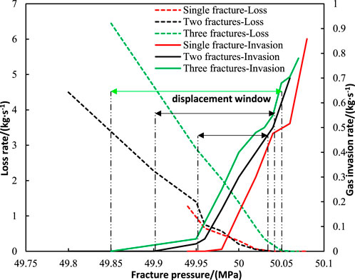
Figure 10. Gravity displacement window of each fracture number.
3.3 Mechanism of gravity displacement in horizontal well
After examining the occurrence conditions of simultaneous loss and overflow of gravity displacement origin in vertical well, Shu (2012) concluded that the cause of the displacement was that: in the section where the wellbore intersects with the fracture, if the drilling fluid pressure gradient within wellbore exceeds the gas pressure gradient within the fracture, a specific location can be identified where the wellbore pressure and the fracture pressure are equivalent. Above this position, the wellbore pressure is lower than the gas pressure, leading to an overflow occurrence. Conversely, below this position, the pressure of the drilling fluid is higher than the gas pressure, resulting in a loss. This phenomenon, characterized by an overflow at the upper end and a loss at the lower end, is known as displacement gas kick and occurs specifically in the section where the wellbore intersects with the fracture.
As shown in Figure 11, the condition that the vertical well section only has loss but no overflow is:
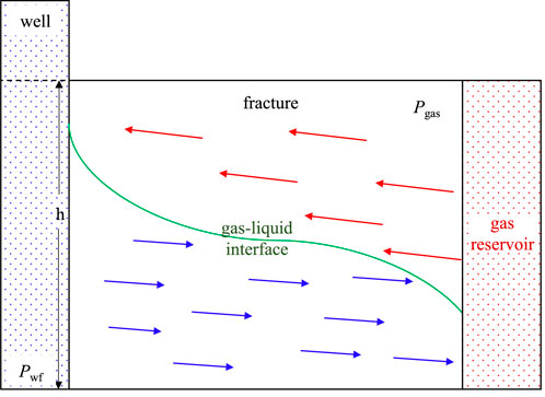
Figure 11. Sketch of displacement gas kick in vertical well section.
The condition that the vertical well section has only overflow but no loss is:
The condition that the vertical well section has overflow and loss simultaneously is:
Disregarding the impact of interfacial tension, the concurrent occurrence of overflow and loss can be reformulated as the following condition:
Finally, it is simplified as:
In the formula, h is the height of fracture, m;
It is evident that the occurrence of gravity displacement in the vertical well section primarily hinges on the density of the drilling fluid
According to Section 3.1, the comparison of gas-liquid displacement interfaces between horizontal and vertical wells indicates that when the horizontal well section encounters a fracture, the physical process of both overflow and loss remains identical to that observed in the vertical well section. Consequently, the analysis of its occurrence can be approached in a similar manner, as exemplified in Figure 12. However, the key difference lies in the alteration of the gas-liquid intersection surface’s height, which shifts from the fracture height h to the annulus’s outer diameter
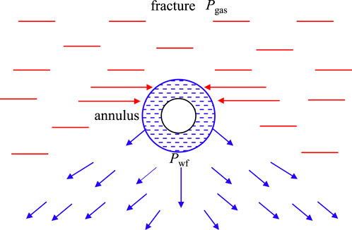
Figure 12. Illustration of gas-liquid displacement in horizontal wellbore section.
Hence, in comparison to the vertical well section, the displacement window of the horizontal well section encountering a vertical fracture theoretically decreases by several folds, and the impact of drilling fluid density on the displacement window is also diminished.
3.4 Strategies to mitigate gas-liquid displacement in horizontal well
Generally, gravity displacement occurs in vertical well balanced drilling. Due to the non-underbalanced condition, the occurrence is relatively hidden and easily overlooked during on-site operations, leading to potential losses. By applying back pressure, increasing viscosity, and simultaneously increasing viscosity and density to horizontal wells experiencing gravity displacement gas kick, the well control methods for this scenario are investigated. Simulations of the three measures are conducted for the same duration, with specific parameters as shown in Table 5, and the corresponding well control effects are illustrated in Figure 13.
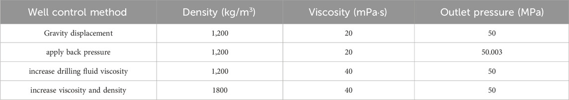
Table 5. Well control application parameters.
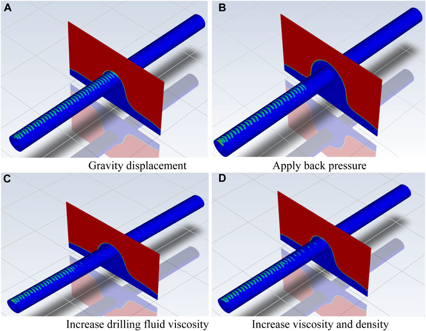
Figure 13. Well control effect of gravity displacement gas kick. (A) Gravity displacement, (B) Apply back pressure, (C) Increase drilling fluid viscosity, (D) Increase viscosity and density
From Figure 13B, it can be observed that after applying back pressure, gas no longer enters the annulus. An increased amount of drilling fluid penetrates into the fracture. This indicates that gravity displacement has transitioned to a leak, which indicates that the pressure difference at the bottom of the hole is no longer contained within the range of the gravity displacement window.
As observed in Figure 13C, upon increasing the viscosity of the drilling fluid, gas is prevented from entering the annulus. This demonstrates that viscosity serves as an effective deterrent against gravity displacement, resulting in a reduced size of the displacement window.
As shown in Figure 13D, despite increasing both the density and viscosity of the drilling fluid, gas can still gradually penetrate into the annulus within the fracture. This occurs due to the density difference being the primary driving force for gravity displacement. Although increasing the liquid phase density will increase the leak rate and displacement window, leading to a less significant inhibitory effect on displacement gas kick compared to solely increasing the liquid phase viscosity.
By comparing Figures 13A–D, it can be seen that horizontal well drilling encountering gravity displacement in fractures is quite sensitive to wellhead back pressure, liquid phase viscosity, and density. Slight changes in conditions can affect the occurrence of displacement gas kick in horizontal wells. Among these factors, wellhead back pressure has the best inhibitory effect on displacement gas kick.
4 Conclusion
(1) A simulation model was developed for horizontal well drilling encountering a vertical fracture, aiming to replicate the dynamic process of gas-liquid displacement in a horizontal well intersecting a fractured formation. During the displacement process, it was observed that the gas-liquid interface exhibited a funnel-like shape within the fracture. Subsequently, as the gas diffused into the annulus, it separated from the liquid phase and formed a strip-like gas film at the upper portion of the annulus.
(2) The width of the fracture, the density of the drilling fluid, and the number of cracks all contribute to the occurrence of displacement, whereas the viscosity of the drilling fluid serves to restrain it. In horizontal wells, the window for gravity displacement to occur is narrow and primarily situated within the underbalanced range.
(3) The differences between displacement gas kick in vertical well and that in horizontal well were analyzed theoretically. Different from the vertical well section, the primary driving force behind displacement in the horizontal well section is the difference in pressure, the drilling fluid density and fracture height have smaller effects, and the displacement interval reduces several times in theory.
(4) The occurrence of displacement phenomenon is sensitive to changes in fluid properties and wellhead pressure. To address the issue of displacement gas kick in horizontal wells, it is recommended to increase the wellhead backpressure.
(5) Due to its small size, the horizontal annulus model developed in this study may be subject to terminal effects that have a significant influence on the simulation outcomes. Additionally, this study did not consider the variable fracture spacing, thus necessitating the development of a more comprehensive model to delve deeper into the mechanisms underlying displacement gas kick in horizontal wells.
Data availability statement
The original contributions presented in the study are included in the article, further inquiries can be directed to the corresponding author.
Author contributions
XZ: Writing–original draft; Formal analysis; Investigation; Methodology. TD: Formal analysis; Validation; Investigation; Writing–original draft. BZ: Writing–Original draft; Formal analysis; Data Curation. BY: Conceptualization; Methodology; Supervision; Investigation; Writing–original draft; Writing–Review and Editing; Funding acquisition; Project administration.
Funding
The author(s) declare that financial support was received for the research, authorship, and/or publication of this article. This paper was sponsored by Natural Science Foundation of China (52274020 and U21B2069), the National Key Research and Development Program of China (2022YFC2806504).
Acknowledgments
The content of this manuscript has been presented IN PART, about 5% at the 2023 International Field Exploration and Development Conference, “Bangtang Yin, Tianbao Ding, Tianhao Dong, et al. Study on Displacement Gas Invasion Law During Horizontal Well Drilling in Fractured Gas Reservoir. Proceedings of the International Field Exploration and Development Conference 2023, IFEDC 2023, Springer Series in Geomechanics and Geoengineering. Springer, Singapore, 2024, 110-125.”. We recognize the support of China University of Petroleum (East China) for the permission to publish this paper.
Conflict of interest
Authors XZ and BZ were employed by PetroChina Tarim Oilfield Company.
The remaining authors declare that the research was conducted in the absence of any commercial or financial relationships that could be construed as a potential conflict of interest.
Publisher’s note
All claims expressed in this article are solely those of the authors and do not necessarily represent those of their affiliated organizations, or those of the publisher, the editors and the reviewers. Any product that may be evaluated in this article, or claim that may be made by its manufacturer, is not guaranteed or endorsed by the publisher.
Abbreviations
CFD, Computational fluid dynamics; RSM, Response surface method; VOF, Volume of Fluid.
References
Akimov, O. V., Zdolnik, S. E., Khudyakov, D. L., Tyapov, O. A., Gusakov, V. N., and Kraevskly, N. N. (2010). Well kill technologies with fluid loss control for hydro-fractured wells under ahfp and alfp conditions. Neft. khozyaistvo 2, 92–95.
Bennion, D. B., Thomas, F. B., Bietz, R. F., and Bennion, D. W. (1998). Underbalanced drilling: praises and perils. SPE Drill. Complet 13 (4), 214–222.
Bennion, D. B., Thomas, F. B., Bietz, R. F., and Bennion, D. W. (1998). “Underbalanced drilling, praises and perils-lab and field experience,” in SPE/CIM 5th One Day Annual Conference on Horizontal Well Technology, Canada, Calgary, 1995. SPE Drill. & Compl. 13(4), 214–222. doi:10.2118/52889-PA
Burchette, T. P. (2012). Carbonate rocks and petroleum reservoirs: a geological perspective from the industry. Geol. Soc. Lond. Spec. Publ. 370 (1), 17–37. doi:10.1144/sp370.14
Hirt, C. W., and Nichols, B. D. (1981). Volume of fluid (VOF) method for the dynamics of free boundaries. Journal of computational physics 39 (1), 201–225. doi:10.1016/0021-9991(81)90145-5
Hou, X., Zhao, X., Meng, Y., Yang, S., Li, G., and Liu, W. (2018). Liquid-liquid gravity displacement test based on experimental apparatus for real fractures. Pet. Drill. Tech. 46 (01), 30–36. doi:10.11911/syztjs.2018036
Lee, J. (2015). Reconstruction of ancestral drainage patterns in an internally draining region, Fars Province, Iran. Geol. Mag. 152 (5), 830–843. doi:10.1017/s0016756814000685
Li, G., Yang, M., Meng, Y., Wen, Z., Wang, Y., and Yuan, Z. (2016). Transient heat transfer models of wellbore and formation systems during the drilling process under well kick conditions in the bottom-hole. Appl. Therm. Eng. 93, 339–347. doi:10.1016/j.applthermaleng.2015.09.110
Li, J., Liu, G., Zhou, L., Tang, G., Xu, Z., Wang, T., et al. (2018). Gas-liquid gravity displacement experiment of fractured carbonate formation. Acta Pet. Sin. 39 (10), 1186–1192. doi:10.7623/syxb201810010
Li, H., Liang, J., Jia, H., Dong, M., Li, G., and Wu, P. (2020). Experimental and numerical investigation of Gas–Liquid gravity displacement in a horizontal well intersecting a vertical fracture. J. Nat. Gas Sci. Eng. 84, 103632. doi:10.1016/j.jngse.2020.103632
Ma, T., Tang, T., Chen, P., Li, Z., and Liu, S. (2020). Numerical investigation of gas-liquid displacement between borehole and gassy fracture using response surface methodology. Energy Sci. Eng. 8 (3), 740–754. doi:10.1002/ese3.547
Meng, Y., Xu, C., Wei, N., Li, G., Li, H., and Duan, M. (2015). Numerical simulation and experiment of the annular pressure variation caused by gas kick/injection in wells. J. Nat. Gas Sci. Eng. 22, 646–655. doi:10.1016/j.jngse.2015.01.013
Mu, L., and Ji, Z. (2019). Technologcial progress and development directions of PetroChina overseas oil and gas exploration. Petroleum Explor. Dev. 46 (6), 1088–1099. doi:10.1016/s1876-3804(19)60265-x
Pal, S., Mushtaq, M., Banat, F., and Al Sumaiti, A. M. (2018). Review of surfactant-assisted chemical enhanced oil recovery for carbonate reservoirs: challenges and future perspectives. Petroleum Sci. 15, 77–102. doi:10.1007/s12182-017-0198-6
Peng, C., Deng, Z., Fu, J., Cao, Q., Zhang, J., Li, Q., et al. (2023). Numerical simulation of gas–liquid gravity displacement in vertical fractures during drilling of carbonate formations. ACS omega 8 (9), 8846–8864. doi:10.1021/acsomega.3c00193
Petersen, J., Rommetveit, R., and Tarr, B. A. (1998). “Kick with lost circulation simulator, a tool for design of complex well control situations,” in SPE Asia Pacific Oil and Gas Conference and Exhibition, Perth, Australia, 1998. SPE-49956-MS.
Shu, G. (2012). Drilling overflow and loss coexistence flow in fractured formation. Chengdu: Southwest Petroleum University.
Tan, Y., Li, Q., Xu, L., Ghaffar, A., Zhou, X., and Li, P. (2022). A critical review of carbon dioxide enhanced oil recovery in carbonate reservoirs. Fuel 328, 125256. doi:10.1016/j.fuel.2022.125256
Tang, M., Yao, G., He, S., Huajun, L., Liu, S., and Lu, J. (2022). Gravity displacement gas kick law in fractured carbonate formation. J. Petroleum Explor. Prod. Technol. 12 (11), 3165–3181. doi:10.1007/s13202-022-01514-0
Wang, P. Q., Nie, X. Y., Zhang, X. M., Luo, P. Y., and Bai, Y. (2012). Study on a special association polymer gel applied in vicious lost circulation in crushed zones. Adv. Mater. Res. 518, 102–107. doi:10.4028/scientific.net/amr.518-523.102
Xiao, D., Meng, Y., Li, G., Shu, G., Li, S., and Guo, Y. (2018). Development of a mathematical model and experimental validation of borehole instability due to gravity displacement during drilling in a fractured formation. J. Petroleum Sci. Eng. 168, 217–225. doi:10.1016/j.petrol.2018.05.030
Xu, C., Kang, Y., Chen, F., and You, Z. (2016). Fracture plugging optimization for drill-in fluid loss control and formation damage prevention in fractured tight reservoir. J. Nat. Gas Sci. Eng. 35, 1216–1227. doi:10.1016/j.jngse.2016.09.059
Zhang, Z., Xiao, T. P., and Fu, J. H. (2012). Study on well-kill calculation model with deep-water engineer’s method. Adv. Mater. Res. 393, 996–999. doi:10.4028/www.scientific.net/AMR.393-395.996
Zhao, Z., Pu, X., Wang, G., Li, Z., Chen, L., and Cao, C. (2015). Numerical study of the gas-fluid displacement invasion behavior in a fractured carbonate reservoir. J. Nat. Gas Sci. Eng. 27, 686–691. doi:10.1016/j.jngse.2015.09.005
Keywords: horizontal well, deep fracture formation, displacement gas kick, displacement window, simulation
Citation: Zhang X, Ding T, Zhou B and Yin B (2024) Mechanism of displacement gas kick in horizontal well drilling into deep fractured gas reservoir. Front. Energy Res. 12:1412038. doi: 10.3389/fenrg.2024.1412038
Received: 04 April 2024; Accepted: 19 April 2024;
Published: 24 May 2024.
Edited by:
Feng Dong, China University of Geosciences, ChinaReviewed by:
Wenqiang Lou, Yangtze University, ChinaShihui Sun, Northeast Petroleum University, China
Liangbin Dou, Xi’an Shiyou University, China
Copyright © 2024 Zhang, Ding, Zhou and Yin. This is an open-access article distributed under the terms of the Creative Commons Attribution License (CC BY). The use, distribution or reproduction in other forums is permitted, provided the original author(s) and the copyright owner(s) are credited and that the original publication in this journal is cited, in accordance with accepted academic practice. No use, distribution or reproduction is permitted which does not comply with these terms.
*Correspondence: Bangtang Yin, eWluYmFuZ3RhbmdAMTYzLmNvbQ==