- College of Electrical Engineering, Shanghai University of Electric Power, Shanghai, China
Due to the EV (Electric Vehicles) charging stations are characterized by weak damping and low inertia, the EV with a high degree of uncertainty can easily have an impact on the stability of the charging station system. Therefore, this paper proposes an optimization control method to improve the system inertia effect based on the fractional order impedance model of the charging station. This paper presents a study on establishing a fractional impedance model for charging stations, using the deviation between theoretical impedance spectra and actual measurements as a criterion. The goal is to enhance system inertia and optimize the parameters of the fractional-order controller to improve the supporting capacity of the charging station system and enhance its dynamic response. Initially, considering the fractional characteristics of the EV load, a fractional impedance model of the charging station is established. The analysis demonstrates that the fractional-order capacitor provides inertia to the system, enhancing its inertia support capability. In addition, a virtual inertia control strategy based on fractional-order PID (FOPID) is designed. Finally, an improved particle swarm optimization algorithm is utilized to optimize the control parameters. Through experimental verification under different operating conditions, it has been demonstrated that the fractional-order control strategy can achieve a dynamic response time of approximately 0.025s and limit the voltage deviation within 5%. Furthermore, the rotational inertia can rapidly increase to the maximum value satisfying the objective function within 0.05s. The results indicate that this control method effectively suppresses the DC voltage and power oscillations in the distribution grid.
1 Introduction
In the face of dwindling oil reserves and escalating pollution from conventional fuel vehicles, there has been a growing national emphasis on promoting the adoption of new energy vehicles. This impetus has, in turn, propelled the development of essential infrastructure such as charging stations (Jinyuan et al., 2020). Presently, the structure of electric vehicle charging stations primarily involves the conversion of AC power from the distribution grid into stable DC power using rectifiers and power converters. The high prevalence of power electronic converters in the system renders charging stations susceptible to weak damping characteristics and low system inertia. As disturbances arise, such as load switching of electric vehicles and faults in the distribution grid, there arises a pressing need to bolster the system’s inertia support capacity to enhance overall stability and efficiency (Pengcheng et al., 2022).
In the field of electric vehicle research, there have been numerous studies conducted by scholars. Among these, Reference (Zhang and Xujian, 2022) utilized an equivalent circuit model combined with a three-dimensional finite element method to investigate the inconsistent distribution observed during charging and discharging processes in closed-loop coils. This led to the proposal of a new strategy involving multiple charging processes that enable precise charging to the target current. Reference (Lu et al., 2022) proposed an adaptive dynamic surface control method with disturbance observer, which enhances the control accuracy and stability of hybrid power source systems for electric vehicles. Based on the dual-model predictive control, Reference (Zhang et al., 2023) developed a method to achieve energy savings and stability for distributed electric vehicle driving. Reference (Jinhao et al., 2023) studied collector equipment in new energy vehicle batteries and proposed a lightweight network model that is both fast and stable. Reference (Yuan et al., 2023) proposed a regulation operation framework for plug-in electric vehicle (PEV) aggregators based on grid-to-vehicle technology and developed a PEV scheduling algorithm. This optimization scheduling method not only increases the aggregator’s revenue but also reduces the charging costs of electric vehicle owners. The study of electric vehicles (EVs) is currently highly regarded (Hou et al., 2017), with extensive research focused on modeling electric vehicle power batteries and energy storage. However, the connection between the charging process of electric vehicles and the grid, along with the associated control methodologies, remains a crucial topic of interest.
The components of capacitors and inductors within power electronic converters and electric vehicle battery systems exhibit fractional-order characteristics and diffusion properties (Macioszek, 2021). Traditional integer-order models struggle to accurately describe their distributed performance and memory effects, while fractional-order models extend the applicability beyond integer-order models, providing a better representation of the gradual parameter variations (Chen et al., 2024), yielding more precise charging station models. In recent years, the application of fractional calculus theory in fractional-order modeling has become increasingly prevalent (Zhou et al., 2021). The reference (Jing et al., 2020) reveals the distinct fractional-order impedance characteristics of batteries through their electrochemical impedance spectroscopy. By replacing integer-order capacitors with Constant Phase Elements (CPE), fractional-order models, as indicated in studies (Junfu et al., 2017; Zhou et al., 2022), can realistically simulate the polarization effects and charge-discharge characteristics of batteries. Additionally, the establishment of fractional-order Buck-Boost converters and three-phase grid-tied inverter models in references (Liao et al., 2023; Xiaocong et al., 2023) demonstrates that fractional-order models possess richer nonlinear characteristics and greater design flexibility. These research findings underscore the effectiveness of employing fractional-order theory for modeling power electronic devices and determining control strategies.
Numerous studies have demonstrated that various control methods, such as sliding mode control (Wang et al., 2023), predictive control (Guo et al., 2022), and fuzzy control, can effectively enhance the dynamic and steady-state performance of converters. However, challenges persist, including low inertia and insufficient damping. A common strategy for improving inertia involves treating the converter as a virtual synchronous machine, simulating the inertia and damping characteristics of a synchronous machine to provide the system with the necessary properties. This approach typically requires the addition of extra energy storage units in the design of the control strategy (Zisen et al., 2018; Gong and Gu, 2023). However, previous research has neglected the dynamic response of the energy storage units during the design phase of the control strategy. In a study referenced by (Linbin et al., 2017) the dynamic characteristics of DC capacitors are utilized to boost system inertia, and the impact of key parameters on dynamic behavior is thoroughly investigated.
Due to the flexibility and enhanced control effectiveness of fractional-order controllers, studies (Xiao et al., 2020; Lingling et al., 2022) have utilized fractional-order controllers to regulate both integer and fractional-order power electronic converter models. The findings indicate superior dynamic performance compared to integer-order controllers, effectively improving system stability. These studies commonly utilize the Integral of Time multiplied by Absolute Error (ITAE) performance index as the objective function for parameter optimization. However, in practical renewable energy systems, variations in power system and control parameters can modify impedance characteristics, making impedance modeling a more appropriate approach for engineering analysis (Dingyu, 2018; Chuang et al., 2021). The aforementioned research underscores that fractional-order control methods offer greater flexibility and superior control effectiveness when compared to integer-order control methods.
Based on the limitations outlined in the cited literature, this study employs fractional-order modeling techniques to better align the model with the actual characteristics of systems, thereby furnishing model support for the efficacy of subsequent control methodologies. The exceptional performance of fractional-order controllers enhances the flexibility of integer-order parameter design, thereby optimizing control outcomes. In various emerging applications within the realm of power systems, such as control systems for electric scooters (Macioszek et al., 2023), motorcycles, and charging stations for new energy vehicles, as well as in the large-scale charging control infrastructure for urban electric vehicle electronic transportation facilities (Macioszek, 2019), the inertia-optimized control method based on fractional-order models and controllers promptly furnishes adequate inertia to the system. This effectively mitigates oscillations in DC voltage and power at the distribution network side, ensuring the stable operation of the power system.
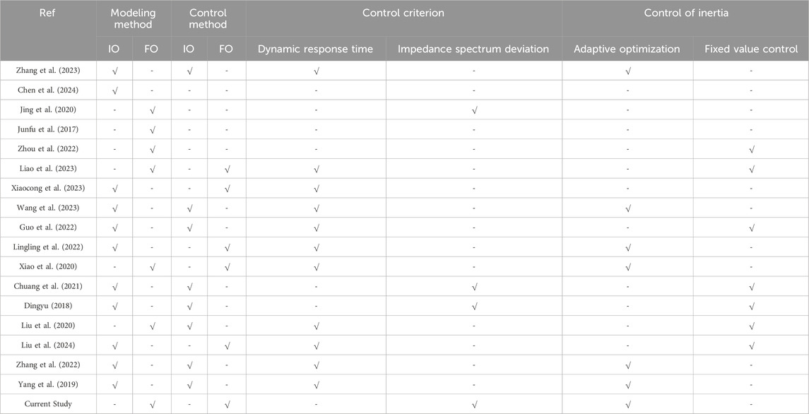
The analysis in Table 1 reveals a scarcity of studies utilizing fractional-order control methods in previous virtual inertia control, and even fewer that combine fractional-order models with fractional-order control methods for analysis. Given the prevalent fractional-order characteristics of power electronic devices in practical applications, particularly within the current context of extensive construction of electric vehicle charging stations, fractional-order modeling and control methods exhibit strong applicability. In addition, by designing a control strategy based on the impedance spectral deviation value, this study avoids the adverse effects on the control effect caused by the changes in the impedance characteristics resulting from the adoption of performance indexes such as ITAE as the control objective function in the above studies. In summary, this study introduces a new research method and provides a new research perspective.
The main contributions of this paper are summarized below.
1) Based on the theoretical foundation of fractional calculus, this study establishes a fractional impedance model for electric vehicle charging stations. Due to the abundance of power electronic devices in electric vehicles and charging station systems, they inherently exhibit fractional-order characteristics. Therefore, this modeling approach is more effective compared to traditional integer-order methods, providing theoretical support and a foundational model for subsequent research, demonstrating its significant importance.
2) This study employs a fractional-order controller integrated with the fractional-order model to design control strategies for charging station systems. The flexibility of the fractional-order controller and its compatibility with the fractional-order model make the proposed control strategy not only reliable but also more adaptable in terms of controller parameterization. This bears crucial significance for further research in the control of large-scale charging stations.
3) Through the integration of the fractional impedance model and the fractional-order controller, this study presents a novel approach for optimizing virtual inertia control in charging stations. The objective function of this approach is to minimize the deviation of the fractional impedance spectrum. By doing so, it effectively mitigates voltage fluctuations and power oscillations on the distribution network, thereby ensuring the overall stability of the charging station system. Moreover, this method addresses the potential errors caused by variations in system and control parameters, which can alter impedance characteristics. Consequently, it offers valuable insights and prospects for further research on the configuration and control methods of large-scale charging stations.
The rest of this paper is organized as follows. Chapter 2 introduces the fractional-order theory and develops a small-signal model for the charging station grounded in this theory. In Chapter 3, the fractional-order PID controller is introduced, alongside the proposition of an inertia optimization control method derived from the fractional-order impedance model of the charging station. Chapter 4 offers experimental simulations to showcase the efficacy of the methodologies outlined in this paper.
2 Structural design and small-signal model of charging stations based on fractional-order theory
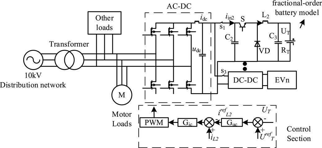
The structural model of the charging station in the article, as illustrated in Figure 1, primarily consists of the distribution network, transformer, PWM rectifier, DC-DC power converter, and electric vehicle load.
The transformer parameters are set at 10/0.4 kV, with the electric vehicle charging station having a maximum power of 120 kW. The input voltage is AC 380 V, the maximum output voltage is DC 750 V, and the maximum output current is 200 A. The DC-DC power converter employs a dual-loop control strategy comprising voltage and current loops. In this setup, where idc denotes the DC side current, udc stands for the DC side voltage, and iin2 refers to the capacitor current on the DC side, the voltage outer loop regulates the DC voltage udc with a reference value of urefdc, with the output of the voltage loop serving as the reference value irefdc for the current inner loop. The current inner loop controls the dq-axis tracking and generates control signals for the rectifier through PWM signal generation and dq inverse transformation.
2.1 Fractional calculus
Fractional calculus is a direct extension of integer-order calculus, and the theory and numerical computation of integer-order calculus form the basis for implementing fractional-order control. Here, α denotes the order of calculus, and the fractional differential operator is defined as follows (Mehta and Gupta, 2024):
There are several different definitions of fractional order calculus, including G-L, R-L, and Caputo definitions. In this study, the (G-L) definition method is chosen to represent the fractional differential operator of the fractional-order capacitor CPE:
Where Ts represents the sampling time interval, t denotes the current time instant, and j signifies the step number.
2.2 Small-signal model of fractional-order charging station systems
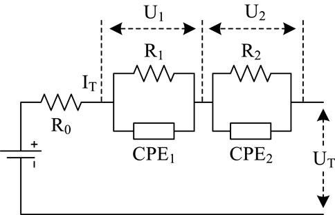
By combining electrochemical impedance spectroscopy (EIS) with fractional-order theory, a fractional-order impedance equivalent model is established, which outperforms integer-order models while overcoming the complexity of electrochemical model analysis (Liu et al., 2020). The paper selects a second-order RC equivalent circuit with fractional order to simulate energy storage units in lithium batteries for electric vehicles and charging stations. As shown in Figure 2, R0 represents the internal resistance of the lithium battery; R1 and R2 represent polarization internal resistances, and CPE represents the fractional-order capacitor. By combining the two polarized internal resistances and the fractional-order capacitor in parallel, the paper separately describes the electrochemical polarization process and the concentration polarization process of the lithium battery.
The CPE component in Figure 2, known as the Constant Phase Element, is represented by the impedance.
Applying Kirchhoff’s law, the fractional-order model in Figure 2 can be expressed as follows:
Where m and n represent the orders of the fractional capacitors CPE1 and CPE2 respectively; Qn is the maximum capacity of the current state of the lithium battery; Uoc represents the open-circuit voltage related to the SOC; IT is the total current of the battery pack; UT denotes the terminal voltage of the battery pack; U1 and U2 represent the voltages at the terminals of fractional capacitors CPE1 and CPE2 respectively.
In the process of parameter identification, it is necessary to discretize the differentiation terms of the model in Eq. 4 using the definition method introduced in Eq. 2. Due to the nonlinearity and multi-parameter nature of fractional-order batteries, a genetic algorithm is employed for model parameter identification. The fitness function of the algorithm aims to minimize the root mean square error of the model, as shown in the following equation:
Where N represents the length of the measured output voltage data yk, where yk is the measured output voltage, and ŷk denotes the estimated value. The genetic algorithm iterates with the objective of minimizing the mean square error to identify the battery parameters.
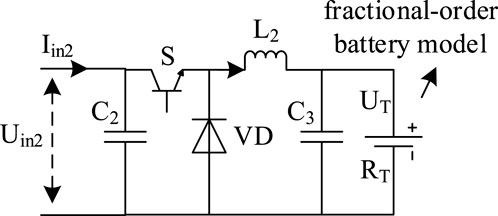
The fractional-order DC-DC converter circuit is depicted in Figure 3, where S represents the power switch, C denotes the fractional-order capacitor with order a (0 < a < 1), and L is the fractional-order inductor with order b (0 < b < 1).
The voltage-current relationship across the terminals of the fractional-order capacitor and the fractional-order inductor is given by:
Based on Figure 3 and the above analysis, the small-signal model of the fractional-order DC-DC converter can be obtained as:
where db represents the duty cycle, uT is the terminal voltage of the fractional-order battery, RT is the equivalent resistance of the battery, a and b represent the orders of the fractional-order capacitor and inductor respectively; Db is the equivalent duty cycle at the steady-state operating point of the DC-DC converter; Uin2 is the steady-state input voltage of the DC-DC converter; IL2 is the inductor current at the steady-state operating point. Transforming the small-signal model from the time domain to the frequency domain yield:
3 Optimization coordinated control method of virtual inertia based on fractional-order impedance model
3.1 Fractional-order PID controller
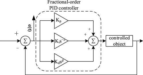
The system diagram of the fractional-order PID controller is depicted in Figure 4, with system parameters including the proportional gain Kp, integral gain Ki, derivative gain Kd, as well as the integral order α and derivative order β (Liu et al., 2024). The mathematical model of the fractional-order PID is given by:
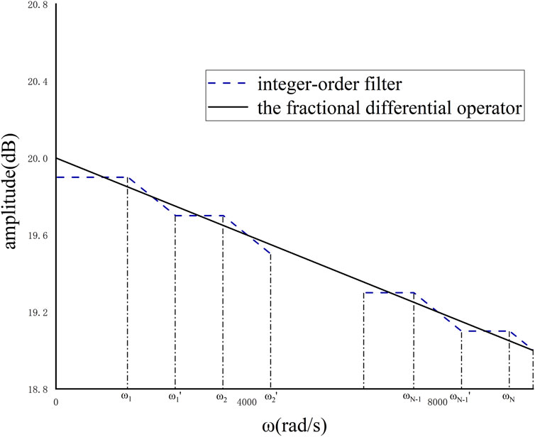
To guarantee optimal control performance, the utilization of integer-order approximation methods with suitable integer -order filters is indispensable. Two prevalent approaches for approximate implementation encompass continuous transfer function approximation and discretization. In accordance with the methodology advocated in reference (Zeng et al., 2022), the Oustaloup method is employed for accurately fitting the derivative operator through continuous transfer function approximation.
As shown in Figure 5, the Oustaloup method approximates the characteristics of fractional-order operators using a set of line segments. These line segments leverage the zeros and poles of integer-order filters to achieve alternating slopes of the magnitude-frequency response between 0 and -20 dB, enabling the approximation of fractional-order operators of any order. While integer-order PID controllers exhibit limited correction capabilities in the system’s frequency domain curve and poor overshoot suppression, fractional-order PID controllers offer flexible phase angles and different gain crossover frequencies, providing stronger correction abilities for frequency domain curves.
3.2 Virtual inertia control strategy based on fractional -order charging station model
According to the reference (Zhang et al., 2022), inertia in a DC system primarily originates from two sources: the DC motor and the DC capacitor. The virtual DC motor method enhances system stability by introducing virtual rotational inertia to simulate the DC motor and the DC capacitor. The relationship between torque and power is given by:
where Pm and Pe represent the virtual input mechanical power and output power, respectively. Dd stands for the damping coefficient, J denotes the virtual rotational inertia, and ωn is the rated angular rotor speed. The virtual synchronous machine incorporates inertia into the grid in the form of electrical power. When disturbances occur in the system load, the rotor achieves torque balance by releasing kinetic energy. Analogous to the aforementioned analysis, the paper considers enhancing system inertia by introducing a virtual capacitor that provides injected current, thereby achieving inertial support. Based on the fractional-order definition introduced in Eq. 2, where b represents the order of the capacitor, the port characteristics of the DC capacitor can be expressed as follows:
Based on the preceding analysis and in conjunction with Eqs 12, 13, the expression for the virtual inertia control of a fractional-order capacitor can be derived, as follows:
where iref represents the set current, uout denotes the output voltage value, and Ud stands for the rated output voltage. From the analysis above, it is evident that when an electric vehicle undergoes switching actions causing fluctuations, the DC capacitor rapidly emulates the output current to enhance the inertia of the charging station system, thereby preventing significant voltage fluctuations. The damping coefficient Dd signifies the amount of active power change in the output when the voltage changes significantly within a unit of time. A higher damping coefficient results in a faster restoration of the DC voltage.
The article analogizes the Buck circuit containing a fractional-order capacitor to a DC motor model. The control strategy of the system is illustrated in Figure 6, where it can be observed that the inertia of the system is influenced by the fractional-order capacitor, the inertia coefficient J, the damping coefficient D, as well as the parameters of the FOPID controller.
The adaptive virtual inertia control is expressed as follows:
where J0 as the virtual inertia coefficient at steady state, with kJ as the adjustment factor, and ku represents the voltage rate of change action thresholds.
In order to explore the correlation between the impedance model and the inertia coefficient, additional research is conducted utilizing the small-signal DC-DC model outlined in Eqs 9, 10. With reference to the control block diagram depicted in Figure 6, the small-signal model of the control equations can be derived as follows:
where uref represents the output voltage disturbance controlled by virtual inertia and damping coefficients. Here,
where kpu, kiu and kdu stand for the PID parameters of the outer voltage loop, while kpi, kii and kdi represent the PID parameters of the inner current loop. From Eq. 17, the relationship between uin2 and iL2, and other disturbance quantities can be derived as follows:
Finally, based on Eqs 9, 10, 18, the input impedance function of the DC-DC converter can be deduced:
4 Optimal parameter tuning for fractional-order controller
4.1 Particle swarm optimization-based FOPID parameter tuning method
The article focuses on optimizing the controller parameters of a DC-DC power converter using particle swarm optimization. When the charging process of electric vehicles is affected by the switching actions of the electric vehicle, it ensures that the system has sufficient inertia to maintain voltage stability. This enables electric vehicles to achieve stable charging and reduces the impact of external interference on the charging process.
Initially, the optimization objective is set to minimize the error between the impedance spectrum calculated using the actual measured impedance spectrum and the impedance model obtained from the Eq. 19. The five dimensions considered for particles include Kp, Ki, Kd, α and β. The velocity and position of particle p in the (k+1)th iteration are updated according to the following equation (Yang et al., 2019):
where Vin and Xin represent the velocity and position of the ith particle. Here, 1 ≤ n ≤ N, where N is the number of dimensions in the search space. "w" denotes the inertia weight, while c1 and c2 are positive acceleration coefficients. The variables r1 and r2 are two independent random numbers with values ranging from 0 to 1. The terms c1r1 and c2r2 control the movement speed of the particle swarm. Pin represents the current best position of the ith particle, while Pgn denotes the current best position of the particle swarm as a whole.
To ensure that the particle swarm converges towards the global optimum, an adaptive update is performed on the particle swarm in each iteration. The particles are sorted in descending order of fitness, and the 20% of particles with lower fitness values are selected for position and velocity initialization. This strategy increases the diversity of the population and prevents the particle swarm algorithm from getting stuck in local optima. The update in each iteration is achieved by assigning inertia weights based on the fitness value ranking of particles from large to small. The calculation equation for the inertia weight is as follows:
where ww(i) represents the fitness-based ranking of particle i, and "Num" is the size of the particle swarm. This improvement replaces the standard method of assigning values based on the number of iterations with inertia weights related to particle fitness values. It enhances global search capabilities and effectively prevents the particle swarm algorithm from converging to local optima.
By measuring the input DC voltage (udc′) and current (idc′) of the DC-DC converter, actual impedance data is obtained. Processing the measured impedance and impedance model output values using fractional Fourier transformation yields the impedance measurement spectrum in the frequency domain on the DC side:
The symbol frft represents the fractional Fourier transform operation, and γ denotes the order of the fractional Fourier transform. The impedance spectrum function itself is represented in the frequency domain, while the moment of inertia is represented in the time domain. The characteristic feature of the fractional Fourier transform is its ability to effectively combine time-domain signals and frequency-domain signals through arbitrary-order rotation. Essentially, the fractional Fourier transform is a time-frequency analysis method, representing all information of a signal from the time domain to the frequency domain in the fractional Fourier domain, reflecting more diverse local characteristics of the signal. The pth order Fourier transform can be expressed as:
where Kp represents the kernel function of the fractional Fourier transform.
By employing a step size of 0.01, the calculation of Eq. 22 is conducted for the parameter γ within the range of (0, 2). The maximum amplitude value M resulting from the fractional Fourier transform computation is identified to determine the optimal fractional order denoted as γ0. Subsequently, under this optimal order, M1 = xi + jyi is assigned to the measured impedance spectrum value, while the theoretically derived impedance spectrum value is denoted as M2 = xj + jyj. The resolution f = fs/N of the Fractional Fourier Transform (FRFT) is utilized as the incremental step size. The variable N represents the total count of data points collected, with each point reflecting the disparity between the modeled and actual values at the corresponding frequency. Based on the comprehensive analysis presented above, the constraints governing impedance spectrum deviation and voltage bias are established:
The e(ω) in the aforementioned equation is calculated using the following Eq. 26:
where imax represents the maximum iteration count, e(t) represents the deviation of the output quantity, i.e., the deviation between the output voltage and the actual reference voltage. It is known that the value of J should not be too large, otherwise it will lead to a long system recovery time and a decrease in the output power capacity of power electronic devices. Therefore, in order to maximize the inertia of the system, it is proposed to use the maximum virtual inertia as the objective function:
When disturbances cause the rate of change in voltage to exceed a threshold, the signal in the above equation is sampled at an update interval of 10 ms. The total number of points collected within one measurement interval is denoted as N.
4.2 Steps of fractional-order virtual inertia optimization control method
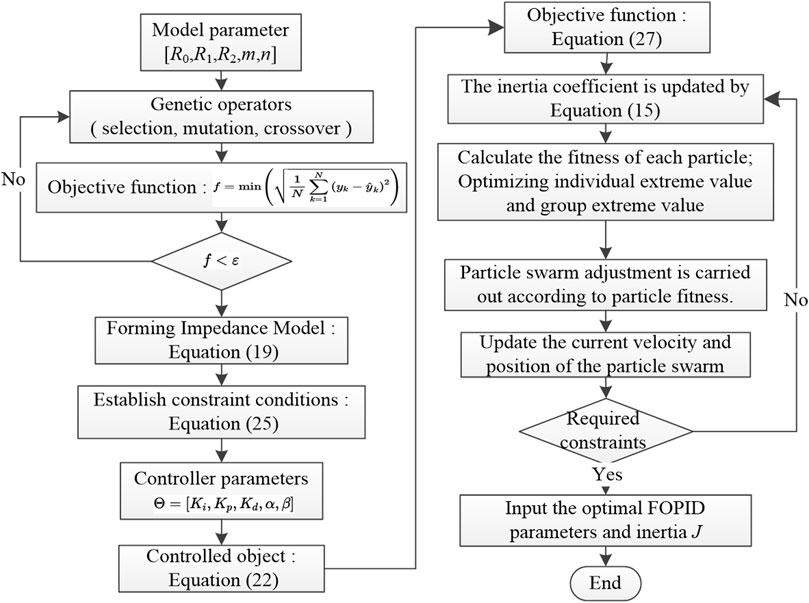
The study introduces a virtual inertia optimization control method based on the fractional-order impedance model of the charging station, with its algorithmic process depicted in Figure 7.
The steps of the algorithm are as follows.
(1) Define the parameters of the electric vehicle power battery [R0, R1, R2, m, n]. Utilize a genetic algorithm to iteratively calculate the objective function, which is expressed in Eq. 5.
(2) If the objective function meets the error standard, output the result and proceed to the next calculation. Otherwise, return to step 1 and perform iterative calculations again.
(3) When disturbances occur in the charging station system, such as switching of electric vehicles, the system experiences voltage mutation and generates voltage and power oscillations with gradually diminishing amplitude, causing the rate and magnitude of voltage changes to exceed the threshold. At this point, update the coefficients of the virtual inertia according to Eq. 15.
(4) Measure and calculate the maximum inertia under the current operating conditions with an update interval of 10 ms based on Eq. 27
(5) Use the current maximum inertia as the target and return to Step 3 for iterative calculation. Proceed to the next calculation when the voltage rate change meets the requirements.
(6) Set Eq. 25 as the target for virtual inertia control, and optimize the parameters of the FOPID controller using an improved particle swarm algorithm.
(7) Initialize the particle swarm, including the swarm size, search space range, inertia weight, acceleration coefficients, maximum iteration count, and particle velocity and position.
(8) Update the impedance function represented by Eq. 19 and compute the fitness function value of each particle according to Eq. 20.
(9) If the end condition is satisfied, output the optimal FOPID control parameters and moment of inertia J, and exit. Otherwise, return to step 7 for iterative recalculations until the result satisfies the termination condition.
5 Simulation results
5.1 Case data
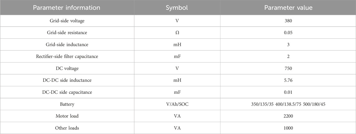
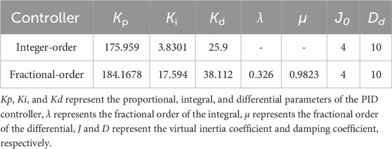
The article conducted simulation experiments using the charging station model illustrated in Figure 1, with the operational parameters of the system as outlined in Table 2.
5.2 Performance of control method
The simulation results illustrating the unit step response under two controllers using the impedance model presented in Eq. 19 as the controlled object are presented in Figure 8. It is evident from the figure that the system displays a rapid dynamic response, with a steady-state error of less than 0.3% and a relatively minor overshoot. These observations serve to validate the superior dynamic response performance of the fractional-order PID controller proposed in the article when compared to the integer-order controller.
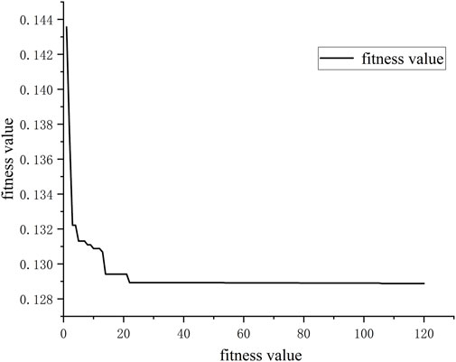
Experimental validation of the proposed fractional-order PID parameter tuning method was conducted, and fitness values were obtained. As depicted in Figure 9, it is evident that the improved particle swarm algorithm proposed in the article for parameter tuning exhibits low fitness values and converges after more than 30 iterations, indicating a favorable convergence speed.
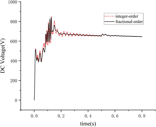
Considering a standalone operation in the system as shown in Figure 1, the operating conditions during a single bus switching, where switches s2 and s3 remain open while switch s1 is closed. From Figure 10, it is observed that when the electric vehicle is put on charge, the voltage offset amplitude for the integer-order controller is 826 V with a dynamic response time of 0.21053s. For the fractional-order controller, the voltage offset amplitude is 812 V with a response time of 0.025s. Upon reaching 0.5s, switch s1 is opened to terminate the electric vehicle’s charging process. During the disconnection phase, the dynamic response time for the integer-order controller is 0.000812s, whereas for the fractional-order controller, it is 0.000792s.
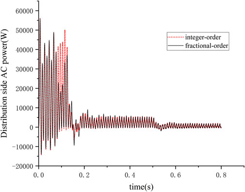
When a single electric vehicle is switched, power measurements are conducted on the other loads containing the electric motor load and the common connection point of the charging station on the distribution network side, as shown in Figure 11. The simulation results indicate that under the operational state of a single vehicle switch, the fractional-order control method utilized in the paper exhibits superior dynamic response capabilities compared to the integer-order control method.
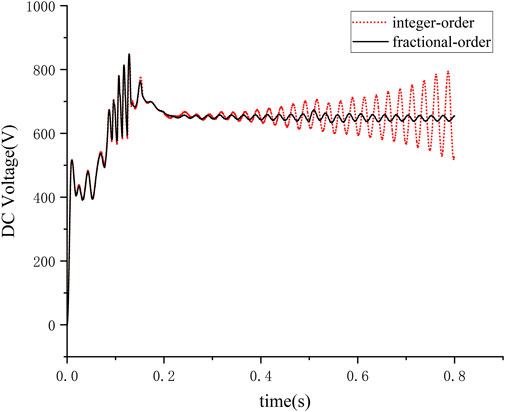
In the system depicted in Figure 1, multiple electric vehicles are considered for disconnection, with the parameters of the electric vehicles outlined in Table 3. The operational scenario is as follows: at the initial time, switches s1 and s2 are closed. At 0.2 s, switch s3 is closed to connect electric vehicle three to the charging station, and at 0.5 s, switch s1 is opened to stop the operation of electric vehicle 1. As shown in Figure 12, connecting three electric vehicles for charging at 0.2s results in minimal offset for the fractional-order controller under this operating condition. At 0.5s, when switch s1 is opened for operation, the integer-order controller exhibits significant DC voltage fluctuations, whereas the fractional-order controller demonstrates shorter dynamic response times, minimal voltage offsets, and ensures stable charging processes.
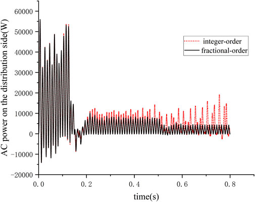
The power measurements for the system, including the electric motor load, other loads, and the common connection point of the charging station on the distribution network side, are depicted in Figure 13. When multiple charging stations are being switched, the fractional-order control method demonstrates a faster response speed, promptly providing sufficient inertia support for the system. Under this operating condition, the control method proposed in the paper exhibits superior performance in mitigating voltage and distribution-side power fluctuations compared to the integer-order method.
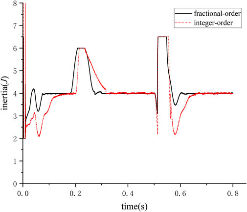
In Figure 14, the waveform depicts the variation in rotational inertia when multiple electric vehicles are being switched. The rotational inertia rapidly increases within 0.05 s to meet the maximum value specified in Eq. 27 when switching disturbances occur. Combining the simulation results mentioned above, it is evident that the method proposed in the paper effectively provides inertia support for the system when facing frequent short-term switching of electric vehicle loads. This method helps to mitigate DC voltage fluctuations and distribution-side power fluctuations, ensuring the stable operation of the system.
6 Conclusion
With the rapid development of electric vehicles, this study proposes a virtual inertia control strategy based on a fractional-order impedance model with FOPID control to enhance the system’s inertia support ability. The performance of single and multiple charging stations under different load switching conditions is compared through simulation. The following conclusions are as follows.
(1) This study introduces the fractional calculus theory and establishes a fractional-order impedance model for charging stations. Compared with traditional integer-order methods, the fractional-order modeling method reduces modeling errors since actual capacitance and inductance are fractional-order. This method is particularly effective for electric vehicle power batteries and charging station rectifiers with rich power electronic components, improving model accuracy and providing reliable model support for charging station control algorithm research.
(2) This paper employs a fractional-order controller to control the charging station system. Compared with integer-order controllers, fractional-order controllers have more adjustable parameters and a larger adjustable range, making the controller more flexible and able to achieve better control results. The simulation results show that using a fractional-order controller on top of the fractional-order impedance model of the charging station can control the dynamic response time within 0.025s and the DC voltage deviation within 5%, achieving better control results.
(3) Based on the fractional-order impedance model, a virtual inertia control optimization method is proposed with the fractional-order charging station impedance spectrum deviation as the objective function. When frequent switching actions occur at electric vehicle charging stations, this method can provide sufficient inertia support quickly and effectively. The simulation results show that this method can effectively suppress the DC voltage fluctuation of the charging station system and the power fluctuation of the network side during the oscillation process and can quickly provide sufficient inertia support for the system within 0.05 to ensure stable operation.
Data availability statement
The original contributions presented in the study are included in the article/Supplementary Material, further inquiries can be directed to the corresponding author.
Author contributions
JL: Writing–original draft, Funding acquisition, Methodology, Project administration, Resources, Supervision, Writing–review and editing. JH: Writing–original draft, Writing–review and editing, Conceptualization, Data curation, Formal Analysis, Software. BL: Writing–review and editing, Conceptualization, Formal Analysis, Project administration, Supervision, Validation.
Funding
The author(s) declare that no financial support was received for the research, authorship, and/or publication of this article.
Conflict of interest
The authors declare that the research was conducted in the absence of any commercial or financial relationships that could be construed as a potential conflict of interest.
Publisher’s note
All claims expressed in this article are solely those of the authors and do not necessarily represent those of their affiliated organizations, or those of the publisher, the editors and the reviewers. Any product that may be evaluated in this article, or claim that may be made by its manufacturer, is not guaranteed or endorsed by the publisher.
Supplementary material
The Supplementary Material for this article can be found online at: https://www.frontiersin.org/articles/10.3389/fenrg.2024.1404386/full#supplementary-material
Abbreviations
CPE, Constant Phase Elements; EV, Electric Vehicles; FO, Fractional-order; FOPID, Fractional-order PID; EIS, Electrochemical Impedance Spectroscopy; G-L, Grünwald-Letnikov; IO, Integer-order; ITAE, Integral of Time multiplied by Absolute Error; Particle Swarm Optimization, (PSO); Plug-In Electric Vehicle, (PEV); R-L, Riemann-Liouville; SOC, State of Charge.
References
Chen, Z., Zhang, Y., Yang, R., Liu, C., and Chen, G. (2024). Online internal temperature estimation for lithium-ion batteries using the suppressed second-harmonic current in single- phase DC/AC converters. IEEE Trans. Power Electron. 71, 9757–9766. doi:10.1109/tie.2023.3331090
Chuang, L. I. U., Yan, ZHANG, Zhu, Di, et al. (2021). Medium and low-voltage DC distribution system: impedance modeling and stability analysis of the key equipment. High. Volt. Eng. 47 (11), 3968–3983. doi:10.13336/j.1003-6520.hve.20201749
Gong, R., and Gu, J. (2023). Adaptive control strategy of inertia and damping for load virtual synchronous machine. Electr. Meas. Instrum. 60 (03), 130–135. doi:10.19753/j.issn1001-1390.2023.03.019
Guo, L., Zheng, M., Yanyan, L. I., et al. (2022). Nonparametric sliding mode predictive control strategy for a three-phase LCL grid-connected inverter. Power Syst. Prot. Control 50 (18), 72–82. doi:10.19783/j.cnki.pspc.211576
Hou, M., Zhao, Y., and Xinglai, G. E. (2017). Optimal scheduling of the plug-in electric vehicles aggregator energy and regulation services based on grid to vehicle. Int. Trans. Electr. Energ Syst. 27, e2364. doi:10.1002/etep.2364
Jing, L. I., Yan, YANG, Jianxin, Q. I. N., et al. (2020). Research on fractional modeling and state of charge estimation of lithium battery. Power Technol. 44, 983–985.
Jinhao, LIANG, Jiwei, FENG, Liang, F., Lu, Y., Yin, G., Mao, X., et al. (2023). An energy-oriented torque-vector control framework for distributed drive electric vehicles. IEEE Trans. Transp. Electrification 9 (3), 4014–4031. doi:10.1109/tte.2022.3231933
Jinyuan, L. I. U., Lin, L. Y. U., Gao, H., et al. (2020). Planning of active distribution network considering characteristics of distributed generator and electric vehicle. Automation Electr. Power Syst. 44 (12), 41–49.
Junfu, L. I., Wang, L., Lyu, C., and Pecht, M. (2017). State of charge estimation based on a simplified electrochemical model for a single LiCoO2 battery and battery pack. Energy 133, 572–583. doi:10.1016/j.energy.2017.05.158
Liao, X., Wang, Y., Donghui, Y. U., Ran, M., and Ruan, P. (2023). Modeling and analysis of Buck-Boost converter with non-singular fractional derivatives. Chaos Solit. Fractals 169, 113336. doi:10.1016/j.chaos.2023.113336
Linbin, HUANG, Huanhai, X. I. N., Wang, Z., Wu, K., Hu, J., et al. (2017). A virtual synchronous control for voltage-source converters utilizing dynamics of DC-link capacitor to realize self-synchronization. IEEE J. Emerg. Sel. Top. POWER Electron. 5 (4), 1565–1577. doi:10.1109/jestpe.2017.2740424
Lingling, X. I. E., Liu, L. U., and Bin, L. I. U. (2022). Research on fractional-order PIλDμ control of grid-connected inverter based on MPSO algorithm. Electr. Meas. Instrum. 59 (6), 172–180. doi:10.19753/j.issn1001-1390.2022.06.024
Liu, L., Lin, G., Jiao, S., et al. (2020). Virtual DC generator control strategy and its dynamic analysis of DC charging station microgrid. Power Syst. Prot. Control 48 (11), 28–35. doi:10.19783/j.cnki.pspc.190776
Liu, S., Sun, H., Haotong, Y. U., Miao, J., Zheng, C., and Zhang, X. (2024). A fractional order model of auxiliary power batteries suitable for hydrogen fuel cell hybrid systems heavy-duty trucks. Int. J. Hydrogen Energy 63, 346–358. doi:10.1016/j.ijhydene.2024.03.095
Lu, Li, Wu, W., Gao, Y., Yu, X., Zhang, C., et al. (2022). Study on current discrepancy and redistribution of HTS non-insulation closed-loop coils during charging/discharging and subsequent transient process toward steady-state operation. Supercond. Sci. Technol. 35 (9), 095001. doi:10.1088/1361-6668/ac7dfe
Macioszek, E. E-Mobility infrastructure in the górnolsko - zagbiowska metropolis, Poland, and potential for development the 5th world congress on new technologies.2019.
Macioszek, E. (2021). Analysis of trends in development of electromobility in Poland: current problems and issues. Transp. Dev. Challenges 21st Century, 145–156. doi:10.1007/978-3-030-50010-8_13
Macioszek, E., Cieśla, M., and Granà, A. (2023). Future development of an energy-efficient electric scooter sharing system based on a stakeholder analysis method. Energies 16 (554), 554. doi:10.3390/en16010554
Mehta, R., and Gupta, A. (2024). Mathematical modelling of electrochemical, thermal and degradation processes in lithium-ion cells—a comprehensive review. Renew. Sustain. Energy Rev. 192, 114264. doi:10.1016/j.rser.2023.114264
Pengcheng, Z. H. A., Yali, G. A. N., Gao, H., et al. (2022). Quality assessment of electric vehicle charging stations accessing distribution network. Electr. Meas. Instrum. 59 (06), 69–75. doi:10.19753/j.issn1001-1390.2022.06.010
Wang, H., Nie, J., Bin, L. I., et al. (2023). Fractional order sliding mode control strategy of AC/DC hybrid microgrid interconnection interface converter under grid voltage imbalance. Power Syst. Prot. Control 51 (16), 94–103. doi:10.19783/j.cnki.pspc.230421
Xiao, ZHANG, Zhou, K., and Fan, W. U. (2020). MMC grid-connected control strategy based on fractional order PI∼λ. Electr. Meas. Instrum. 57 (18), 115–121. doi:10.19753/j.issn1001-1390.2020.18.019
Xiaocong, L. I., Hou, L., Xueli, L. U. O., et al. (2023). Research on fractional modeling and controller design of three-phase inverter grid-connected system. Acta Energiae Solaris Sin. 44 (3), 415–424. doi:10.19912/j.0254-0096.tynxb.2021-1187
Yang, Y., Mei, F., Zhang, C., et al. (2019). Coordinated adaptive control strategy of rotational inertia and damping coefficient for virtual synchronous generator. Electr. Power Autom. Equip. 39 (3), 125–131. doi:10.16081/j.issn.1006-6047.2019.03.020
Yuan, L., Chen, Y., Tang, H., Ren, G., and Wenhuan, W. (2023). DGNet: an adaptive lightweight defect detection model for new energy vehicle battery current collector. IEEE Sensors J. 23 (23), 29815–29830. doi:10.1109/jsen.2023.3324441
Zeng, G., Liao, H., Zhao, J., et al. (2022). A self-adaptive control strategy of virtual inertia and a damping coefficient for bidirectional DC-DC converters in a DC microgrid. Power Syst. Prot. Control 50 (06), 65–73. doi:10.19783/j.cnki.pspc.210815
Zhang, Bo, and Xujian, S. H. U. (2022). Fractional-order electrical circuit theory. Singapore: Springer.
Zhang, X., Wang, Y., Yuan, X., Shen, Y., and Lu, Z. (2023). Adaptive dynamic surface control with disturbance observers for battery/supercapacitor-based hybrid energy sources in electric vehicles. IEEE Trans. Transp. Electrification 9 (4), 5165–5181. doi:10.1109/tte.2022.3194034
Zhang, X., Wang, Z., and Lu, Z. (2022). Multi-objective load dispatch for microgrid with electric vehicles using modified gravitational search and particle swarm optimization algorithm. Appl. Energy 306 (A), 118018. doi:10.1016/j.apenergy.2021.118018
Zhou, H., Wang, S., Chunmei, Y. U., Xia, L., and Fernandez, C. (2022). Research on SOC estimation for lithium-ion batteries based on improved PNGV equivalence model and AF-UKF algorithm. Int. J. Electrochem. Sci. 17 (8), 220836. doi:10.20964/2022.08.31
Zhou, W., Zheng, Y., Pan, Z., and Lu, Q. (2021). Review on the battery model and SOC estimation method. Processes 9 (1685), 1685. doi:10.3390/pr9091685
Keywords: inertia, fractional order PID(FOPID), electric vehicle charging station, fractional-order impedance modeling, energy research
Citation: Li J, Hu J and Liu B (2024) Optimized coordinated control method with virtual inertia based on fractional impedance model for charging stations. Front. Energy Res. 12:1404386. doi: 10.3389/fenrg.2024.1404386
Received: 21 March 2024; Accepted: 03 June 2024;
Published: 01 July 2024.
Edited by:
Xiao Wang, Wuhan University, ChinaReviewed by:
Elżbieta Macioszek, Silesian University of Technology, PolandMohamed Salem, University of Science Malaysia (USM), Malaysia
Copyright © 2024 Li, Hu and Liu. This is an open-access article distributed under the terms of the Creative Commons Attribution License (CC BY). The use, distribution or reproduction in other forums is permitted, provided the original author(s) and the copyright owner(s) are credited and that the original publication in this journal is cited, in accordance with accepted academic practice. No use, distribution or reproduction is permitted which does not comply with these terms.
*Correspondence: Jiang Li, bGlqaWFuZ19lZUBzaGllcC5lZHUuY24=
 Jiang Li
 Jianwei Hu
 Bo Liu