- 1DC Power Distribution and Consumption Technology Research Center of Guangdong Power Grid Co., Ltd., Zhuhai, China
- 2Zhuhai Power Supply Bureau of Guangdong Power Grid Co., Ltd., Zhuhai, China
- 3Electric Power Research Institute of China Southern Power Grid, Guangzhou, China
This paper introduces an improved decentralized control strategy for a photovoltaic (PV) hybrid energy storage (HES) system (HESS) in a DC microgrid. The power sharing method of the HES system is discussed in depth. The basic principle of virtual resistance and capacitance droop (VRCD) control, which consists of virtual resistance droop (VRD) and virtual capacitance droop (VCD) control, is analyzed in detail to achieve the decoupling of the HES system for high- and low-frequency load power distribution. For the virtual capacitance control loop, the voltage compensator is added to achieve terminal voltage restoration of the supercapacitor (SC). For the virtual resistance control loop, in order to solve the problems of the unbalanced state of charge (SOC) of battery storage, a virtual resistance droop control based on a novel adaptive function is introduced. Finally, a model of the HESS in a DC microgrid is built in a real-time emulator to verify the effectiveness of the proposed control strategy.
1 Introduction
With the development of new energy and power electronics technology, distributed energy sources such as wind and photovoltaic (PV) are connected to the DC distribution network (DC microgrid) through DC converters, which has become one of the current research hotspots. In recent years, the DC microgrid has been successfully applied in communication systems, ship systems, and green building fields. Compared to the AC microgrid, the DC microgrid has the following advantages: no problems of reactive power and phase synchronization, fewer power conversion stages, and higher device power density (Al-Ismail, 2024). To efficiently utilize the microgrid, the overall control strategy is a very important research topic. The control of the microgrid can be generally classified into centralized control and decentralized control. In the centralized control, each distributed unit receives the power set points from the central control unit through the communication network, which makes the microgrid encounter issues due to a single point of failure. In the decentralized control, the single-point-of-failure problem can be avoided, and the overall reliability of the microgrid is improved (Guerrero et al., 2011; Sechilariu et al., 2013; Valderrama-Blavi et al., 2013; Lu et al., 2014a; Lu et al., 2014b; Pan et al., 2022).
Conventional droop control is the most common decentralized control technique (Huang et al., 2011). The operating principle is to reduce the reference DC bus voltage with the increase in the output current of each unit. It is easy to implement. The disadvantages are that the current sharing accuracy is easily affected by line resistance, resulting in poor voltage regulation. To overcome the influence of line resistance, the virtual resistance-based droop control is proposed. A virtual resistance is included in the feedback loop of the output voltage control (Guerrero et al., 2011). However, it still encounters the problem of poor voltage regulation. Augustine et al. (2015) proposed an adaptive droop control based on instantaneous virtual resistance. The merits of minimizing the circulating current and current sharing differences can be achieved. The problem is that the interconnecting resistance between the converter and microgrid DC bus must be known in advance. An intelligent technique-based droop control is proposed by Diaz et al. (2014). A fuzzy logic technique is used to adjust the virtual resistance to reduce the voltage deviation of the microgrid DC voltage bus. However, the voltage deviation cannot be eliminated. Gu et al. (2014) introduced a mode-adaptive droop control for the PV–wind storage hybrid DC microgrid. The droop control mode or power control mode is employed with respect to different voltage ranges of the DC bus. The overload condition of the system can be avoided. The sensor accuracy and the voltage range selection are quite critical for the overall control.
Multiple techniques are proposed in the literature to improve the droop control. Kakigano et al. (2013) and Diaz et al. (2014) obtained the virtual resistance adjustment by inputting the bus voltage deviation signal to the fuzzy controller. However, when the system is to be extended, the affiliation function needs to be adjusted. Morstyn et al. (2018) proposed the dynamic average voltage and current consistency algorithm to correct the droop reference voltage in real-time. However, the convergence of the consistency algorithm is determined by the system communication topology, and the expansion of multiple intelligences will result in a longer convergence time. Yang et al. (2024) proposed an improved nonlinear droop control strategy, which uses the difference between the squared nominal voltage and the squared DC voltage as the droop input. A faster transient response is achieved. Sevostyanov and Gorbunov (2023) designed a droop-based frequency-selective impedance control for a regular droop-controlled DC converter to mitigate the voltage ripples in DC microgrids. Sharma et al. (2023) proposed a droop-based distributed control method for radial DC microgrid systems with reduced communication complexity. Lu et al. (2014c) achieved state-of-charge (SOC) balance by introducing a power function with SOC as a variable as an adaptive function to adjust the virtual resistance. However, compared with the constant virtual resistance, it has a larger charging current, which can cause battery energy storage overcharge problems.
This paper proposes a decentralized control strategy for a hybrid energy storage (HES) system for achieving the decoupling of the HES system for high- and low-frequency load power allocation, maintaining the DC bus voltage, and achieving SOC balance among the battery energy storage systems. The proposed control strategy includes virtual resistance and capacitance droop (VRCD) control, supercapacitor (SC) terminal voltage restoration, and improved SOC balancing control based on a novel adaptive function. First, the VRCD control extends the traditional droop control. The battery storage adopts virtual resistance droop (VRD) control, and the SC adopts virtual capacitance droop (VCD) control. Thus, the SC can quickly respond to the load power fluctuation, and the battery storage provides all the steady-state load power. Second, a voltage compensator is added in the VCD loop to achieve the terminal voltage restoration of the SC. Finally, a novel adaptive function is introduced in the virtual resistance control loop to achieve the SOC balance of the battery storage system and also avoid the overcharge and over-discharge of battery storages.
2 System architecture and control
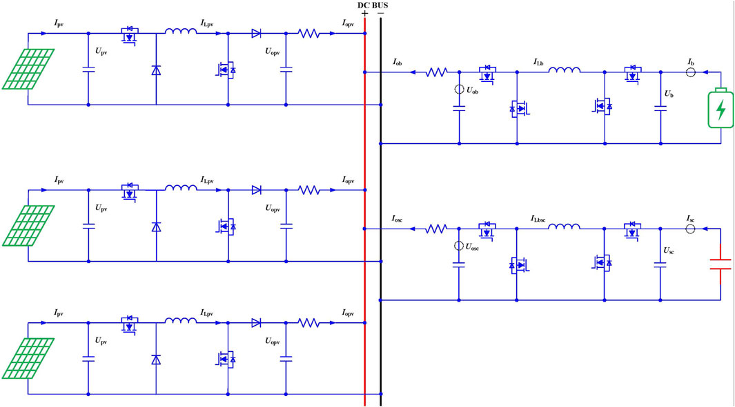
A typical low-voltage DC (LVDC) microgrid mainly consists of PV, HES system, and constant power load (CPL), as shown in Figure 1. In the structure, the HESS consists of a high-power density storage system like an SC and a high energy density storage system like a battery. The distributed renewable energy storage is PV. Each PV or HESS is connected to the DC bus through a DC/DC converter. The mainstream topology for the DC/DC converter of the PV and HESS currently is basic Buck or boost (including derived topologies such as interleaved Buck or boost). The existing DC/DC converters used in an LVDC microgrid have a common drawback: the conventional Buck or boost circuit topology severely limits the input voltage range, which can constrain the design of the distributed PV or HESS modules. However, the voltage of the distributed PV or HESS modules varies over a wide range, and a single Buck or boost topology cannot meet this demand. Generally, the input voltage for the PV string inverter is 200 V–1,100 V. On the other hand, there is currently no unified standard for the voltage level of LVDC microgrid systems. The voltage level of the LVDC is generally decided by the power capacity. For a low power capacity, the voltage of the LVDC microgrid system is in the range 300 V–400 V (typically 380 V). For the high power capacity, the voltage of the LVDC microgrid system is in the range 600 V–800 V (typically 750 V). In order to improve the equipment compatibility, a DC/DC converter capable of increasing or reducing the voltage at the same time is more promising. Compared with traditional reverse-polarity Buck–boost converters, dual-switch or four-switch Buck–boost converters have the same polarity in output and input. The voltage stress of each switching device is lower, making it convenient to choose the corresponding withstanding voltage-switching device. At the same time, in order to be compatible with most LVDC equipment and achieve a high efficiency output, the four-switch Buck–boost converter technology is adopted in the LVDC microgrid system architecture. If the LVDC microgrid is connected with the utility grid through the bidirectional inverter, the proposed control can still be effective if the bidirectional inverter cannot guarantee a constant DC bus voltage under all scenarios. In that case, the virtual capacitance droop control without voltage restoration can be applied to the bidirectional inverter while taking the utility grid as an infinite energy storage system.
3 Proposed control method
3.1 VRCD controller
The conventional droop control adopted to achieve load current sharing in the DC microgrid is given by the following equation (Zeng et al., 2021):
where Uout is the reference DC microgrid bus voltage, Uo is the output voltage of each distributed unit, R is the virtual resistance, and Iout is the output current. The droop control has been extended to the HES system, which is named as VRCD control. The equivalent circuit is shown in Figure 2.
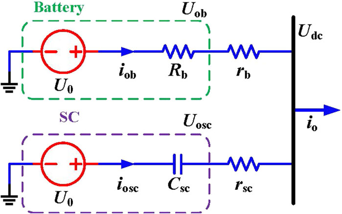
Figure 2. Equivalent circuit of the hybrid energy storage (HES) system employing the virtual resistance and capacitance droop (VRCD) control.
The virtual capacitor is equal to a short circuit responding to the high-frequency waveform and an open circuit responding to the low-frequency waveform. Thus, the role of a high-power density storage system (such as an SC) is to mitigate the high-frequency power without providing low-frequency power support.
The control equations of the VRCD for the HES system are as follows:
where U0 is the reference voltage of VRCD control and Uob and iob are the output voltage and current of the conditioning converter for the high-energy density storage (battery converter), respectively. Uosc and iosc are the output voltage and current of the conditioning converter for the high-power density storage (SC converter), respectively. io is the total output current of the HES system. Rb and Csc are the virtual resistance and virtual capacitance, respectively. If the line resistance is considered, the virtual resistance of the system will be increased, which will slow down the overall dynamic performance. To guarantee the designed dynamic performance, the virtual capacitance Csc can be reduced to compensate for the impact of the line resistance.
If the line resistances rb and rSC are neglected, the output current of each converter is calculated as
As shown in Eq. 3, Rb should be designed to be much larger than rSC to reduce the influence of rSC. In the actual design, the SC and its DC/DC converter should be placed as close as possible to the bus or be connected to the low-resistance wires. If rSC is not taken into consideration, GLPF*(s) and GHPF*(s) can be expressed in the standard form of a first-order low-pass filter and first-order high-pass filter.
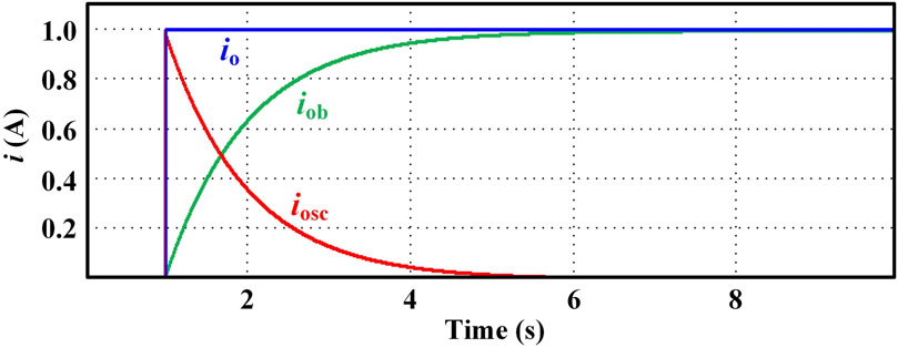
The response output current of the SC and battery converter corresponding to a unit step change in the output current io of the HES system is given in Figure 3. It can be found that the iosc of the SC converter follows the io step change instantaneously. This SC converter output current decreases to 0 progressively. Moreover, iob of the battery converter increases from 0 to io progressively.
3.2 Proposed adaptive virtual droop controller
A high-power density storage system like an SC is employed to compensate for the high-frequency power fluctuation owing to its fast dynamic feature. However, if the power of the SC converter flows uninterruptedly in the same direction, the voltage across the SC will increase or decrease quickly because of its low energy density. When the voltage of the SC changes into overcharge and over-discharge states, the SC stops working. This will have a negative effect over the SC because the power sharing technique of the transient power of the HES system will fail in that case. Therefore, it is essential to restore the terminal voltage of the SC during its operation.
The main function of the SC based on its I-V characteristics is as follows:
where C represents the capacitance of the SC. Usc is the voltage across the SC. isc is the discharge current value of the SC. To realize the voltage restoration of the SC, a voltage restoration loop is added in the VRCD controller, as shown in Figure 4.
The equation of the voltage restoration control is
where Usc and
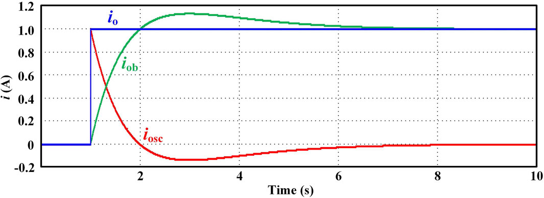
During the power compensation process of the transient power of the microgrid, the voltage across the SC is subject to variation. As shown in Figure 5, if Usc <
The response output current of the SC and battery converter corresponding to a unit step change in the output current io of the HES system is given in Figure 5. It can be found that the SC converter current iosc follows step change in io instantly. Later, the SC converter current iosc is gradually commutated to the battery output current iob. After iosc decreases to 0 and iob increases to io, iosc keeps decreasing in the negative direction and iob keeps increasing to a value higher than io. During this process, the SC discharges initially and restores the voltage later. At the end of the restoration process of the SC voltage, iosc and iob stabilize at the value of 0 and ios, respectively.
The high-energy density storage system like the battery in the HES system balances the system power under the steady-state condition in the microgrid. The virtual resistance Rb is decided by the battery capacity and designed ΔUmax. If the SOC is neglected, a constant value of Rb results in the overcharge or over-discharge of the battery storage system. The SOC unbalance of the battery will also be a problem. To overcome the above disadvantages, the virtual resistance Rb is proposed to be adaptively attuned according to the SOC of the battery storage system under the steady-state condition, as shown in Figure 6.
The SOC of the battery is the ratio of the rest charge to the overall charge. It can be generally calculated using the Coulomb counting method as shown in the following equation (Zhang et al., 2022):
where SOCi(t0) is the initial SOC and SOCi(ts) is the SOC at the time of ts. ibi presents the output current of the battery storage system. When ibi is positive, the battery storage discharges the energy. When ibi is negative, the battery storage charges the energy. Cei is the overall capacity of the ith battery storage system. Generally, the battery storage energy density is comparatively large, and the ratio of SOC variation can be considered quite slow.
Thus, the voltage across the battery storage system is assumed to be constant within a short time interval. If the loss of the bidirectional DC/DC interfacing the battery and dc bus is not taken into consideration, then,
Substituting Eq. 8 into Eq. 7 provides the following equation:
where ΔSOCi is the SOC variation of the ith battery energy storage system. Ubi represents the voltage across the ith battery energy storage. Uobi and iobi are the output voltage and output current of the ith battery DC/DC converter, respectively. Udc is the microgrid DC bus voltage.
Based on Eq. 9, the SOC variation of the battery storage system is influenced by the value of the interfacing DC/DC converter output current. To realize the SOC balance of the battery storage, the main control principle is that the battery with a higher SOC bears a larger proportion of current during the discharge procedure and a smaller proportion of current during the charging procedure.
The droop control equation of the SOC is given as
where
The trigonometric function is proposed as an adaptive function. The adaptive virtual resistance for both charge and discharge states can be calculated as
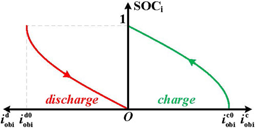
When iobi >0, sin (π·SOCi/2) increases monotonically with the value of SOCi. The battery with a higher value of the SOC will have a smaller virtual resistance, and its DC/DC converter output discharging current will be larger. When iobi <0, sin (π·SOCi/2+π/2) decreases monotonically with the value of SOCi. The battery with a lower value of the SOC will have a smaller virtual resistance, and its DC/DC converter input charging current will be larger as well.
Moreover, both sin (π·SOCi/2) and sin (π·SOCi/2+π/2) vary within the range of [0, 1]. During the process of the discharging and charging states, the following relationship is established:
It is worth noting that the adaptive virtual resistance is larger than the initial value for the same energy storage system. Thus, the current of the battery DC/DC converter decreases if the SOC impact is not included. It can be expressed by
where
The virtual capacitance of the HES system Csci can be calculated by the following equations with the proposed trigonometric function as an adaptive function:
where the natural frequency ωn and damping coefficient ξ are presented as
Based on Eqs 13, 14, the curves of the charging and discharging of the battery DC/DC converter currents with respect to their SOC are given in Figure 7. During the discharging process, the adaptive function of sin (π·SOCi/2) decreases with the decrease in the SOC. Moreover, the battery DC/DC converter discharging current reduces from
The charging and discharging currents of the battery DC/DC converter with respect to different values of the SOC are shown in Table 1. Here, the charging and discharging currents are normalized with
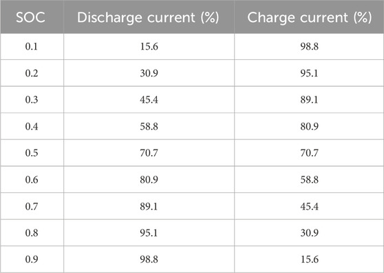
Table 1. Charging and discharging currents at different state-of-charge (SOC) typical values (standard values).
As shown in Table 1, the discharging current is high when the SOC is high in the discharging state. As the SOC decreases, the discharging current decreases faster. In the charging state, when the SOC is low, the charging current is large. As the SOC increases, the charging current decreases at an accelerated rate. Therefore, the proposed adaptive function can effectively suppress the charging and discharging currents in the undesirable SOC condition, while guaranteeing the power regulation capability of the battery storage system in the proper SOC condition.
4 Analysis of experimental results
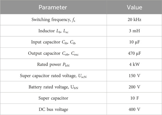
A DC microgrid simulation model, which consists of two PVs (MPPT), one HES, and a constant power load (CPL), has been established in order to examine the proposed control technology in this section. Experiments are conducted using a real-time emulator for hardware-in-the-loop (HIL) testing. The proposed control is achieved through I/O signals or communication. The closed-loop test of the device has low delay, high precision, and high degree of programming freedom, which can effectively simulate the actual operation. These real-time simulation experiments are tested over a StarSim MT6020 real-time emulator. Three different experiments have been conducted. Table 2 illustrates all related system parameters.
4.1 Experiment I: VRCD control
The work principle of VRCD control for the HES system is verified in this experiment. For an instance, as in the discharge mode, the rated power of the battery storage is 4 kW, and the maximum instantaneous power of the SC is 6 kW, while the maximum output power is 4 kW for PV1 and 3 kW for PV2.
The experimental results are shown in Figure 8A. The droop reference voltage is set as Uo = 390 V. The virtual resistance Rb = 2.7 Ω, the cutoff frequency fc = 0.2 Hz, and virtual capacitance Csc = 0.295 F.
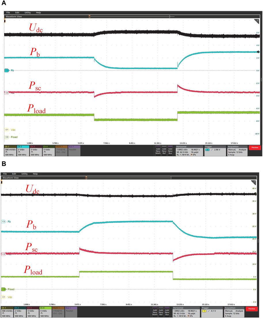
Figure 8. Experimental results of VRCD control (Vdc: 50 V/div, Pb: 2 kW/div, Psc: 5 kW/div, and Pload: 5 kW/div): (A) discharging mode; (B) charging mode.
Interval 1 (0–6.6 s): The total PV power is 7 kW, and the total load power is 9 kW. Udc is 378 V. The HES system is under a discharging situation with a battery discharge power of 2.08 kW and an SC output power of 0.4 kW.
Interval 2 (6.6–12.8 s): A sudden decrease to 7 kW can be observed on Pload when t = 6.6 s. Pload < Ppv+ Pb, which results in an increase in Udc. The SC charging power decreases from 1.8 kW to 0 slowly after an instant response, while the battery discharge power decreases from 2.08 kW to 0.4 kW. After 1.97 s, Udc is 388 V.
Interval 3 (12.8–17 s): A sudden increase to 10 kW can be observed on Pload when t = 12.8 s. Pload > Ppv+ Pb, which results in a reduction in Udc. The SC charging power decreases from 3 kW to 0.4 kW slowly after an instant response. The battery discharge power increases from 0.4 kW to 2.96 kW slowly. After 2.59 s, Udc is 372 V.
The decoupling power compensation for the high-/low-frequency load power of the HES system can be completed by the VRCD control, according to the experimental data. On this occasion, the high-frequency power variation can be balanced by rapid SC responses, while the output power of the SC remains nearly 0 under a stable state. A battery with high energy density maintains the power balance of the system under a stable state, while under a transient state, its output power makes mild changes.
The experimental results of VRCD control for the charging mode are given in Figure 8B. The droop reference voltage is set as Uo = 400 V. The virtual resistance Rb = 1.0 Ω, the cutoff frequency fc = 0.2 Hz, and virtual capacitance Csc = 0.796 F. Similarly, like the discharging mode, during the sudden change in load power, the SC immediately responds to maintain a constant DC bus voltage. Later, the battery will take over the power, and the SC power will reduce to 0 slowly. The experimental result given in Figure 8B shows that the decoupling power compensation for high-/low-frequency load power of the HES system can be achieved by the VRCD control under the charging mode as well.
4.2 Experiment II: terminal voltage restoration of the SC
Compared with experiment I, the virtual capacitance control loop in the conventional VRCD control is modified by adding a voltage compensator. In the discharging mode, Uo = 390 V, Rb = 2.7 Ω, fc = 0.4 Hz, and Csc = 0.164 F. The experimental results are shown in Figure 9A.
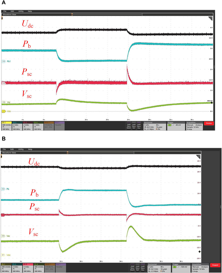
Figure 9. Terminal voltage restoration of SC (Udc: 50 V/div, Pb: 2 kW/div, Psc: 5 kW/div, Vsc: 1 V/div, and offset: 150 V): (A) discharging mode; (B) charging mode.
Interval 1 (0–10.35 s): The total PV power is 7 kW, and the total load power is 9 kW. Udc is 376 V. The voltage across the SC is 149.88 V. The HES system is under a discharging state with a battery discharge power of 2.08 kW and an SC output power of 0.16 kW.
Stage 2 (10.31–20.67 s): A decrease to 7 kW can be observed on Pload when t = 10 s. Pload < Ppv+ Pb, which results in an increase in Udc. During the first stage (10.35 s < t < 11.21 s), the SC charging power decreases from 2 kW to 0 slowly after an instant response, while the battery discharge power decreases from 2 kW to 0. The SC terminal voltage increases to a peak of 150.32 V. During the second stage (11.2 s < t < 20.67 s), by changing to the discharging state, the SC discharging power fluctuates, with an increase followed by a decrease. The SC terminal voltage decreases to 149.92 V smoothly, and Udc is 390 V.
Stage 3 (23.67–40 s): An increase to 10 kW can be observed on Pload when t = 23.67 s. Pload > Ppv+ Pb, which results in a reduction in Udc. During the first stage (23.67 s < t < 24.66 s), the SC charging power decreases from 3.2 kW to 0.08 kW after an instant response, while the battery discharge power increases from 0.16 kW to 3.28 kW step by step. The SC terminal voltage decreases to a minimum of 149.2 V. During the second stage (24.66 s < t < 40 s), by changing to the discharging state, the SC discharging power fluctuates, with an increase followed by a decrease. The SC terminal voltage increases to 149.96 V smoothly, and Udc is 368 V.
The experimental results for the charging mode are given in Figure 9B. In the charging mode, U0 = 400 V, Rb = 1.0 Ω, fc = 0.4 Hz, and Csc = 0.442 F. During the sudden change in load power, the SC immediately responds with the proposed VRCD control. Because of the charging or discharging of the SC, its voltage deviates from the rated value. With the terminal voltage restoration control added in the control loop, the voltage of the SC changes to the rated value slowly.
According to the experiment data, the terminal voltage of the SC can be restored in time in the transient process with the addition of a voltage compensator. The decoupled power compensation of the HES system with respect to the high/low frequency power of the load remains effective. The SC and battery storage responded to both instantaneous and stable situations.
4.3 Experiment III: SOC balance
The proposed triangle adaptive function has been applied in the virtual resistance control circuit for the operation of battery storage systems in parallel circuits. The capacities of B1 and B2 are set to 4 KW. The initial SOCs are 0.8 and 0.2, respectively. The output line resistance of the converter is rb1 = rb2 = 0.1 Ω. In the discharge mode, U0 = 390 V and Rb1 = Rb2 = 2.7 Ω. The experimental results are shown in Figure 10.
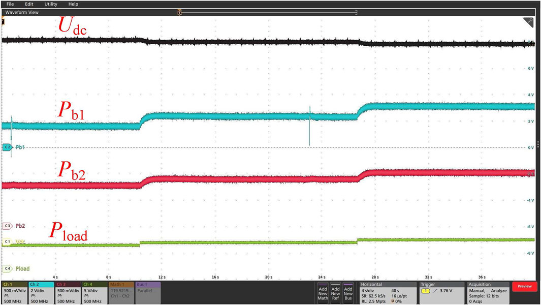
Figure 10. SOC balance of the Battery System Units (BSUs) (discharging mode) (Udc: 50 V/div, Pb1: 1 kW/div, Pb2: 1 kW/div, and Pload: 4 kW/div).
Interval 1 (5–20 s): Pload = 9 kW > Ppv = 7 kW, the battery storage systems are discharged. The discharge powers of B1 and B2 are 16,000 W and 760 W, respectively, and the ratio reaches 2.11:1. Udc is 384 V.
Interval 2 (20–35 s): An increase to 10 kW can be observed on Pload when t = 20 s. Udc decreases to 380 V. The discharging powers of B1 and B2 are 2,400 W and 900 W, respectively, and the ratio reaches 2.66:1.
Interval 3 (35–50 s): An increase to 11 kW can be observed on Pload when t = 35 s. Udc decreases to 376 V. The discharging powers of B1 and B2 are 3,120 W and 1,020 W, respectively, and the ratio reaches 3.06:1.
The above experimental result reveals that the discharging power ratio of B1 and B2 remains in a steady state, which is consistent with the parameters listed in Table 1. A decrease of around 2.95% in SOC1 and 0.99% in SOC2 can be observed at 50 s of discharging.
In the charging mode, the experimental results are shown in Figure 11. U0 = 400 V, and Rb1 = Rb2 = 1.0 Ω.
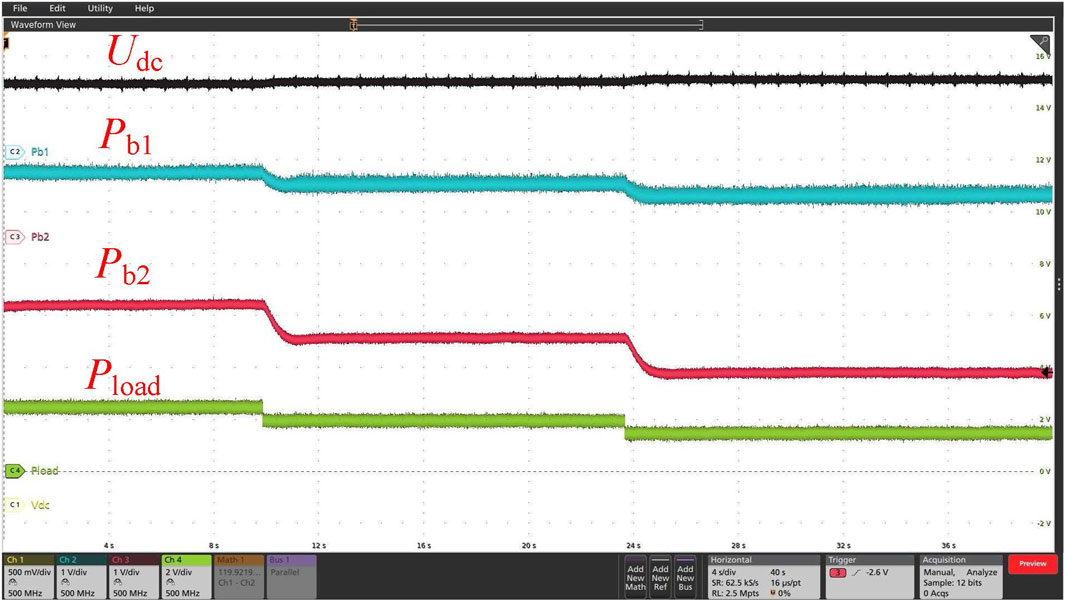
Figure 11. SOC balance of the BSUs (charging mode) (Vdc: 50 V/div, Pb1: 1 kW/div, Pb2: 1 kW/div, and Pload: 4 kW/div).
Interval 1 (5–20 s): Pload = 5 kW < Ppv = 7 kW, and the battery storage systems are charged. The charging powers of B1 and B2 are 400 W and 1,280 W, respectively, and the ratio reaches 1:3.2. Udc is 406 V.
Interval 2 (20–35 s): A decrease to 4 kW can be observed on Pload when t = 20 s, which results in an increase to 408 V on Udc. The charging powers of B1 and B2 are 600 W and 1,920 W, respectively, and the ratio reaches 1:3.2.
Interval 3 (35–50 s): A decrease to 3 kW can be observed on Pload when t = 35 s, which results in an increase to 410 V on Udc. The charging powers of B1 and B2 are 800 W and 2,600 W, respectively, and the ratio reaches 1:3.25.
The above experimental result reveals that the charging power ratio of B1 and B2 remains in a steady state, which is consistent with the parameters listed in Table 1. An increase of around 0.82% in SOC1 and 2.6% in SOC2 can be observed at 50 s of discharging.
The experiment illustrates that in the discharging process, the discharging power is negatively correlated with the SOC for the battery storage. In the charging process, the charging power is positively correlated with the SOC for the battery storage. The SOC difference from different battery storage systems becomes smaller during the experiment, which verified that the assumed adaptive function can maintain the SOC balance of battery storage systems.
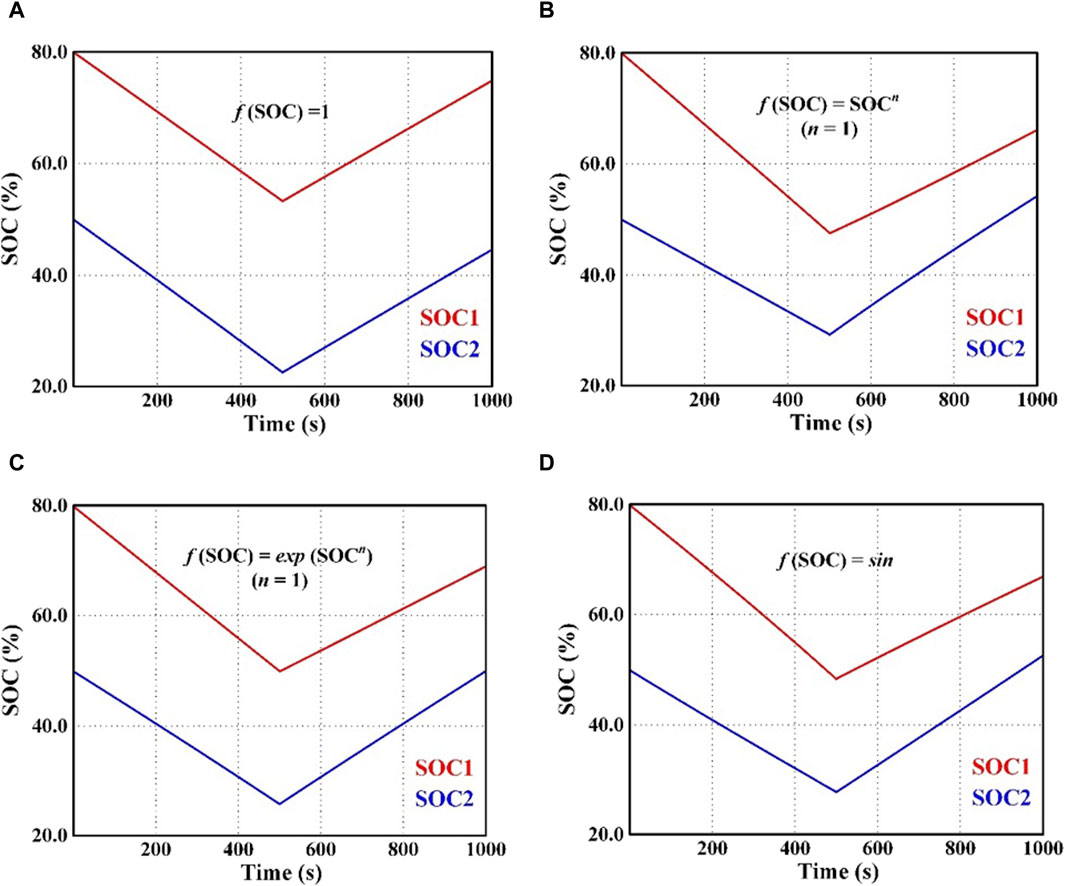
The initial SOCs of B1 and B2 are set to be 0.8 and 0.5, respectively; charging and discharging at 1,000 s have been conducted for battery storage systems in a parallel circuit. Between 0 and 500 s, Pload = 11 kW > Ppv = 7 kW, and the battery storage system discharges at a power of 4 kW. Between 500 and 1,000 s, Pload = 3 kW < Ppv = 7kW, and the battery storage systems are charged with a power of 4 kW. Different SOC balance effects by adopting different forms of adaptive functions are shown in Figure 12.
If a constant virtual resistance is adopted, the SOC difference between the battery energy storage systems remains constant during the whole charging and discharging process. Two existing adaptive functions, namely, the power exponential function and the power function, are introduced to compare with the proposed trigonometric function. The adaptive virtual resistance for both charge and discharge states for the power function can be calculated as
The adaptive virtual resistance for both charge and discharge states for the power exponential function can be calculated by
When different adaptive functions are introduced into the virtual resistance control for the battery storage systems, the SOC differences decrease steadily. Two existing adaptive functions and the proposed trigonometric function all achieve the SOC balance of the battery storage systems. However, considering the speed of the SOC balance, the proposed trigonometric adaptive function is much faster than the power exponential function and slightly slower than the power function form.
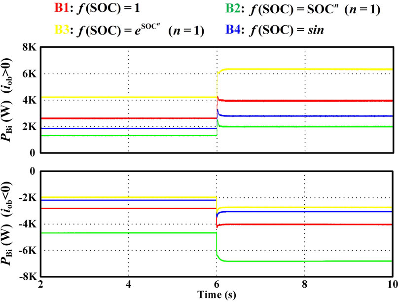
Further comparison of different forms of adaptive functions is carried out in terms of the output power under the same operating condition. For a battery with initial SOC = 0.5 and rated power of 4 kW, the output power when employing different adaptive functions is shown in Figure 13.
During the discharging process, PB3>PB1>PB4>PB2. It can be found that when the discharging power of B1 reaches 4 kW, the discharging power of B3 is higher than 6 kW. Under this condition, the battery storage is easily over-discharged by adopting the power exponential function. However, the discharging current of the proposed trigonometric adaptive function is smaller. It is advantageous to the battery storage operation. During the charging process, PB2>PB1>PB4>PB3. It can be found that when the charging power of B1 reaches 4 kW, the charging power of B2 is almost 7 kW. In this case, the battery storage is easily over-charged by adopting the power function. However, the charging current of the proposed trigonometric adaptive function is smaller. It is advantageous to the battery storage operation as well. It can be concluded that the proposed novel adaptive function can solve the overcharge and over-discharge issues of the battery energy storage system, which is consistent with conclusion obtained from the theoretical analysis.
5 Conclusion
For the energy storage devices in a DC microgrid, battery energy storage has high energy density but a slow dynamic response. The SC has a fast dynamic response but small energy density. This paper proposes a decentralized control strategy for the HES system, which can achieve the decoupling power compensation for high- and low-frequency load power distribution. For the problems of SOC unbalance, uneven load current sharing, and fast terminal voltage change in the SC, this paper proposes a decentralized control strategy with SC terminal voltage restoration and virtual resistive and capacitance droop control based on a novel adaptive function. It can achieve dynamic SOC balance and accurate load current sharing. Furthermore, the experimental results show that the proposed control strategy has better SOC convergence performance and can better avoid the energy storage overcharge and over-discharge problems compared with the traditional control strategy.
Data availability statement
The raw data supporting the conclusion of this article will be made available by the authors, without undue reservation.
Author contributions
JL: conceptualization, funding acquisition, methodology, project administration, writing–original draft, and writing–review and editing. YC: supervision, writing–original draft, and writing–review and editing. YW: conceptualization, methodology, and writing–original draft. XC: formal analysis, validation, visualization, and writing–review and editing. RY: investigation, software, and writing–review and editing.
Funding
The author(s) declare that financial support was received for the research, authorship, and/or publication of this article. This research was funded by the R&D Project of China Southern Power Grid Co., Ltd, grant number No. 030400KK52220005/GDKJXM20220237. The funder was not involved in the study design, collection, analysis, interpretation of data, the writing of this article, or the decision to submit it for publication.
Conflict of interest
Authors JL, YC, XC, and RY were employed by the DC Power Distribution and Consumption Technology Research Center of Guangdong Power Grid Co., Ltd.
Authors JL, YC, XC, and RY were employed by the Zhuhai Power Supply Bureau of Guangdong Power Grid Co., Ltd.
Author YW was employed by the Electric Power Research Institute of China Southern Power Grid.
Publisher’s note
All claims expressed in this article are solely those of the authors and do not necessarily represent those of their affiliated organizations, or those of the publisher, the editors, and the reviewers. Any product that may be evaluated in this article, or claim that may be made by its manufacturer, is not guaranteed or endorsed by the publisher.
References
Al-Ismail, F. S. (2024). A critical review on DC microgrids voltage control and power management. IEEE Access 12, 30345–30361. doi:10.1109/access.2024.3369609
Augustine, S., Mishra, M. K., and Lakshminarasamma, N. (2015). Adaptive droop control strategy for load sharing and circulating current minimization in low-voltage standalone DC microgrid. IEEE Trans. Sustain. Energy. 6 (1), 132–141. doi:10.1109/tste.2014.2360628
Diaz, N. L., Dragiˇcevi´c, T., Vasquez, J. C., and Guerrero, J. M. (2014). Intelligent distributed generation and storage units for DC microgrids— a new concept on cooperative control without communications beyond droop control. IEEE Trans. Smart Grid. 5 (5), 2476–2485. doi:10.1109/tsg.2014.2341740
Gu, Y., Xiang, X., Li, W., and He, X. (2014). Mode-adaptive decentralized control for renewable DC microgrid with enhanced reliability and flexibility. IEEE Trans. Power Electron. 29 (9), 5072–5080. doi:10.1109/tpel.2013.2294204
Guerrero, J. M., Vasquez, J. C., Matas, J., de Vicuna, L. G., and Castilla, M. (2011). Hierarchical control of droop-controlled AC and DC microgrids—a general approach toward standardization. IEEE Trans. Ind. Electron. 58 (1), 158–172. doi:10.1109/tie.2010.2066534
Huang, H.-H., Hsieh, C.-Y., Liao, J.-Y., and Chen, K.-H. (2011). Adaptive droop resistance technique for adaptive voltage positioning in boost DC–DC converters. IEEE Trans. Power Electron. 26 (7), 1920–1932. doi:10.1109/tpel.2010.2095508
Kakigano, H., Miura, Y., and Ise, T. (2013). Distribution voltage control for DC microgrids using fuzzy control and gain-scheduling technique. IEEE Trans. Power Electron. 28 (5), 2246–2258. doi:10.1109/tpel.2012.2217353
Lu, X., Guerrero, J. M., Sun, K., and Vasquez, J. C. (2014b). An improved droop control method for dc microgrids based on low bandwidth communication with dc bus voltage restoration and enhanced current sharing accuracy. IEEE Trans. Power Electron. 29 (4), 1800–1812. doi:10.1109/tpel.2013.2266419
Lu, X., Guerrero, J. M., Sun, K., Vasquez, J. C., Teodorescu, R., and Huang, L. (2014a). Hierarchical control of parallel AC-DC converter interfaces for hybrid microgrids. IEEE Trans. Smart Grid 5 (2), 683–692. doi:10.1109/tsg.2013.2272327
Lu, X., Sun, K., Guerrero, J. M., Vasquez, J. C., and Huang, L. (2014c). State-of-Charge balance using adaptive droop control for distributed energy storage systems in DC microgrid applications. IEEE Trans. Industrial Electron. 61 (6), 2804–2815. doi:10.1109/tie.2013.2279374
Morstyn, T., Savkin, A. V., Hredzak, B., and Agelidis, V. G. (2018). Multi-agent sliding mode control for state of charge balancing between battery energy storage systems distributed in a DC microgrid. IEEE Trans. Smart Grid 9 (5), 4735–4743. doi:10.1109/tsg.2017.2668767
Pan, X., Yang, F., Ma, P., Xing, Y., Zhang, J., and Cao, L. (2022). A game-theoretic approach of optimized operation of AC/DC hybrid microgrid clusters. Energies 15, 5537. doi:10.3390/en15155537
Sechilariu, M., Wang, B., and Locment, F. (2013). Building integrated photo-voltaic system with energy storage and smart grid communication. IEEE Trans. Ind. Electron. 60 (4), 1607–1618. doi:10.1109/tie.2012.2222852
Sevostyanov, N. A., and Gorbunov, R. L. (2023). Control strategy to mitigate voltage ripples in droop-controlled DC microgrids. IEEE Trans. Power Electron. 38 (12), 15377–15389. doi:10.1109/tpel.2023.3312530
Sharma, S., Iyer, V. M., Bhattacharya, S., Zou, K., and Kikuchi, J. (2023). Droop-based distributed secondary control method with reduced communication complexity for radial DC microgrids. IEEE J. Emerg. Sel. Top. Industrial Electron. 4 (3), 969–981. doi:10.1109/jestie.2023.3246932
Valderrama-Blavi, H., Bosque, J. M., Guinjoan, F., L. Marroyo, L., and Martínez-Salamero, L. (2013). Power adaptor device for domestic DC microgrids based on commercial MPPT inverters. IEEE Trans. Ind. Electron. 60 (3), 1191–1203. doi:10.1109/tie.2012.2198038
Yang, C., Gao, F., and Zhang, B. (2024). An improved nonlinear droop control strategy in DC microgrids. IEEE Trans. Power Electron. 39 (5), 5058–5073. doi:10.1109/tpel.2023.3349027
Zeng, Y., Zhang, Q., Liu, Y., Zhuang, X., Lv, X., and Wang, H. (2021). “Distributed secondary control strategy for battery storage system in DC microgrid,” in 2021 IEEE 4th International Electrical and Energy Conference (CIEEC), Wuhan, China, 28-30 May, 2021 (IEEE), 1–7.
Keywords: hybrid energy storage system, virtual resistance and capacitance droop control, voltage restoration, novel adaptive function, state-of-charge balance
Citation: Li J, Chen Y, Wu Y, Cheng X and Yang R (2024) An improved decentralized control strategy for a PV hybrid energy storage system in an LVDC microgrid. Front. Energy Res. 12:1402650. doi: 10.3389/fenrg.2024.1402650
Received: 18 March 2024; Accepted: 16 April 2024;
Published: 30 May 2024.
Edited by:
Tianyang Zhao, Royal Institute of Technology, SwedenReviewed by:
Avneet Kumar, Indian Institute of Technology Patna, IndiaYitao Liu, Shenzhen University, China
Copyright © 2024 Li, Chen, Wu, Cheng and Yang. This is an open-access article distributed under the terms of the Creative Commons Attribution License (CC BY). The use, distribution or reproduction in other forums is permitted, provided the original author(s) and the copyright owner(s) are credited and that the original publication in this journal is cited, in accordance with accepted academic practice. No use, distribution or reproduction is permitted which does not comply with these terms.
*Correspondence: Yue Wu, d3V5dWVAY3NnLmNu
 Jianbiao Li1,2
 Yue Wu