 Xiaoyu Wang1
 Zhifang Qiu1Shinian Peng1Jian Deng1Wei Zeng1Luguo Liu1
 Xilin Zhang1*Xue Zhang1Yunfeng Xia2Mingjun Wang2
- 1National Key Laboratory of Nuclear Reactor Technology, Nuclear Power Institute of China, Chengdu, China
- 2Shaanxi Key Laboratory of Advanced Nuclear Energy and Technology, State Key Laboratory of Multiphase Flow in Power Engineering, School of Nuclear Science and Technology, Xi’an Jiaotong University, Xi’an, China
Reactor thermal-hydraulic codes can be categorized into system codes, sub-channel codes and CFD (computational fluid dynamics) codes according to the spatial discretization and simplification methods. As a traditional reactor system safety analysis code, system code is able to analyze the overall performance of the reactor quickly, while it cannot capture the mixing effects between coolant channels in the core accurately. The sub-channel code is currently the most suitable code for core analysis, with higher fidelity than system code and less computation resources than CFD code. To perform analysis of coupling effects between thermal-hydraulics characteristics of the reactor system and those of core, the in-house system code ASRAC and the in-house sub-channel code CORTH are coupled based on a generic coupling architecture. This generic coupling architecture comprises the generic coupling interface concept ICoCo (Interface for Code Coupling) and the generic data exchange model MED (Model for Exchanging field Data). In order to evaluate the accuracy and capability of the coupling code, the LOFT experiment case is chosen and analyzed. According to the validation results, compared with ASRAC code standalone, the ARSAC-CORTH coupling code is able to better analyze the coupling effects of loop system and core, meanwhile capturing the coolant mixing between coolant channels.
1 Introduction
Reactor thermal-hydraulic phenomena are mainly analyzed through experiments and numerical simulations. Usually, experiments can directly display the actual physical processes of our interest. However, the experiments results are limited, due to the construction and operation costs, the limitation of measurement technology and the limited experience and capability of designers. For Pressurized Water-cooled Reactor operating in high-temperature and high-pressure environment, the physical process of coolant flow and heat transfer is extremely complex, making the related experiment costly and difficult to implement. Compared with experiments, numerical simulation methods can save significant amount of time and money, and can easily change its settings of the problems of interest. Moreover, numerical simulations can provide guidance for experimental research.
Reactor thermal hydraulic codes can be divided into system codes, sub-channel codes and CFD (Computational Fluid Dynamics) codes according to spatial discretisation and simplification methods. The system codes can analyze the overall response of the systems and offers lots of physical models for pipes, tanks, junctions, pumps, turbines, valves and so on. However, one-dimension simplification is usually adopted in the system code, and it cannot obtain local details of flow and heat transfer and its effects. When using it for safety analysis of nuclear power plant design, a large margin must be ensured. Sub-channel codes are specially developed for core thermal hydraulics simulations. As generic codes, via fine and reasonable meshing technology, CFD codes can obtain 3D fine details of flow and heat transfer. However, for current engineering practice, system codes and sub-channel codes are widely used in reactor thermal hydraulics. Due to the validation issues, for example, limitations of measurement technology, relatively high computational resources required and the user effects, the coupling of system codes and sub-channels are conducted in this paper, and further coupling with CFD codes and core neutron physical codes is on going.
Historically, there are lots of thermal hydraulic coupling codes (Jeong et al., 1999; Auliller et al., 2002; Ku et al., 2015; Papukchiev and Lerchl, 2010; Escalante et al., 2017). However, there is a trend that the coupling is performed based on a generic coupling architecture, or directly all the involved codes are redeveloped and coupled based on the same platforms. Typical examples of generic coupling architectures include preCICE (open-source, “Coupling” type) (Chourdakis et al., 2022), MPCCI (commercial code, “Coupling” type) (Joppich and Kürschner, 2006), OpenPALM (open source, “Coupling” type) (Duchaine et al., 2015), SHARP architecture (open source, “Coupling” type) (Yu et al., 2016), Supervised architecture (open-source, ICoCo interface concept and MEDCoupling libraries) (Zhang X. et al., 2020), OpenFOAM (open-sourece, “Cohesive” type) (Fiorina et al., 2015), MOOSE (open-sourece, “Cohesive” type) (Gaston et al., 2009), Salome (open-sourece, “Cohesive” type) (Aydemir et al., 2019). The difference between “Coupling” type and “Cohesive” type is that for “Coupling” type, the coupling is conducted in a black-box way; for “Cohesive” type, the codes are developed based on the same platform and can be coupled by directly exchanging the data.
Among the coupling architectures, the Supervised architecture based on ICoCo interface concept and MEDCoupling is promising thanks to its strong capabilities in terms of supporting field mapping between non-matching meshes (2D meshes, 3D meshes). Therefore, the coupling of system code and sub-channel code is developed based on the Supervised architecture.
In Section 2, the physical codes selected for coupling (System code ARSAC and Sub-channel code CORTH) and the coupling scheme are described. The coupling scheme consists of 4 parts: Basic coupling framework; Computational domain division scheme, Iterative coupling scheme and Data exchange scheme. After the development, the validation of the coupling code against LOFT experiment cases is conducted in Section 3. Finally, the paper is concluded in Section 4.
2 Development of ARSAC-CORTH coupling code
This section mainly introduces the reactor thermal-hydraulic calculation codes selected for coupling and the detailed coupling schemes.
2.1 Physical codes selected for coupling
The thermal hydraulic calculation codes to be coupled include system code ARSAC and sub-channel code CORTH, which are both developed by Nuclear Power Institute of China for Pressurized Water Reactor designs.
ARSAC is a light water reactor transient analysis code. It supports modelling pipes, valves, pumps, tanks, turbines, loops, emergency core coolers, pressure storage tanks, branches and control system components to simulate various systems. It can cover almost all thermal hydraulic transients and accidents of nuclear power plants adopting light water reactor technology.
CORTH is an advanced thermal-hydraulic analysis code used for reactor core thermal hydraulics. It is able to perform steady-state and transient analysis of thermal-hydraulics throughout the core, simulate the flow and heat transfer in sub-channels and mixing effects between sub-channels, and obtain the temperature distribution inside each fuel pin.
2.2 Coupling scheme adopted
The coupling scheme consists of 4 parts: Basic coupling framework; Computational domain division scheme, Iterative coupling scheme and Data exchange scheme.
2.2.1 Basic coupling framework
The ARSAC-CORTH coupling code is developed based on the Supervised architecture. ARSAC and CORTH are wrapped to provide a list of interface functions according to the requirements of ICoCo interface concept (Zhang K. et al., 2020). These interface functions have a variety of functions, such as reading of input card, code initialization, solving of time step, input of data, output of data, termination of code and so on. There is a supervisor code (i.e., the coupling scheduler) is written in C++/Python language and realizes the whole coupling schemes by calling the ICoCo interface functions provided by ARSAC and CORTH.
2.2.2 Computational domain division scheme
The ARSAC-CORTH coupling code adopts the domain decomposing scheme. The sub-channel code CORTH is used to simulate the reactor core, while the system code ARSAC evaluates the other components of the reactor. The data exchange is conducted at the boundaries of the core region (Core inlet and Core outlet).
2.2.3 Iterative coupling scheme
The ARSAC-CORTH coupling code adopt sequential explicit time stepping scheme, as shown in Figure 1. Before transient coupling calculation, firstly the two coupled codes are initialized individually. During the transient calculation process, the two codes perform calculations alternately. In the nth time step tn, ARSAC code first performs one-step calculation, and passes the calculation results to CORTH code for one-step calculation. The coupling calculation of current time step ends and the (n+1)th time step tn+1 starts. CORTH code passes the calculation results of nth time step tn to ARSAC code for calculation of (n+1)th time step tn+1, and proceeds alternately until the whole calculation finished. In the coupling code, ARSAC code and CORTH code both use the same time step.

Figure 1. The sequential explicit time stepping method.
2.2.4 Data exchange scheme
Figure 2 shows the data transfer scheme of the ARSAC-CORTH coupling code. According to the domain decomposing scheme adopted by the coupling code, at core inlet, CORTH receives velocity and temperature (or specific enthalpy) from ARSAC, while ARSAC receives pressure from CORTH; at core outlet, CORTH receives pressure from ARSAC, while ARSAC receives velocity and temperature (or specific enthalpy) from CORTH. There are time-dependent volume (TMDPVOL) to set the outlet pressure and the inlet temperature and time-dependent junction (TMDPJUN) to set the inlet velocity.
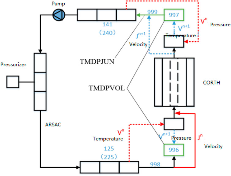
Figure 2. Data transfer scheme in System-subchannel coupling code.
3 Code validation against LOFT experiment results
3.1 Description of experiment case LOFT L6-5
The LOFT Integral Test Facility (ITF) (Burtt, 1979) is a ∼50 MW pressurized water reactor system, which can simulate the main accident phenomena of a large commercial four-loop pressurized water reactor (1,000 MW) with a ratio of 1:42 under LOCA accidents and other transient accidents.
A number of experiments were carried out on the LOFT bench, including large-break experiments with and without cores, medium-break experiments, small-break experiments, steam generator heat transfer tube rupture experiments, and non-break loop transient experiments. The experimental results help to deepen the understanding of some unexpected phenomena such as thermal-hydraulic, mechanical and nuclear responses of the reactor system under accident conditions.
On 29 May 1980, the L6-5 experimen (Olding and Lambert, 1982) was carried out on the LOFT ITF. The L6-5 experiment is a transient experiment about loss of feedwater supply on secondary side. It is one of the LOFT non-LOCA L6 experiment series. At the start of the L6-5 experiment, the nuclear power was 36.7 ± 1 MW, (the maximum line power was 39.6 ± 2 kW/m), the primary loop flow was 479.4 ± 6.3 kg/s, the hot leg temperatures were 568.2 ± 0.5 K and 554.7 ± 3K respectively, and the hot leg pressure was 14.95 ± 0.34 MPa. After shut-down of the main feed water pump of the secondary circuit, the experiment started. When the liquid level on the secondary side of the steam generator drops to the set point, the reactor is manually shut down. The liquid level in the steam generator and pressure Pressurizer is restored by operating operations. The experiment was terminated when the liquid levels in the steam generator and Pressurizer returned to the normal operating levels. Neither the injection suppression system nor the emergency core cooling system was put into use. The coolant in the broken loop did not flow during the entire experiment, so it only played the role of passive heat transfer.
The specific goals of Experiment L6-5 are:
1) To analyze the transient response of the reactor when the secondary side water supply is completely cut off;
2) To evaluate the reactor’s automatic recovery measures;
3) To provide experimental data to evaluate the code’s capability to evaluate secondary side system accidents.
3.2 Modeling of experiment case
Based on the layouts of the LOFT experimental bench and the core, as shown in Figures 3–6, the models of ARSAC and CORTH were established. The core of the LOFT IFT consists of 5 square assemblies and 4 triangular assemblies. The square assembly has 225 rod positions (15 rod positions on each side), 21 of which are guide tubes. The triangular assembly contains 78 rod positions, 8 of which are guide tubes.
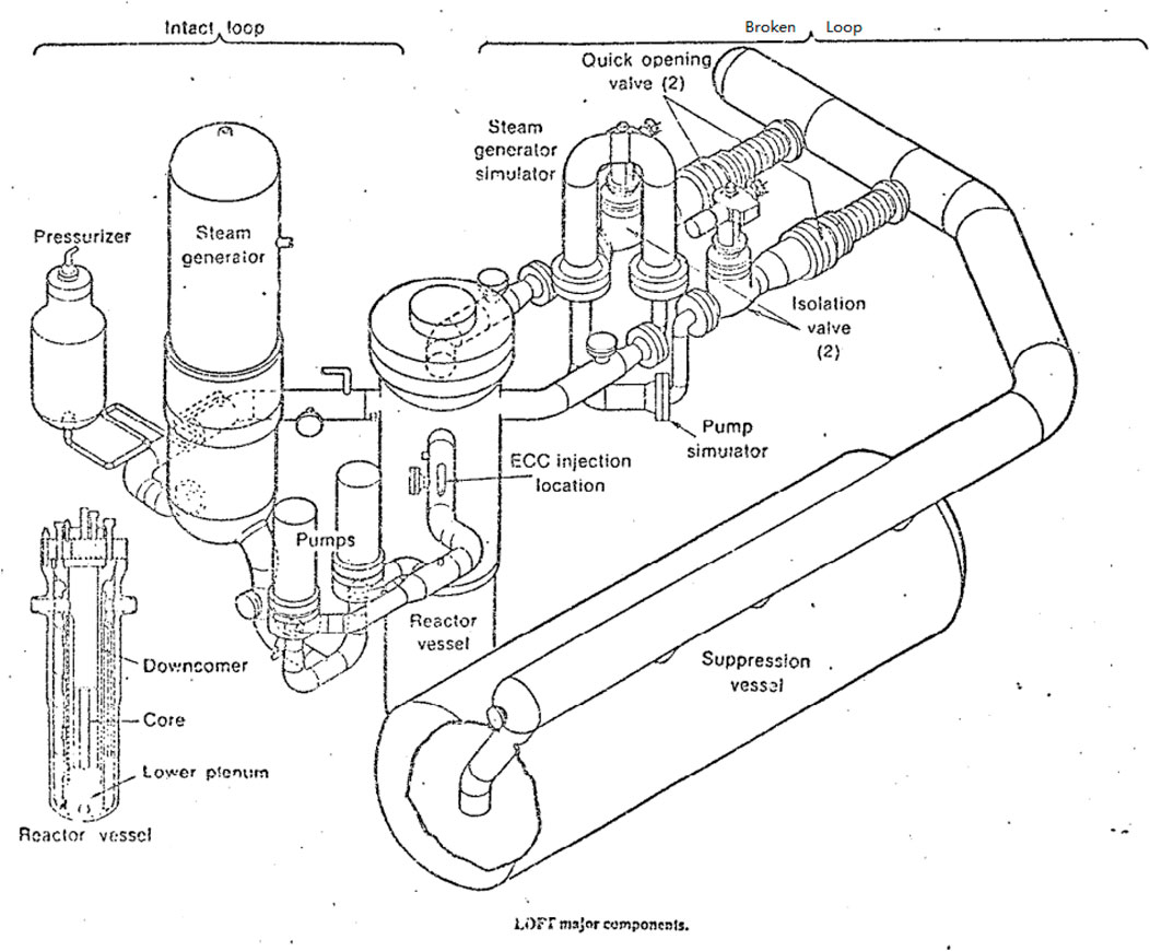
Figure 3. Layout of LOFT bench.
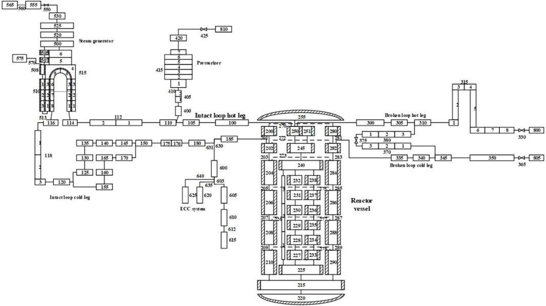
Figure 4. Schematic diagram of node division of LOFT bench.
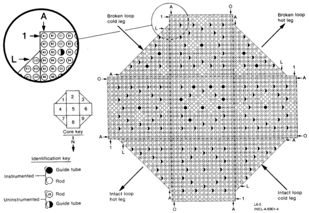
Figure 5. Schematic diagram of LOFT core layout (Olding and Lambert, 1982).
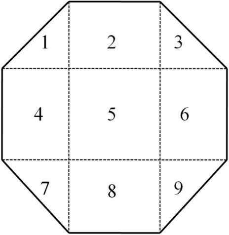
Figure 6. LOFT core sub-channel division.
3.3 Results and analysis
Based on the models established above, the ARSAC-CORTH coupling code was used to simulate the L6-5 non-break transient experiment, and the initial steady-state condition at the start of the experiment was established.
The comparison results between the initial conditions obtained by steady-state calculation and experimental values are shown in Table 1. It can be seen from the table that, except for the feedwater temperature on the secondary side of the steam generator, the calculated main thermal and hydraulic parameters are all within the allowable error range, and transient calculations can be carried out accordingly.
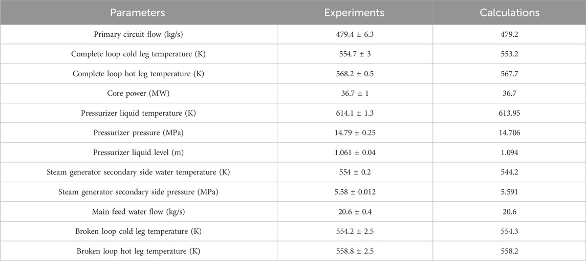
Table 1. LOFT L6-5 initial steady state calculation results.
The transient calculation duration is 3,000 s, and the time step is set to 0.005 s. The pressure changes in the primary and secondary loops are shown in Figures 7, 8. At the beginning of the experiment, the main feed water pump was shut down and the flow rate of main feed water decreased, resulting in deterioration of heat transfer from the primary loop to the secondary loop and an instantaneous increase in primary circuit pressure. Before the reactor shutdown, the pressure of primary loop increased due to the deterioration of heat transfer in the secondary circuit.

Figure 7. Evolution of pressure of steam generator on secondary side.
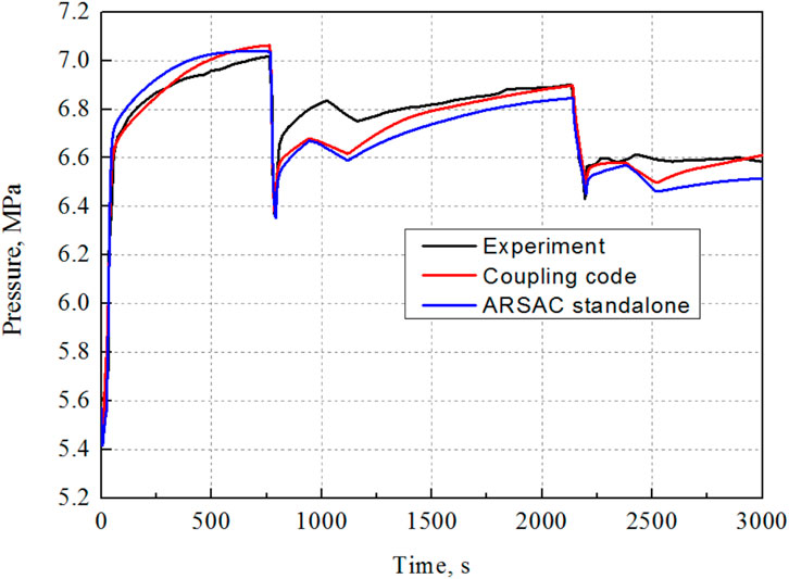
Figure 8. Evolution of pressure of pressurizer.
At 23.7 s, the reactor core shut down and the power began to decrease according to the decay power curve. At 27.6 s, the isolation valve for feedwater supply was completely closed and the main feedwater supply was cutoff. When the flow rate of feed water was reduced, a large amount of coolant on the secondary side evaporates, causing the secondary side pressure to begin to increase. At 35.4 s, the main steam flow control valve is closed, and the pressure on the secondary side rises rapidly. When it reached about 6.6 MPa, the rising rate began to decrease until it reaches the opening pressure of the main steam flow control valve. About 60–767.6 s, the steam slowly evaporated and the SG secondary side pressure also slowly increased.
After the reactor shut down, the temperature of the hot leg decreased and the pressure of primary loop decreased rapidly. When it is lower than 14.5 MPa, the heating function of Pressurizer was activated, and the primary circuit pressure began to rise again. Due to the deterioration of heat transfer between primary loop and secondary loop, the temperature of the cold leg increased. Moreover, due to the sharp deterioration of heat transfer in U-shaped tubes, the temperature of the SG entrance and exit chambers was basically the same. After about 350 s, the spray of Pressurizer started and the pressure of Pressurizer decreased again.
During the experiment, the pressure on SG secondary side was controlled by the steam flow control valve. At 767.6 s, the steam flow control valve opened, and the SG secondary side pressure dropped sharply, bringing out a large amount of steam. After 791.1 s, the steam flow control valve was closed again, and the pressure slowly increased again.
After the steam flow control valve is opened, the pressure on the secondary side of the SG decreases rapidly, and the coolant evaporated and took away a large amount of heat, causing the primary circuit pressure to also drop rapidly. Later, the opening of the steam bypass valve between 2,142 s and 2,200 s also had the same impact on the pressure of Pressurizer.
Between 937.2–1,111.7 s and 2,377.3–2,511.3 s, the upper injecting pump of ECC started and injected coolant into the primary loop with a flow rate of 0.46L/s. After starts of the injecting systems, the pressure of Pressurizer increased rapidly, and then oscillated within the opening and closing range of the Pressurizer’s pressure relief valve. After the upper injecting system shut down, the spray system started and the pressure of Pressurizer decreased. After the spray system automatically shut down, the pressure of Pressurizer slowly increased again.
From the first injecting time to the opening of the steam bypass valve, the pressure on SG secondary side has been slowly increasing. Between 2,142 and 2,200 s, the steam bypass valve opened, the pressure on SG secondary side dropped again, and the pressure of Pressurizer pressure dropped rapidly again. After 2,400 s, the pressure on SG secondary sid increased and then remained stable.
The calculation results show that the heat transfer of the primary and secondary loops deteriorates more seriously than the test results, causing the primary circuit temperature to rise sharply (Figures 9, 10), and the pressure of primary loop also arise sharply until the relief valve for Pressurizer opened. During the relief of pressure, the flow rate of primary loop dropped significantly (Figure 11). After the reactor shut down, the pressure of primary loop dropped and the flow rate of primary loop was restored after the pressure relief valve was closed.
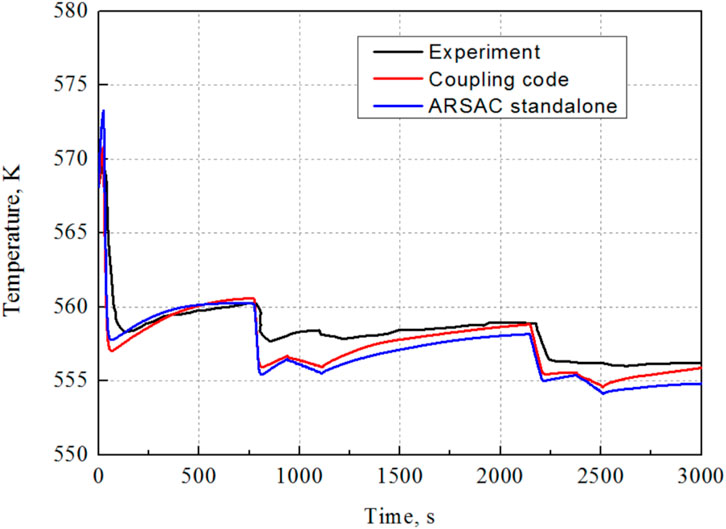
Figure 9. Temperature changes in inlet chamber of the steam generator.
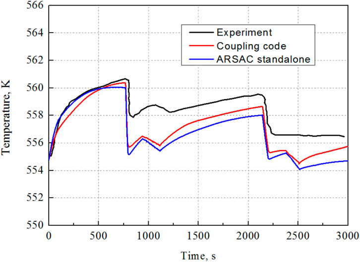
Figure 10. Temperature changes in the outlet chamber of the steam generator.
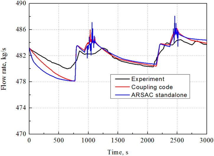
Figure 11. Changes of flow rate of primary loop.
The temperature of the SG inlet and outlet chambers is shown in Figures 9, 10. After the reactor shuts down, the temperature of the primary and secondary sides quickly reached stable value. Finally, the values of temperature of the SG inlet and outlet chambers are almost the same as that of the SG secondary side, and the temperature changed with the SG secondary side pressure. After reactor shutdown, the temperature of the SG inlet and outlet chambers was in good agreement with the experimental results. After the SG flow control valve was opened, the calculated value was 1–2 K lower than the experimental value.
The changes of the flow rate of primary loop are shown in Figure 11. After the experiment started, the primary pumps always kept running with the initial speed. However, the upper injecting pump injected water twice, which increased the flow rate of the primary loop. The flow rate decreased slowly with time, and the calculated results were in good agreement with the experimental results.
4 Conclusion
The L6-5 experiment of the LOFT IFT was simulated via the ARSAC-CORTH coupling code. The core is modeled by CORTH, and other parts of the LOFT systems are modeled by ARSAC.
About the steady-state conditions, the coupling code can effectively obtain the similar initial conditions to the experimental conditions. The errors of the main thermal hydraulic parameters are within the acceptable range, and can be used as the initial conditions for transient calculations.
During the transient condition, the coupling code can basically capture the changes in thermal parameters of the primary and secondary loops.
According the validation results, compared with ARSAC code standalone, the ARSAC-CORTH coupling code is able to better analyze the coupling effects of loop system and core, meanwhile capturing the coolant mixing between coolant channels.
Data availability statement
The original contributions presented in the study are included in the article/Supplementary Material, further inquiries can be directed to the corresponding author.
Author contributions
XW: Writing–original draft, Writing–review and editing. ZQ: Supervision, Writing–review and editing. SP: Supervision, Writing–review and editing. JD: Supervision, Writing–review and editing. WZ: Data curation, Validation, Writing–review and editing. LL: Supervision, Validation, Writing–review and editing. XiZ: Validation, Writing–review and editing, Methodology, Software. XuZ: Validation, Writing–review and editing. YX: Writing–review and editing. MW: Writing–review and editing.
Funding
The author(s) declare that no financial support was received for the research, authorship, and/or publication of this article.
Acknowledgments
The author wish to thank to the support of National Key Research and Development program of China under Grant No. 2022YFB1902300.
Conflict of interest
The authors declare that the research was conducted in the absence of any commercial or financial relationships that could be construed as a potential conflict of interest.
Publisher’s note
All claims expressed in this article are solely those of the authors and do not necessarily represent those of their affiliated organizations, or those of the publisher, the editors and the reviewers. Any product that may be evaluated in this article, or claim that may be made by its manufacturer, is not guaranteed or endorsed by the publisher.
References
Auliller, D. L., Tomlinson, E. T., and Bauer, R. C. (2002). “Incorporation of COBRA-TF in an Integrated Code System With RELAP5-3D Using Semi-Implicit Coupling,” in 2002 RELAP5 International Users Seminar, Park City, Utah, September 4–6, 2002.
Aydemir, N. U., Trottier, A., Xu, T., Echlin, M., and Chin, T. (2019). Coupling of Reactor Transient Simulations via the SALOME Platform. Ann. Nucl. Energy 126, 434–442. doi:10.1016/j.anucene.2018.11.049
Burtt, J. D. (1979). Overview of the LOFT Experimental Program. No. CONF-790646-6. Idaho Falls, ID: Idaho National Engineering Lab.
Chourdakis, G., Davis, K., Rodenberg, B., Schulte, M., Simonis, F., Uekermann, B., et al. (2022). preCICE v2: A Sustainable and User-Friendly Coupling Library. Open Res. Eur. 2, 51. doi:10.12688/openreseurope.14445.1
Duchaine, F., Jauré, S., Poitou, D., Quémerais, E., Staffelbach, G., Morel, T., et al. (2015). Analysis of High Performance Conjugate Heat Transfer with the Openpalm Coupler. Comput. Sci. Discov. 8 (1), 015003. doi:10.1088/1749-4699/8/1/015003
Escalante, J. J., Marcello, V. D., Espinoza, V. S., and Perin, Y. (2017). Application of the ATHLET/COBRA-TF Thermal-Hydraulics Coupled Code to the Analysis of BWR ATWS. Nucl. Eng. Des. 321, 318–327. doi:10.1016/j.nucengdes.2016.10.001
Fiorina, C., Clifford, I., Aufiero, M., and Mikityuk, K. (2015). GeN-Foam: A Novel OpenFOAM® Based Multi-Physics Solver for 2D/3D Transient Analysis of Nuclear Reactors. Nucl. Eng. Des. 294, 24–37. doi:10.1016/j.nucengdes.2015.05.035
Gaston, D., Newman, C., Hansen, G., and Lebrun-Grandié, D. (2009). MOOSE: A Parallel Computational Framework for Coupled Systems of Nonlinear Equations. Nucl. Eng. Des. 239 (10), 1768–1778. doi:10.1016/j.nucengdes.2009.05.021
Jeong, J. J., Ha, K. S., Chung, B. D., and Lee, W. J. (1999). Development of a Multi-Dimensional Thermal-Hydraulic System Code, MARS 1.3.1. Ann. Nucl. Energy. 26 (18), 1611–1642. doi:10.1016/s0306-4549(99)00039-0
Joppich, W., and Kürschner, M. (2006). MpCCI—a Tool for the Simulation of Coupled Applications. Concurrency Comput. Pract. Exp. 18 (2), 183–192. doi:10.1002/cpe.913
Ku, Y. T., Tseng, Y. S., Yang, J. H., Chen, S. W., Wang, J. R., and Shin, C. K. (2015). “Developments and Applications of TRACE/CFD Model of Maanshan PWR Pressure Vessel,” in 16th International Topical Meeting on Nuclear Reactor Thermal Hydraulics (NURETH-16), Chicago, IL, August 30–September 4, 2015.
Olding, C., and Lambert, P. A. (1982). RETRAN Validation: Analysis of the LOFT L6-5 Experiment. No. AEEW-R--1471. UKAEA Atomic Energy Establishment.
Papukchiev, A., and Lerchl, G. (2010). “Development and Implementation of Different Schemes for the Coupling of the System Code ATHLET With the 3D CFD Program ANSYS CFX,” in Proceedings of the NUTHOS-8 Conference, Shanghai, China, October 10–14, 2010.
Yu, Y. Q., et al. (2016). SHARP User Manual. No. ANL-NE-16/6. Argonne, WI: Argonne National Laboratory.
Zhang, K., Zhang, X., Sanchez-Espinoza, V., and Stieglitz, R. (2020b). Development of the Coupled Code–TRACE/TrioCFD Based on ICoCo for Simulation of Nuclear Power Systems and its Validation Against the VVER-1000 Coolant-Mixing Benchmark. Nucl. Eng. Des. 362, 110602. doi:10.1016/j.nucengdes.2020.110602
Keywords: system code, sub-channel code, code coupling, generic coupling architecture, code validation
Citation: Wang X, Qiu Z, Peng S, Deng J, Zeng W, Liu L, Zhang X, Zhang X, Xia Y and Wang M (2024) Development and validation of ARSAC-CORTH coupling code based on a generic coupling architecture. Front. Energy Res. 12:1400805. doi: 10.3389/fenrg.2024.1400805
Received: 14 March 2024; Accepted: 28 June 2024;
Published: 15 August 2024.
Edited by:
Wenzhong Zhou, Sun Yat-Sen University, ChinaReviewed by:
Vincent Faucher, Commissariat à l’Energie Atomique et aux Energies Alternatives (CEA), FranceIvo Kljenak, Institut Jožef Stefan (IJS), Slovenia
Copyright © 2024 Wang, Qiu, Peng, Deng, Zeng, Liu, Zhang, Zhang, Xia and Wang. This is an open-access article distributed under the terms of the Creative Commons Attribution License (CC BY). The use, distribution or reproduction in other forums is permitted, provided the original author(s) and the copyright owner(s) are credited and that the original publication in this journal is cited, in accordance with accepted academic practice. No use, distribution or reproduction is permitted which does not comply with these terms.
*Correspondence: Xilin Zhang, eGlsaW56aGFuZ19ucGljQDE2My5jb20=