 J. Baskaran1Manimaran Naghapushanam2Mahalakshmi Ganapathy3
 P. Meena4
 V. P. Meena5
 Ahmad Taher Azar6,7,8*
 Ibrahim A. Hameed9*
- 1Department of Electrical and Electronics Engineering, PSG Institute of Technology and Applied Research, Coimbatore, India
- 2Department of Electrical and Electronics Engineering, Adhiparasakthi Engineering College, Melmaruvathur, Tamil Nadu, India
- 3Department of Electrical and Electronics Engineering, Agni College of Technology, Chennai, Tamil Nadu, India
- 4Department of Electrical Engineering, Indian Institute of Technology Jodhpur, Jodhpur, Rajasthan, India
- 5Department of Electrical and Electronics Engineering, Amrita School of Engineering, Bengaluru, India
- 6College of Computer and Information Sciences, Prince Sultan University, Riyadh, Saudi Arabia
- 7Automated Systems and Soft Computing Lab (ASSCL), Prince Sultan University, Riyadh, Saudi Arabia
- 8Faculty of Computers and Artificial Intelligence, Benha University, Benha, Egypt
- 9Department of ICT and Natural Sciences, Norwegian University of Science and Technology, Alesund, Norway
Low-cost photovoltaic-powered elevators (PVPEs) have gained ever-increasing attention in the last few years for their advantages in terms of renewable energy and low maintenance costs after installation. In this paper, four high-step-up DC-DC converters for low-voltage sources such as solar photovoltaic, fuel cells, and battery banks are proposed. Their performances are evaluated in terms of optimal capability and high reliability. Among the four proposed architectures, the bootstrap converter is selected for its ability to restrict losses and other redundant parameters. The proposed converter drives the inverter-driven switched reluctance motor (SRM) assembly through a directly coupled method, which eliminates the need for battery banks while aiding in cost reduction. The prototype model is implemented, and results are validated, showing promising performance and thus being very efficacious for application to low-cost PVPEs.
1 Introduction
The photovoltaic-powered elevator (PVPE) promises to be the invention of the next few years due to its several advantages and characteristics. It is pollution-free and needs less maintenance after installation. It does not need any fuel to be powered up, and its source of power is renewable, clean, and environmentally friendly. The source of power is renewable, clean, and environmentally friendly. It is estimated that in (Cronshaw, 2015) the solar-powered apparatus is going to play the most significant role in human life. As of now, the most important equipment is motors, which utilize non-renewable energy as the main source. We are badly in need of an alternate energy source that would be renewable and reliable—none other than solar PV systems.
One easier way of making electrical energy available during calamities is solar energy. Nevertheless, the solar-powered system available traditionally is too expensive, and most of the energy is lost in conversion. If a few steps were taken to minimize these aspects, then this kind of energy would become a cheaper and maintenance-free system for several years (Caracas et al., 2013; Meghni et al., 2017). In (Raghavendra et al., 2019), the authors propose a unique converter for solar water-pumping assemblies that do not require a battery (Antonello et al., 2016; Raghavendra et al., 2019; Meena and Singh, 2023b; Fekik et al., 2023; Thanikanti et al., 2023). Then, new high-voltage-boosting converters are designed in (Hwu et al., 2012; Hwu and Yau, 2013).
When sunlight intensity crosses 1000 W/m2, which is roughly equivalent to midday in summer in Germany, for example, or when solar irradiation approaches 1000 W/m2 at lower temperatures, a module’s real power may rise above its nominal power (Sontake and Kalamkar, 2016).Two popular configurations usually employed for PV-powered systems are (i) battery-coupled and (ii) direct-coupled methods. The former approach uses the battery to increase supply over a longer period by acting as a constant voltage source for the system. But for elevators, the longer utilization period will be only during the day, when the Sun shines brightly. Though battery utilization aids in some aspects, it has its own drawbacks, as discussed below. The batteries minimize the performance of the system as the voltage is decided by the battery and not by the solar panel. Therefore, when the Sun’s luminosity is high, the nominal power can exceed 1000 W/m2 (roughly during midday), but the battery lays an obstacle to the maximum utilization of power by the system. Furthermore, the batteries have a 2-year life duration when compared to the PV module’s life span of 20 years. In addition, the cost of battery maintenance and replacement is significant. As a result, the total efficiency of the system is diminished, while the PVPE system installation cost is increased. As a result, the battery-coupled system is not employed (Eker, 2005; Meah et al., 2008; Chunting et al., 2010; Tschanz et al., 2010; Vitorino et al., 2010; Malla et al., 2011; Meena and Singh, 2022; Arun et al., 2024; Jagan et al., 2024).
In (Lee et al., 2000), interleaved operation of two or more boost converters is presented in this study for high-power applications to increase output power and reduce output ripple (Lee et al., 2000; Kengne et al., 2023). Two structures, a switched-capacitor (SC)-based boost converter and a two-level inverter, are connected in cascade in this article (Axelrod et al., 2005). To meet safety standards and make maximum use of the PV-generated power, a recent research trend in residential power generation systems is to adopt the PV parallel connected configuration rather than the series-connected design (Li and He, 2010; Meghni et al., 2018; Radwan et al., 2018; Suresh et al., 2019; Sethuraman et al., 2020). This work includes thorough mathematical analysis, detailed converter design, parameter analysis and comparison with other existing converters, and a new hardware prototype with expanded hardware results (Sathyan et al., 2015; Periyanayagam et al., 2020; Kalaiarasi et al., 2021; Meena and Singh, 2023a; Reddy et al., 2023; Meena et al., 2024; Bharatiraja et al., 2016a; Bharatiraja et al., 2016b). From the analyses made above, it is evident that an efficient and low-cost PVPE can be set up if a suitable boost converter is designed while still minimizing the conduction and switching losses for improved performance.
In this paper, we propose a detailed study of four high-step-up boost converters. Then, the most suitable topology is chosen after a careful analysis of the simulation results. In Figure 1, the overall block diagram of the proposed system is shown for better understanding of the proposed topology. The design of four types of high-step-up bootstrap converters and a multilevel inverter energizing the switched reluctance motor (SRM) according to the prevailing necessity are considered the main contributions of the work claimed in this research. The cost-reducing factor has already been discussed adequately.
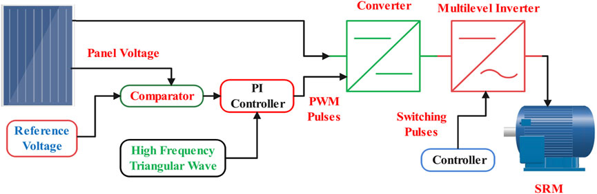
Figure 1. Block diagram of the proposed system.
The rest of this paper is organized as follows: The Section 2 elaborates on the design and selection part of the optimal bootstrap DC-DC converter and its reliable features. The multilevel-inverter-fed SRM drive is designed to provide a dynamic speed response during source variations as well as load surges in the Section 3. Section 4 shows the photovoltaic supply comparison with and without the maximum power point tracking (MPPT) controller that excites the DC-DC converter. Numerical results and hardware implementation are depicted in Section 5, while the paper’s conclusions and justifications are briefly highlighted in Section 6.
2 Selection of the DC-DC converters
There are two types of converters available for modifying the power obtained from the solar cells, which are meant for consumer-friendly use. The first is an inverter, which converts the DC into AC at the desired frequency to supply AC appliances. The other one is a DC-to dc converter, which already possesses numerous applications via DC motors for solar water pumping systems and other emerging areas like solar-powered electrical vehicles. In this proposed system, the preferred PVPE is driven by SRM; therefore, we have opted for designing a suitable boost converter and PWM inverter. As a result, various boost converters, starting from the basic conventional converter to newly proposed topologies like interleaved converters, quadruple converters, hybrid interleaved-quadruple converters, and finally bootstrap converters, were designed and simulated in this paper. The results were compared to choose the best converter according to the motor requirements.
2.1 Bootstrap converters
This converter consists of bootstrap capacitors and two boost inductors that allow the converter to work appropriately. The three switches are operated in a fashion where only half bridge and one low side gate drive are triggered. The bootstrap converter simulation circuit is shown in Figure 2.
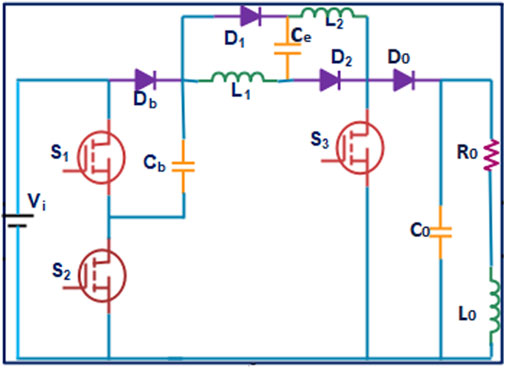
Figure 2. The proposed bootstrap converter.
2.2 Operating modes of the converter
Mode 1, Figure 3: When switches S1 and S3 are turned on, the capacitor Cb is immediately charged and the inductors are magnetized because the diode D0 is reverse biased due to the S3 switch being turned on.
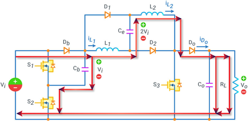
Figure 3. Continuous conduction Mode-1.
The output capacitor will provide electricity to the load during this time. The voltage across L1 and L2 in this mode can be expressed as
Mode 2, Figure 4: When switch S2 is activated, the capacitor Cb is instantaneously charged to the input voltage. The input voltage, together with the energy stored in Ce, L1 & L2 feeds the load, causing C0 to be energized and Ce discharged, L1, L2 to be demagnetized.
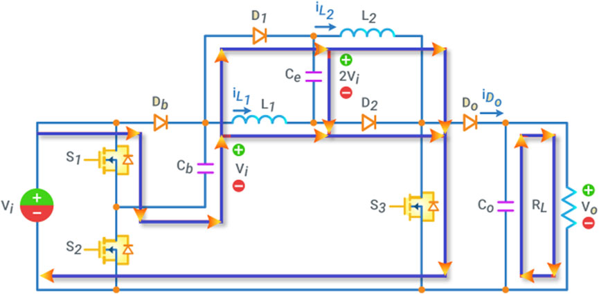
Figure 4. Continuous conduction Mode-2.
So V0 in this mode can be expressed as
The converter is operated in continuous conduction mode; the waveform is shown in Figure 5.The voltage conversion ratio in the continuous conduction mode is given by
The output response of the converter and the switching pulses are shown in Figures 6, 7. The input voltage of the converter is 24 V, the output voltage is 72 V, and the switching frequency is 5 kHz. Table 1 shows the comparison of the parameters and the responses of each boost converter. The best-suited converter for the SPWP is selected and implemented in the prototype.
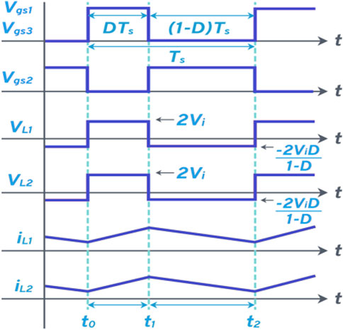
Figure 5. Continuous conduction mode waveform of the converter.
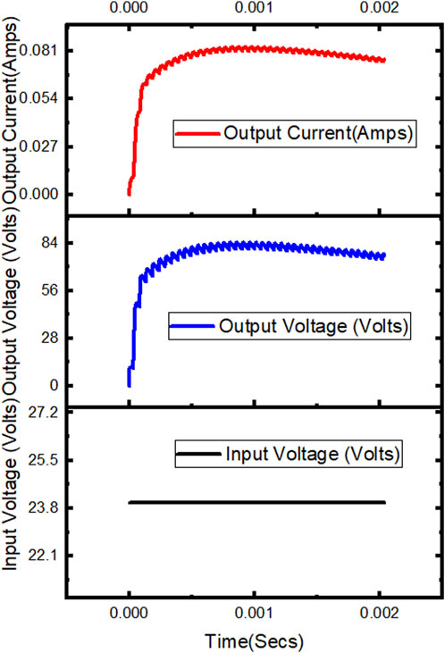
Figure 6. Simulation output of a bootstrap converter.

Figure 7. Switching pulses of the bootstrap converter.
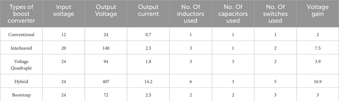
Table 1. Comparison of the results and other factors to deduce the best converter.
Taking into consideration the input voltage and output voltage, the gain is highest in a hybrid converter. And then, bearing in mind the current limitations due to some saturation facts of SRM, we turn on the interleaved and bootstrap converters. However, a few primary parameters, like the number of inductors, capacitors, and switches that would be able to avoid bulkiness, offer a better power factor, and have low switching losses, can be taken into account when picking a suitable converter among the two. Thus, we chose the bootstrap converter with two inductors, two capacitors, and 3 MOSFET switches, which can offer three times the input voltage with maximum compatibility.
3 Multilevel-inverter fed SRM drive operating principle
The multilevel-inverter-fed SRM drive is designed to provide a dynamic speed response during source variations as well as load surges in this section. Figure 8 illustrates the energy flow diagram of the proposed multilevel inverter topology (Phase A) at various levels. When the DC supply is given to the circuit, all three capacitors C1, C2 and C3 get charged. The DC voltage across the capacitors is equally divided, i.e.,
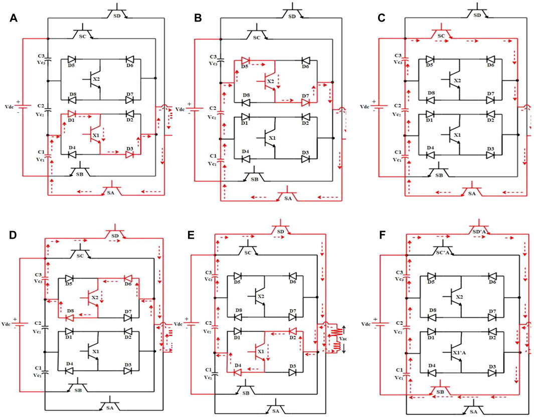
Figure 8. Energy Flow diagram of the seven level switched capacitor based symmetric multilevel inverter (SCBSMLI) at (A) Positive First level (B) Positive Second Level (C) Positive Third Level (D) Negative First Level (E) Negative Second Level (F) Negative Third Level.
To attain the first level in the positive cycle, the switches SA and X1 are excited, and the energy flows through C1 − D1 − X1 − D3 − RL − SA − C1. For the second level, the current flows through C2 − D5 − X2 − D7 − SA − C1 − C2 and C3 − SC − RL − SA − C1 − C2 − C3 for the third level. In the negative cycle, for the first level, the current flows from C3 − SD − RL − D6 − X2 − D8 − C1, for the second level, the current flows from C2 − C1 − SD − RL − D2 − X1 − D4 − C2; and C1 − C2 − C3 − SD − RL − SB − C1.
In terms of the switching conditions provided in Table 2, the gating pulses for each switch are graphed in Figure 9. In one full cycle of operation, the seven-level output is divided into 16 regions with respect to the firing angle (αn). For a seven-level switched capacitor-based symmetric multilevel inverter (SCBSMLI), the three positive half cycle levels are triggered at α1, α2, and α3, which lie between 0 and π/2, and the negative half cycle levels are triggered at α9 (=π + α1), α10 (=π + α2), and

Table 2. Switching Conditions of seven level SCBSMLI.
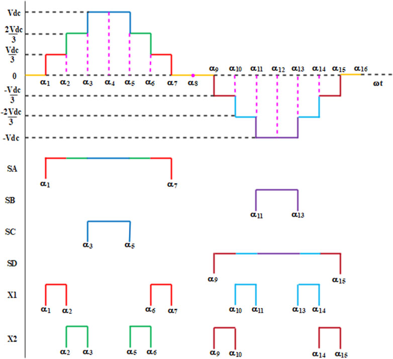
Figure 9. Gate pulses of switches SA, SB, SC, SD, X1 and X2.
The switches are turned on in the following regions:
The above switching conditions (2) and (3) are rewritten in the term of α1, α2 and α3
From the above (4) and (5), the AC output voltage of the SCBSMLI is calculated using the Fourier Half Sine series as given in the (6), since the desired output is ultimately as
where
writing (8) in terms of voltage
Substituting (5) in (8)
Substituting (2) in (9)
Integrating and simplifying (10) using trigonometric functions, the AC output voltage is for seven-level SCBSMLI given as
DC machine-like performance can be achieved for a permanent magnet synchronous motor (PMSM) drive when vector-control or field-oriented control (FOC) is used to achieve decoupling control. It is mentioned that the vector-control decouples the excitation component (id) and torque segment (iq) in PMSM by applying the instant space-vector hypothesis (Pillay and Krishnan, 1989; Bharatiraja et al., 2016a; Bharatiraja et al., 2016b). A high-precision and servo-controlled industrial robot driven by PMSM-Direct Torque Control utilizing composite active vectors is designed in (Yuan et al., 2019). The conceptual framework of antecedents to trends on permanent magnet synchronous generators for wind energy conversion systems has been briefed in (Chokkalingham et al., 2018; Padmanathan et al., 2019; Fekik et al., 2021).
The PMSM-PUMP drive comprises five primary parts: the PMSM, inverter, control unit, temperature sensor, and pump as load. The schematic representation of the drive system is shown in Figure 10. The inverter receives DC supply from the PV panel with a constant-voltage MPPT controller. Thus, the pump receives constant voltage during the day even when fluctuations are experienced in the Sun’s radiance insolation.
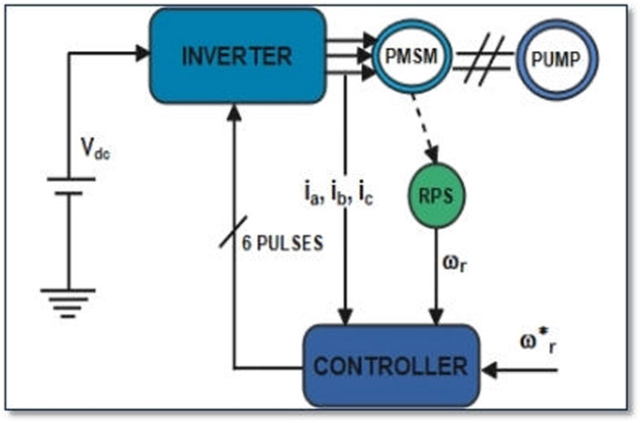
Figure 10. Schematic-representation of the PMSM-PUMP drive system.
4 MPPT controller
The proposed system is simulated, and the results are compared with the system simulated without MPPT. The MPPT-controlled bootstrap converter drives the SVM inverter to run the PMSM-PUMP assembly block diagram, as shown in Figure 11. The comparison between the proposed system without MPPT and with MPPT is done after introducing a step change in the insolation from 1,000 to 950, as exhibited in Figure 12.

Figure 11. Block diagram of bootstrap converter and SVM inverter with MPPT controller.

Figure 12. Response of the proposed system with and without MPPT.
Following the insolation graph, the other parameters like Vpv, Ppv, Vout, and speed of the motor are obtained and compared with the system without MPPT to show the superiority of the proposed system.
A comparison of output voltage and motor speed with and without MPPT is delineated in Table 3. By using the MPPT controller, the output voltage is enhanced from 385V to 415V, and motor speed is also enhanced from 1200 RPM to 1415 RPM. The panel voltage and power also seem to be improved in the MPPT-controlled system.
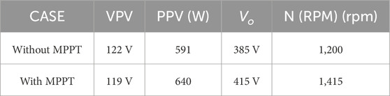
Table 3. Comparison of output voltage and motor speed with and without MPPT.
From Table 3, it is evident that the system with MPPT is showing better results than the system without MPPT. Also, the desired values are obtained, and the response is stable for the system with the MPPT technique.
5 Experimental setup & results
Thus, after the design of the proposed system, the implementation of the prototype model is carried out. Its results are validated with the proposed topology, and the challenges of implementation are summarized. Figure 13 shows the hardware setup of the proposed topology. The bootstrap converter is designed, and its output is shown in the DSO. The solar panel supplies the DC voltage for the bootstrap converter, and the constant voltage MPPT technique is employed to offer the required output as per the motor ratings. The motor speed response is converted into serial input, and then it is sent to the COM-8 port of the computer, where it is displayed on the monitor. The hardware parameters of the bootstrap are given in Table 4.
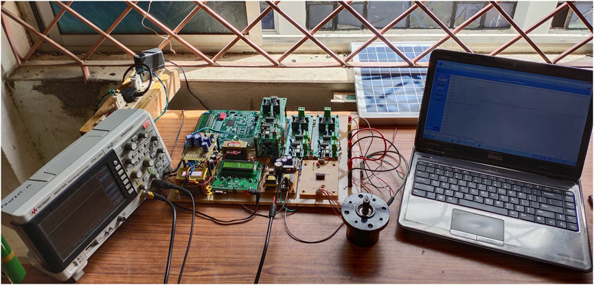
Figure 13. Hardware of the proposed topology.
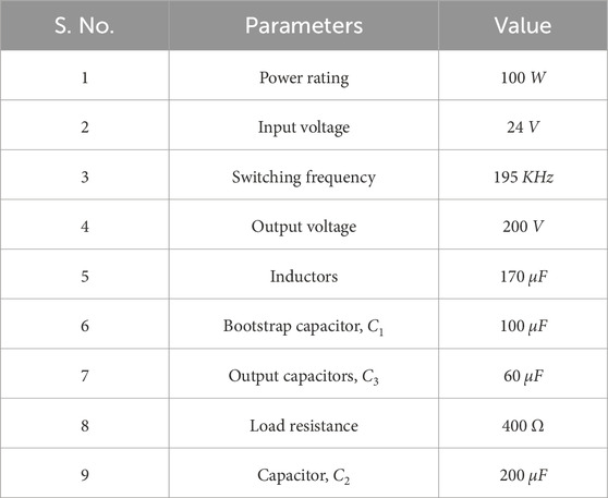
Table 4. Hardware parameters of bootstrap converter.
Figure 14 shows the output of the bootstrap converter from the hardware implemented for the purpose of giving constant dc voltage equal to 23.7 V and current of 142 mA to the inverter which drives the SRM. Then Figure 15 gives the speed response of the SRM to deliver a constant speed to the ELEVATOR load even if any disturbance occurs.
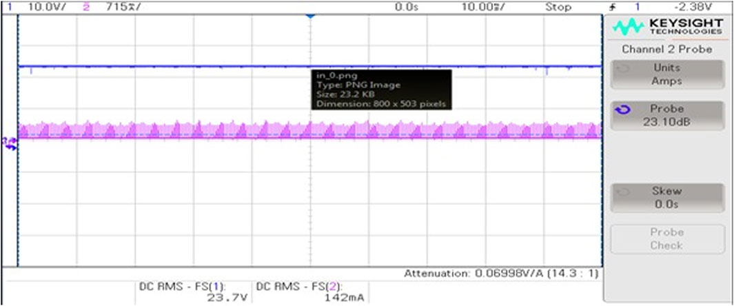
Figure 14. Output of the bootstrap converter from the hardware implemented.
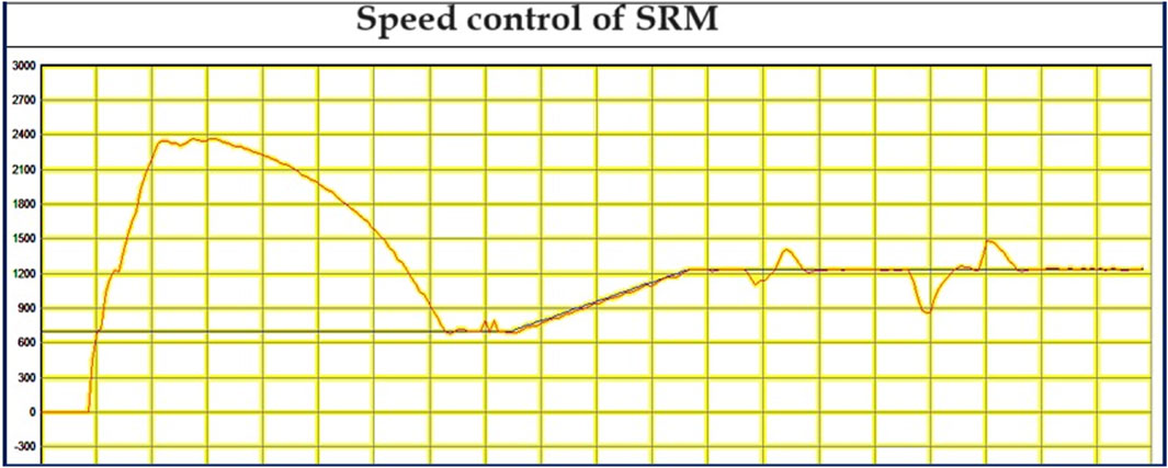
Figure 15. The speed response of the SRM with constant speed to the pump with load disturbance.
6 Conclusion and future works
This work has introduced four architectures of DC-DC converters for possible application in low-cost PVPEs. Results and comparisons from simulations show that the proposed bootstrap converter provides an enhanced output and small voltage pressure on the switches. In the projected topology, only two inductors are used for high-voltage output applications. In different operations, the converter just handles two duty ratios. Thus, we can minimize the overall cost of the solar-powered water elevator system by reducing processes like battery installation, maintenance, and further switching losses due to the DC-AC alteration stage. The direct DC-DC boost converter coupled configuration might also provide additional cost reduction. In our solution, the SRM is used as the drive for the elevator. The speed response of the SRM is guarded by a multilevel inverter controller, which ensures the stability of the whole system. The bootstrap converter supplying DC to the inverter that excites the SRM to drive the prototype is finally implemented.
Future work will focus on refining the proposed bootstrap converter architecture to optimize its efficiency and performance further. Additionally, research will explore integrating advanced control strategies to enhance the overall stability and reliability of the solar-powered water elevator system.
Data availability statement
The original contributions presented in the study are included in the article/Supplementary material, further inquiries can be directed to the corresponding author.
Author contributions
JB: Conceptualization, Formal Analysis, Methodology, Resources, Software, Writing–original draft, Writing–review and editing. MN: Conceptualization, Formal Analysis, Methodology, Resources, Software, Writing–original draft, Writing–review and editing. MG: Conceptualization, Formal Analysis, Methodology, Resources, Software, Writing–original draft, Writing–review and editing. PM: Conceptualization, Formal Analysis, Methodology, Resources, Software, Writing–original draft, Writing–review and editing. VM: Conceptualization, Formal Analysis, Methodology, Resources, Software, Writing–original draft, Writing–review and editing. ATA: Conceptualization, Formal Analysis, Investigation, Methodology, Validation, Writing–original draft, Writing–review and editing. IH: Formal Analysis, Funding acquisition, Investigation, Methodology, Resources, Validation, Writing–review and editing.
Funding
The author(s) declare that financial support was received for the research, authorship, and/or publication of this article. This research was funded by the Norwegian University of Science and Technology.
Acknowledgments
The authors would like to acknowledge the support of the Norwegian University of Science and Technology for paying the Article Processing Charges (APC) of this publication. This research is supported by Automated Systems and Soft Computing Lab (ASSCL), Prince Sultan University, Riyadh, Saudi Arabia. The authors would like to thank Prince Sultan University, Riyadh, Saudi Arabia for their support.
Conflict of interest
The authors declare that the research was conducted in the absence of any commercial or financial relationships that could be construed as a potential conflict of interest.
Publisher’s note
All claims expressed in this article are solely those of the authors and do not necessarily represent those of their affiliated organizations, or those of the publisher, the editors and the reviewers. Any product that may be evaluated in this article, or claim that may be made by its manufacturer, is not guaranteed or endorsed by the publisher.
References
Antonello, R., Carraro, M., Costabeber, A., Tinazzi, F., and Zigliotto, M. (2016). Energy-efficient autonomous solar water-pumping system for permanent-magnet synchronous motors. IEEE Trans. Industrial Electron. 64, 43–51. doi:10.1109/tie.2016.2595480
Arun, R., Muniraj, R., Karuppiah, N., Kumar, B. P., and Murugaperumal, K. (2024). Automated approach to design predictive pi control scheme for gain margin specification. Int. J. Syst. Assur. Eng. Manag., 1–8. doi:10.1007/s13198-023-02238-y
Axelrod, B., Berkovich, Y., and Ioinovici, A. (2005). A cascade boost-switched-capacitor-converter-two level inverter with an optimized multilevel output waveform. IEEE Trans. Circuits Syst. I Regul. Pap. 52, 2763–2770. doi:10.1109/tcsi.2005.852205
Bharatiraja, C., Jeevananthan, S., Latha, R., and Mohan, V. (2016a). Vector selection approach-based hexagonal hysteresis space vector current controller for a three phase diode clamped mli with capacitor voltage balancing. IET Power Electron. 9, 1350–1361. doi:10.1049/iet-pel.2015.0184
Bharatiraja, C., Jeevananthan, S., Munda, J. L., and Latha, R. (2016b). Improved svpwm vector selection approaches in ovm region to reduce common-mode voltage for three-level neutral point clamped inverter. Int. J. Electr. Power & Energy Syst. 79, 285–297. doi:10.1016/j.ijepes.2016.01.002
Caracas, J. V. M., de Carvalho Farias, G., Teixeira, L. F. M., and de Souza Ribeiro, L. A. (2013). Implementation of a high-efficiency, high-lifetime, and low-cost converter for an autonomous photovoltaic water pumping system. IEEE Trans. Industry Appl. 50, 631–641. doi:10.1109/TIA.2013.2271214
Chokkalingham, B., Padmanaban, S., and Blaabjerg, F. (2018). Investigation and comparative analysis of advanced pwm techniques for three-phase three-level npc-mli drives. Electr. Power Components Syst. 46, 258–269. doi:10.1080/15325008.2018.1445142
Chunting, M., Correa, M., and Pinto, J. (2010). The ieee 2011 international future energy challenge—request for proposals. Proc. IFEC, 1–24.
Cronshaw, I. (2015). World energy outlook 2014 projections to 2040: natural gas and coal trade, and the role of China. Aust. J. Agric. Resour. Econ. 59, 571–585. doi:10.1111/1467-8489.12120
Fekik, A., Azar, A. T., Hameed, I. A., Hamida, M. L., Amara, K., Denoun, H., et al. (2023). Enhancing photovoltaic efficiency with the optimized steepest gradient method and serial multi-cellular converters. Electronics 12, 2283. doi:10.3390/electronics12102283
Fekik, A., Azar, A. T., Kamal, N. A., Denoun, H., Almustafa, K. M., Hamida, L., et al. (2021). “Fractional-order control of a fuel cell–boost converter system,” in Advanced machine learning technologies and applications: proceedings of AMLTA 2020 (Springer), 713–724.
Hwu, K., and Yau, Y. (2013). High step-up converter based on coupling inductor and bootstrap capacitors with active clamping. IEEE Trans. Power Electron. 29, 2655–2660. doi:10.1109/tpel.2013.2289387
Hwu, K.-I., Chuang, C., and Tu, W. (2012). High voltage-boosting converters based on bootstrap capacitors and boost inductors. IEEE Trans. Industrial Electron. 60, 2178–2193. doi:10.1109/tie.2012.2194972
Jagan, V., Maheshwaram, B. C., Usirikapally, M., Balachandran, P. K., Reddy, B. N., Mettu, S., et al. (2024). Analysis of different pwm techniques for enhanced ultrahigh gain z-network topology. Int. Trans. Electr. Energy Syst. 2024, 1–14. doi:10.1155/2024/6645798
Kalaiarasi, N., Subhranshu, S. D., Paramasivam, S., Bharatiraja, C., et al. (2021). Investigation on anfis aided mppt technique for pv fed zsi topologies in standalone applications. J. Appl. Sci. Eng. 24, 261–269.
Kengne, E. R. M., Kammogne, A. S. T., Siewe, M. S., Tamo, T. T., Azar, A. T., Mahlous, A. R., et al. (2023). Bifurcation analysis of a photovoltaic power source interfacing a current-mode-controlled boost converter with limited current sensor bandwidth for maximum power point tracking. Sustainability 15, 6097. doi:10.3390/su15076097
Lee, P.-W., Lee, Y.-S., Cheng, D. K., and Liu, X.-C. (2000). Steady-state analysis of an interleaved boost converter with coupled inductors. IEEE Trans. industrial Electron. 47, 787–795. doi:10.1109/41.857959
Li, W., and He, X. (2010). Review of nonisolated high-step-up dc/dc converters in photovoltaic grid-connected applications. IEEE Trans. industrial Electron. 58, 1239–1250. doi:10.1109/tie.2010.2049715
Malla, S. G., Bhende, C., and Mishra, S. (2011). “Photovoltaic based water pumping system,” in 2011 international conference on energy, automation and signal (IEEE), 1–4.
Meah, K., Ula, S., and Barrett, S. (2008). Solar photovoltaic water pumping—opportunities and challenges. Renew. Sustain. Energy Rev. 12, 1162–1175. doi:10.1016/j.rser.2006.10.020
Meena, V., Gupta, A., and Singh, V. (2024). “Interval modelling based pid controller design for cuk converter,” in AIP conference proceedings (AIP Publishing), 2966. doi:10.1063/5.0189780
Meena, V., and Singh, V. (2023a). Controller design for a tito doha water treatment plant using the class topper optimization algorithm. Arabian J. Sci. Eng. 48, 16097–16107. doi:10.1007/s13369-023-08022-1
Meena, V., and Singh, V. (2023b). “Design of fopid controller for riverol-pilipovik water treatment plant exploiting jaya algorithm,” in 2023 international conference on computer, electronics & electrical engineering & their applications (IC2E3) (IEEE), 1–5.
Meena, V., and Singh, V. P. (2022). Kharitonov polynomial-based interval reduced order modelling of cuk converter. Int. J. Model. Identif. Control 41, 231–242. doi:10.1504/ijmic.2022.10052626
Meghni, B., Dib, D., Azar, A. T., Ghoudelbourk, S., and Saadoun, A. (2017). Robust adaptive supervisory fractional order controller for optimal energy management in wind turbine with battery storage. Fract. order control synchronization chaotic Syst., 165–202. doi:10.1007/978-3-319-50249-6_6
Meghni, B., Dib, D., Azar, A. T., and Saadoun, A. (2018). Effective supervisory controller to extend optimal energy management in hybrid wind turbine under energy and reliability constraints. Int. J. Dyn. Control 6, 369–383. doi:10.1007/s40435-016-0296-0
Padmanathan, K., Kamalakannan, N., Sanjeevikumar, P., Blaabjerg, F., Holm-Nielsen, J. B., Uma, G., et al. (2019). Conceptual framework of antecedents to trends on permanent magnet synchronous generators for wind energy conversion systems. Energies 12, 2616. doi:10.3390/en12132616
Periyanayagam, M., Kumar V, S., Chokkalingam, B., Padmanaban, S., Mihet-Popa, L., and Adedayo, Y. (2020). A modified high voltage gain quasi-impedance source coupled inductor multilevel inverter for photovoltaic application. Energies 13, 874. doi:10.3390/en13040874
Pillay, P., and Krishnan, R. (1989). Modeling, simulation, and analysis of permanent-magnet motor drives. i. the permanent-magnet synchronous motor drive. IEEE Trans. industry Appl. 25, 265–273. doi:10.1109/28.25541
Radwan, A. G., Emira, A. A., AbdelAty, A. M., and Azar, A. T. (2018). Modeling and analysis of fractional order dc-dc converter. ISA Trans. 82, 184–199. doi:10.1016/j.isatra.2017.06.024
Raghavendra, K. V. G., Zeb, K., Muthusamy, A., Krishna, T., Kumar, S. V. P., Kim, D.-H., et al. (2019). A comprehensive review of dc–dc converter topologies and modulation strategies with recent advances in solar photovoltaic systems. Electronics 9, 31. doi:10.3390/electronics9010031
Reddy, B. N., Goud, B. S., Kalyan, S., Naga, C., Balachandran, P. K., Aljafari, B., et al. (2023). The design of 2s2l-based buck-boost converter with a wide conversion range. Int. Trans. Electr. Energy Syst. 2023, 1–17. doi:10.1155/2023/4057091
Sathyan, S., Suryawanshi, H. M., Ballal, M. S., and Shitole, A. B. (2015). Soft-switching dc–dc converter for distributed energy sources with high step-up voltage capability. IEEE Trans. Industrial Electron. 62, 7039–7050. doi:10.1109/tie.2015.2448515
Sethuraman, S. S., Santha, K., Mihet-Popa, L., and Bharatiraja, C. (2020). A modified topology of a high efficiency bidirectional type dc–dc converter by synchronous rectification. Electronics 9, 1555. doi:10.3390/electronics9091555
Sontake, V. C., and Kalamkar, V. R. (2016). Solar photovoltaic water pumping system-a comprehensive review. Renew. Sustain. Energy Rev. 59, 1038–1067. doi:10.1016/j.rser.2016.01.021
Suresh, K., Chellammal, N., Bharatiraja, C., Sanjeevikumar, P., Blaabjerg, F., and Nielsen, J. B. H. (2019). Cost-efficient nonisolated three-port dc-dc converter for ev/hev applications with energy storage. Int. Trans. Electr. Energy Syst. 29, e12088. doi:10.1002/2050-7038.12088
Thanikanti, S. B., Kumar, P., Devakirubakaran, S., Aljafari, B., and Colak, I. (2023). A dynamic mismatch loss mitigation algorithm with dual input dual output converter for solar pv systems. Sol. Energy Mater. Sol. Cells 251, 112163. doi:10.1016/j.solmat.2022.112163
Tschanz, D., Lovatt, H., Vezzini, A., and Perrenoud, V. (2010). “A multi-functional converter for a reduced cost, solar powered, water pump,” in 2010 IEEE international symposium on industrial electronics (IEEE) (IEEE), 568–572.
Vitorino, M. A., de Rossiter Corrêa, M. B., Jacobina, C. B., and Lima, A. M. N. (2010). An effective induction motor control for photovoltaic pumping. IEEE Trans. Industrial Electron. 58, 1162–1170. doi:10.1109/tie.2010.2054053
Keywords: photovoltaic systems, SRM, DC-DC boost converters, multilevel-inverter, continuous conduction mode
Citation: Baskaran J, Naghapushanam M, Ganapathy M, Meena P, Meena VP, Azar AT and Hameed IA (2024) Cost-effective high-gain DC-DC converter for elevator drives using photovoltaic power and switched reluctance motors. Front. Energy Res. 12:1400651. doi: 10.3389/fenrg.2024.1400651
Received: 13 March 2024; Accepted: 18 April 2024;
Published: 06 May 2024.
Edited by:
Praveen Kumar Balachandran, Vardhaman College of Engineering, IndiaReviewed by:
Devakirubakaran S., SRM Institute of Science and Technology, IndiaPrince Winston D., Kamaraj College of Engineering & Technology, India
Copyright © 2024 Baskaran, Naghapushanam, Ganapathy, Meena, Meena, Azar and Hameed. This is an open-access article distributed under the terms of the Creative Commons Attribution License (CC BY). The use, distribution or reproduction in other forums is permitted, provided the original author(s) and the copyright owner(s) are credited and that the original publication in this journal is cited, in accordance with accepted academic practice. No use, distribution or reproduction is permitted which does not comply with these terms.
*Correspondence: Ahmad Taher Azar, YWF6YXJAcHN1LmVkdS5zYQ==; Ibrahim A. Hameed, aWJpYkBudG51Lm5v