 Junchao Ma1Zhe Wu2Ke Sun2Chenxu Wang1Chengyu Lu1Yilei Gu2Jianing Liu1Chengzhi Zhu1Hanlin Guo3
 Zheren Zhang3*Zheng Xu3
- 1State Grid Zhejiang Electric Power Co., Ltd. Research Institute, Hangzhou, China
- 2State Grid Zhejiang Electric Power Co., Ltd., Hangzhou, China
- 3Department of Electrical Engineering, Zhejiang University, Hangzhou, China
Grid-forming control is a promising solution for renewable power integration. This work presents a variable pairing scheme for the voltage controller of V/f controlled modular multilevel converter in an islanded network with a synchronous machine, which is a special type of grid-forming control. Based on the concept of the relative gain array (RGA), it is found that the RGA can be derived using steady-state sensitivity analysis. Then, the steady-state characteristics of the typical electrical components in the islanded network are considered, and the analytical expression for calculating the RGA is derived. Based on a typical system, a variable pairing scheme is then suggested using the calculated RGA elements. The time-domain simulations are conducted using PSCAD/EMTDC, and the results verify the feasibility and advantages of the suggested variable pairing scheme.
1 Introduction
The need for carbon neutralization is rapidly driving transition from non-renewable to renewable energy utilization (Abbott, 2010). The bottleneck with utilizing renewable energy depends on large-scale exploitation and wide-area allocation (Blaabjerg et al., 2023). As predicted, the renewable power capacity in China is expected to increase to approximately 1070 GW during 2022–2027, and 90% of this is in the form of wind power and photovoltaics (PVs) (IEA, 2022). The large-scale renewable energy bases are mainly distributed in the north and west regions of China, and high-voltage direct current (HVDC) is expected to play a crucial role in transmitting the generated renewable energy to the load center in the eastern part of China (Rao et al., 2019).
With the increase in converter-interfaced power sources, load centers are facing serious security and stability issues as the proportion of synchronous machine sources has decreased. The first issue is the weak grid integration of HVDC stations (Yang et al., 2018); one possible solution to this issue is the use of the voltage-source converters (VSCs) that can operate in weak or even passive systems without commutation failure risks (Yazdani and Iravani, 2010; Zhou et al., 2014). Modular multilevel converters (MMCs) are considered as the most promising VSC topology (Debnath et al., 2015; Xiao et al., 2024a) and have been successfully implemented in many bulk-power HVDC projects (Xu et al., 2020; Guo et al., 2022). The second issue is the deterioration of inertia, voltage, and frequency support; a possible solution to this issue is the use of grid-forming converters (Rosso et al., 2021; Xiao et al., 2024b). With proper grid-forming control, these converters can mimic the dynamics of the conventional synchronous generator, including the damping, inertia, voltage support, and frequency regulation characteristics (Beck and Hesse, 2007; Zhong and Weiss, 2011; Xiong et al., 2016a).
The technological evolution of grid-forming control has roughly experienced the following stages. Initially, droop control was proposed for load sharing (De Brabandere et al., 2007); then, the concept of a virtual synchronous generator was proposed for inertia emulation (Beck and Hesse, 2007). Power synchronization control was introduced to realize stable operation of converters in weak grids (Zhang et al., 2010). The design of grid-forming control is not as physically constrained as that of the synchronous generator and has greater flexibility. Thus, large amounts of research are still being conducted with the aim of improving the performances of grid-forming control schemes for the following aspects: synchronization stability, fault ride-through, and transition between control modes (Rosso et al., 2021). Pan et al. (2020) proved the equivalence of the above typical grid-forming control schemes. Droop control can be simplified to V/f control by setting the droop coefficient to 0, and V/f control is essentially a special type of grid-forming control (Yazdani, 2008). In MMC-HVDC projects, the grid-forming MMCs play important roles in islanded network connection scenarios, such as passive load supply and offshore wind-farm integration (Xiong et al., 2016b; Vidal-Albalate et al., 2016). Theoretically, grid-forming MMCs provide voltage and frequency support for islanded networks, acting as the “slack bus” or “PV bus.” Hence, grid-forming MMCs can also be connected to islanded networks with local synchronous machines. A typical scenario of this type is an offshore island power system supplied with parallel AC and DC links; when the AC link trips, the offshore island power system can continue operating if the MMC is switched to the grid-forming mode (Liu et al., 2015).
Compared to a synchronous generator, the overcurrent capability of an MMC is limited. The maximum overcurrent capability of the MMC-HVDC is usually set to 1.2 p.u. as insulated-gate bipolar transistors (IGBTs) with a rated current of more than 3 kA are extremely expensive and are not widely used in MMC-HVDC projects. To protect the MMCs from overcurrents, grid-forming control always comprises an outer voltage loop and an inner current loop in practical MMC-HVDC projects (Guan and Xu, 2012). The inner current loop is the same as that in the conventional vector current control scheme and is cascaded with the outer voltage loop.
For the grid-forming MMC in an islanded network with a synchronous machine, determining the input–output pairing scheme of the outer voltage loop is an important concern. Most grid-forming MMC-HVDC projects directly adopt the default input–output pairing scheme, where the d-axis and q-axis voltage loops generate the d-axis and q-axis current references, respectively. Although this scheme has been proven to be effective in practical MMC-HVDC projects, it remains unclear whether there exist other reasonable input–output pairing schemes or whether the extant scheme is optimal. To solve these problems, the main focus and contributions of this work considering V/f control are as follows:
(1) The variables for the input–output pairing of the voltage controller in the grid-forming MMC were clarified, and the calculation method for the index matrix of the input–output pairing scheme is proposed. With the proposed method, the complex derivation of the state-space model can be avoided via steady-state sensitivity analysis.
(2) Based on steady-state sensitivity analysis, the recommended input–output pairing scheme of the voltage controller in the grid-forming MMC is proposed. The advantages of the recommended pairing scheme are examined through time-domain simulations.
The remainder of this article is organized as follows. Section 2 introduces some basic information, such as the topology and mathematical model of the grid-forming MMC. Section 3 describes the necessity and principle of variable pairing. Section 4 describes the detailed calculation method of the index matrix for variable pairing. Section 5 presents some case studies conducted on the basis of a typical system. Section 6 presents the conclusions of this work.
2 Basics of the grid-forming MMC
Supplementary Figure S1 illustrates the typical topology of an MMC that comprises three phase units, and each phase unit is composed of an upper arm and a lower arm. Each arm contains N cascaded submodules (SMs) and an arm inductance. According to Kirchhoff’s theorem, the mathematical model of phase k (=a, b, c) can be written as Eq. (1):
Rewriting Eq. (1) with the common- and differential-mode components in phase k results in Eq. (2):
where
According to the differential-mode model, the equivalent circuit of a grid-forming MMC station connected to an islanded network with a synchronous machine can be generalized as shown in Supplementary Figure S2, where the connected AC network is represented by its Thevenin equivalent circuit (Zhang et al., 2016). In Supplementary Figure S2,
The blocks of the conventional grid-forming control scheme in the dq reference frame are shown in Supplementary Figure S3. The phase angle signal θ for the abc-dq reference frame transform is generated using the phase angle generator in Supplementary Figure S3A via V/f control or the power synchronization loop (PSL) in power synchronization control; here, ω0 is the rated angular frequency, while TJ and DJ are the time constant and damping coefficient of the PSL, respectively. The proportional–integral controller is denoted as PI. Furthermore, ud and uq are the d- and q-axis components of the PCC voltage while id and iq are the d- and q-axis components of the MMC output current in the dq reference frame, respectively. The superscript “*” indicates the reference signals;
The voltage controller in Supplementary Figure S3B generates
From Supplementary Figure S3, it is seen that V/f control is a special type of grid-forming control; given the basic voltage and current controllers, it has the most fundamental characteristic of grid-forming control, i.e., the voltage source behavior. Its difference with other types of control is that the phase angle is obtained by integrating the fixed angular frequency rather than through the droop regulator or PSL. In fact, when the droop coefficient is set to 0 or Tj is considered to be infinity, the droop control and power synchronization control will degenerate into V/f control.
3 Variable pairing for the voltage controller of grid-forming MMC
3.1 Necessity of input–output pairing in the outer loop
As a special type of grid-forming control, the block diagram of the V/f-controlled MMC station is illustrated in Supplementary Figure S4, where the connected AC system is labeled as Ggrid(s). Moreover, the voltage controller of the grid-forming MMC adopts the widely used default
Scheme 1 is stable with a small disturbance. Suppose that this system is already operating in a steady state. When there is a small increase in
For an inductive load, the increase in id causes an increase in uq because of the inductive load characteristics. Subsequently, under regulation by the voltage controller, the q-axis current reference
The aforementioned two processes are plotted in Supplementary Figure S5A,B, where the blue and red arrows respectively indicate the changes in the reference voltage and response characteristics. However, when there is a synchronous machine in the islanded network, the physical meaning of Scheme 1 is not intuitive. Considering the example of Supplementary Figure S2, the output active and reactive powers of the MMC station can be calculated as in Eq. (4):
where α is the impedance angle of Zs. It is noted that α is usually close to π/2, so it can be concluded that the active power is closely related to the voltage phase angle difference between the PCC and Thevenin equivalent voltages and that the reactive power is closely related to the PCC voltage magnitude. Considering that the steady-state phase angle of the PCC voltage is 0, the voltage phase angle difference and PCC voltage magnitude are dominated by the q- and d-axis components of the PCC voltage, respectively.
The output active and reactive powers of the MMC station can be also calculated using the d- and q-axis components of the PCC voltage and current as in Eq. (5):
Since ud and uq are approximately 1.0 p.u. and 0 p.u., respectively, the output active and reactive powers are dominated by the d- and q-axis components of the MMC output current. The above analysis indicates that the
3.2 Input–output pairing method for the outer loop
Based on Supplementary Figure S4, the block diagram of variable pairing for the voltage controller is outlined in Supplementary Figure S6, where the connected AC system, voltage controller, and MMC station plus current controller are labeled as Ggrid(s), Gv(s), and GMMC(s), respectively. It is noted that the aim of the voltage controller is to make ud (uq) track its reference
This work aims to determine the variable pairing scheme based on concept of the relative gain array (RGA) (Bristol, 1966). The RGA relies on calculating the coupling degree between the input and output of the system’s remaining part, except for the controller whose variables are to be paired. Here, the system’s remaining part includes the connected AC system and MMC station plus current controller, which is denoted as G(s) in Supplementary Figure S6. G(s) is a typical two-input two-output system, and the relative gain between the jth input and ith output (element in row i and column j of the RGA Λ) of G(s) is defined as Eq. (6):
where uin_j and yout_i are the jth input and ith output of system G(s); the numerator is the open-loop gain when all other loops are open, and the denominator is the open-loop gain when all other loops are closed with perfect control.
The variable paring can be selected on the basis of the RGA according to the following criteria: (1) when λij is closer to 1, uin_j and yout_i are paired better; (2) when λij is between 0.8 and 1.2, then uin_j and yout_i form a suitable pair, but λij beyond this range does not necessarily mean an infeasible pair. However, the RGA does not provide any information on the stability of the system. The RGA Λ can be calculated as
where G(0) is defined as G(s)|s = 0; the operation “.*” indicates the Hadamard product; G(0)−1 is the inverse matrix of G(0); and the superscript “T” is the matrix transpose.
4 Calculation of RGA for V/f-controlled MMC in an islanded network with a synchronous machine
A multi-input multi-output system can be linearized for a specified working point and generalized in its state-space form as
where x is the set of state variables; y and u are the sets of outputs and inputs; Δ is a small disturbance; and A, B, C, and D are the coefficient matrices. Therefore, the transfer function between Δu and Δy can be derived as
As noted in Section 3, only G(0) is needed to calculate the RGA Λ, and Eq. (9) can be written as Eq. (10) after setting s to 0:
Theoretically, the most intuitive method of calculating G(0) is based on the second expression in Eq. (10), which requires developing the detailed state-space model of the complete system to obtain matrices A, B, C, and D. However, these matrices are no longer needed when G(0) is calculated, and there exists another method wherein the calculation of matrices A, B, C, and D can be avoided.
According to the first expression in Eq. (10), G(0) indicates the relationship between the steady-state small disturbances in the input u and output y. In other words, G(0) is essentially the steady-state sensitivity matrix between [
Four types of typical electrical components are considered in this work: the MMC station, load, synchronous machine, and power grid network. The steady-state characteristics of these components and the complete system will be discussed separately. For simplicity, the common xy reference frame is aligned with the V/f-controlled MMC dq reference frame, and the derivations below are based on the V/f-controlled MMC’s dq reference frame. The coordinate transformation between the xy and dq frames is shown in Supplementary Figure S7; it should be noted that the real and imaginary parts in the current/voltage phasor correspond to the d- and q-axis components of the current/voltage since the common xy reference frame is already aligned with the V/f-controlled MMC’s dq reference frame.
4.1 MMC station
For the scheme shown in Supplementary Figure S4, the mathematical model of the MMC station plus current controller is described by Eqs. (11, 12):
where kp2 and ki2 are the proportion and integral gains of the current controller, respectively.
After substituting Eq. (11) into Eq. (12), GMMC(s) can be derived as in Eq. (13), and GMMC(0) is a 2 × 2 identity matrix. Therefore, the steady-state sensitivity matrix between [
4.2 Load
Three types of load models are considered in this work: constant impedance, constant current, and constant power loads. Suppose that the voltage and current phasors of the load node are
where Yl (Yl = Gl + jBl) is the admittance of the load. Thus, the steady-state voltage–current small-disturbance characteristics of the constant impedance load is as follows:
where ΔIld and ΔIlq are the real and imaginary parts of vector
For the constant current load, the steady-state voltage–current small-disturbance characteristics are described by Eq. (16):
For the constant power load, the steady-state active and reactive powers can be calculated using Eq. (17), and the derived steady-state voltage–current small-disturbance characteristics are given by Eq. (18).
4.3 Synchronous machine
Given the existence of the V/f-controlled MMC station (slack bus), a synchronous machine can be treated as either the PQ or PV bus in the steady-state analysis. Therefore, both the steady-state active power and steady-state reactive power (or terminal voltage) should be taken into account. The synchronous machine’s steady-state electrical power Pg is approximately equal to its mechanical power Pm provided the equivalent damping of the synchronous machine is small enough. For synchronous generators, Pm has a linear relationship with the rotor angular frequency as given in Eq. (19), where Pm0, ω0, ωg, and Rd are the reference mechanical power, rated rotor speed, steady-state rotor speed, and rotor speed-governor speed droop coefficient, respectively. For synchronous condensers, Pg is approximately equal to zero.
Considering the frequency support from the V/f-controlled MMC station, ωg is always equal to ω0 in the steady state, and the synchronous machine’s steady-state electrical power remains constant. Therefore, the small disturbance of the synchronous machine’s steady-state active power is 0.
Based on the above analysis, the steady-state voltage–current small-disturbance characteristics in accordance with the active power are derived as in Eq. (21), where the subscripts d and q respectively mean the real and imaginary parts of the phasor in the V/f-controlled MMC’s dq reference frame (also the d- and q-axis components).
The next step involves modeling the steady-state voltage–current small-disturbance characteristics based on the reactive power (or terminal voltage). The first mode is the constant reactive power control mode, where the synchronous machine’s steady-state reactive power Qg is constant. The steady-state voltage–current small-disturbance characteristics are as shown in Eq. (22):
The second mode is the constant terminal voltage control mode, where the steady-state terminal voltage Ug is constant. Equation (23) gives the steady-state voltage–current small-disturbance characteristics in this mode.
The third mode is the constant reactive power control mode, where the steady-state reactive power Qg has a linear relationship with the terminal voltage Ug, as shown in Eq. (24). The steady-state voltage–current small-disturbance characteristics are described by Eq. (25), where Qg0 and Kq represent the output reactive power reference and terminal voltage output reactive power droop coefficient.
4.4 Power grid network
The power grid network acts as a bridge to connect the individual components and establish the relationship between idq and udq. The steady-state analysis is based on the nodal voltage equations of Eq. (26), where the power grid network is represented by the nodal admittance matrix Y (= G + jB). By expanding Eq. (26) into the real and imaginary parts, Eq. (27) can be derived.
In Eqs. (26, 27), I(=[
With the exception of the constant current load nodes and V/f-controlled MMC station, suppose that there are k load nodes and r synchronous machine nodes in the islanded network. By rearranging Eq. (27) in the order of the V/f-controlled MMC station, load, and synchronous machine nodes, Eq. (28) can be derived. For compactness, the subscript “dq” indicates vectors containing both the d-axis and q-axis components in the V/f-controlled MMC station’s dq reference frame.
For brevity, the load current and voltage small-disturbance vectors are denoted by ΔILdq and ΔULdq, and the synchronous machine current and voltage small-disturbance vectors are denoted by ΔIGdq and ΔUGdq, respectively. Then, Eq. (28) can be expanded into Eqs. (29–31).
4.5 Steady-state sensitivity calculation
As noted in Section 4.2 and Section 4.3, the relationships between ΔILdq and ΔULdq as well as ΔIGdq and ΔUGdq can be generalized in compact form as Eqs. (32, 33), respectively.
By substituting Eqs (32, 33) into Eqs (30, 31), ΔIGdq and ΔILdq can be eliminated, and the vectors ΔUGdq and ΔULdq can be solved as linear combinations of ΔU1dq and ΔIldq, as shown in Eq. (34):
where
Substituting Eq. (34) into Eq. (29), the steady-state characteristics between ΔIldq and ΔU1dq can be derived as Eq. (36), where I is the identity matrix. Thus, the matrix G(0) (also the steady-state sensitivity matrix) can be calculated using Eq. (37).
5 Case studies
5.1 Description of the test case
The test case is shown in Supplementary Figure S8, where the power load in the islanded network is supplied by an MMC station and an AC tie line. When the AC tie line L1 is tripped, there is a need for control-mode switching (PQ to V/f mode) in the MMC station. GC in Supplementary Figure S8 represents a synchronous condenser. The parameters of this system are listed in Table 1. In this case, the constant impedance load model is adopted, and the synchronous condenser regulates the terminal voltage (20 kV side) at 1.0 p.u. The PCC voltage and frequency that are regulated by the MMC station in the V/f mode are set as 1.0 p.u. and 50 Hz, respectively. Before disconnection of AC tie line L1, both the active and reactive powers of the MMC station are both set to 0.
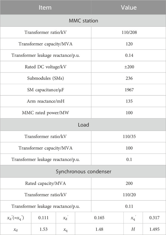
Table 1. System parameters of the islanded network supply scenario.
5.2 Input–output pairing based on RGA
First, the RGA Λ is calculated for different operating conditions with the load power restricted within 100 MVA, and the calculated elements of Λ are plotted in Supplementary Figure S9. It is observed that the default
The voltage controller for Scheme 2 is depicted in Supplementary Figure S10. To demonstrate the advantages of Scheme 2, simulation comparisons are performed between the two pairing schemes under two typical operating scenarios wherein the load is set to 80 MW + j50 MVar. Accordingly, an electromagnetic transient model of the system in Supplementary Figure S8 was built in the time-domain simulation software PSCAD/EMTDC.
5.3 Control switching from PQ to V/f modes
Before 1.0 s, the island is connected to the external system, and the MMC station operates in the PQ mode in which both the active and reactive powers are 0. At 1.0 s, the island is disconnected from the external system by tripping the AC tie line L1, and the MMC station switches to the V/f control mode at 1.05 s. The system response characteristics for the two input–output pairing schemes for the outer loop are plotted in Supplementary Figures S11, S12.
As seen from Supplementary Figures S11, S12, Scheme 2 is stable during control-mode switching while Scheme 1 loses stability. After the AC tie line is tripped, the rotor speed of GC decreases because the active power absorbed by the load is supplied by the rotor kinetic energy; at the same time, the PCC voltage decreases. When the MMC station switches to the V/f control mode, the system shows different dynamics for the two pairing schemes.
From the perspective of active power and frequency, since the steady-state frequency is set to the rated frequency, the active power of the MMC station should increase to accelerate the rotor and supply the load. From the perspective of reactive power and voltage, the MMC station should increase the output reactive power immediately after the 1.05 s mark since the steady-state PCC voltage is larger than the voltage during the 1.0–1.05 s period.
For Scheme 2, it is seen in Supplementary Figure S11 that the active and reactive powers of the MMC station generally increase during the 1.05–1.5 s period, which coincides with the active and reactive power demand mentioned above. For Scheme 1 shown in Supplementary Figure S12, as the d-axis and q-axis voltages are smaller than their reference values shortly after 1.05 s, both the q-axis and d-axis currents increase as shown in Supplementary Figure S12B. The increase in the d-axis current means increase in active power, which meets the MMC active power increase demand. However, the increase in q-axis current decreases the MMC station reactive power and conflicts with its increased demand. Thus, the reactive power is insufficient in this system, and the voltage collapse occurs as shown in Supplementary Figure S12C. The system is therefore unstable with Scheme 1. The advantage of the
5.4 Load step-change scenario
In this scenario, the AC tie line is assumed to be switched off, and the MMC station operates in the V/f control mode. Before 1.0 s, the islanded system already enters steady state. At 1.0 s, an equivalent 35 MVar of reactive power load is tripped, and the system response characteristics for the two input–output pairing schemes for the outer loop are shown in Supplementary Figures S13, S14.
According to Supplementary Figures S13, S14, since the equivalent reactive power load is tripped, the reactive power output from the MMC station should also decrease to achieve balance. For Scheme 2, the system quickly reaches a steady state without any large oscillations in the process. However, the system is unstable with Scheme 1. Therefore, the simulation results prove the advantage of the
5.5 PCC AC fault in the islanded mode
In this case, the AC tie line is assumed to be switched off, and the MMC station operates in the V/f control mode. Before 1.0 s, the islanded system already enters steady state. At 1.0 s, a solid three-phase-to-ground fault occurs at the PCC bus and is cleared 100 ms later. The system response characteristics of the two input–output pairing schemes for the outer loop are shown in Supplementary Figures S15, S16. During PCC AC fault, the PCC voltage decreases, and the PCC voltage and rotor speed decrease at the same time. When the fault is cleared, the active power of the MMC station increases to accelerate the rotor speed, and the reactive power of the MMC station should also increase to supply the load.
For Scheme 2, it is seen in Supplementary Figure S15 that the active and reactive powers of the MMC station increase when the fault is cleared, coinciding with the active and reactive power demand mentioned above. However, the system is unstable with Scheme 1. In Supplementary Figure S16, the reactive power continues decreasing to negative when the fault is cleared (during 1.1–1.4 s) regardless of the fact that the q-axis voltage keeps decreasing. The positive feedback between the reactive power and q-axis voltage deteriorates the voltage stability, and the voltage collapse at approximately 1.4 s is seen in Supplementary Figure S16. Therefore, the simulation results prove the advantage of the
6 Conclusion
This study presents and discusses the variable pairing scheme for the voltage controller of the grid-forming MMC in an islanded network with a synchronous machine based on V/f control. The conclusions of this work are summarized as follows:
1) Based on steady-state sensitivity analysis, the analytical expression for calculating the RGA is derived, and the RGA elements corresponding to the
2) The feasibility and advantages of the
Data availability statement
The original contributions presented in the study are included in the article/Supplementary Material; further inquiries can be directed to the corresponding author.
Author contributions
JM: conceptualization, methodology, and writing–original draft. ZW: formal analysis, methodology, validation, and writing–original draft. KS: formal analysis, methodology, validation, and writing–review and editing. CW: formal analysis, methodology, and writing–review and editing. CL: supervision and writing–review and editing. YG: supervision and writing–review and editing. JL: formal analysis and writing–review and editing. CZ: formal analysis and writing–review and editing. HG: visualization and writing–review and editing. ZZ: conceptualization, and writing–original draft. ZX: writing–review and editing.
Funding
The author(s) declare that no financial support was received for the research, authorship, and/or publication of this article.
Conflict of interest
Authors JM, CW, CL, JL, and CZ were employed by the State Grid Zhejiang Electric Power Co., Ltd. Research Institute. Authors ZW, KS, and YG were employed by the State Grid Zhejiang Electric Power Co., Ltd.
The remaining authors declare that the research was conducted in the absence of any commercial or financial relationships that could be construed as a potential conflict of interest.
Publisher’s note
All claims expressed in this article are solely those of the authors and do not necessarily represent those of their affiliated organizations, or those of the publisher, the editors, and the reviewers. Any product that may be evaluated in this article, or claim that may be made by its manufacturer, is not guaranteed or endorsed by the publisher.
Supplementary material
The Supplementary Material for this article can be found online at: https://www.frontiersin.org/articles/10.3389/fenrg.2024.1400285/full#supplementary-material
References
Abbott, D. (2010). Keeping the energy debate clean: how do we supply the world’s energy needs? Proc. IEEE 98, 42–66. doi:10.1109/JPROC.2009.2035162
Beck, H.-P., and Hesse, R. (2007). “Virtual synchronous machine,” in 2007 9th international conference on electrical power quality and utilisation, 1–6. doi:10.1109/EPQU.2007.4424220
Blaabjerg, F., Yang, Y., Kim, K. A., and Rodriguez, J. (2023). Power electronics technology for large-scale renewable energy generation. Proc. IEEE 111, 335–355. doi:10.1109/JPROC.2023.3253165
Bristol, E. (1966). On a new measure of interaction for multivariable process control. IEEE Trans. Autom. Contr. 11, 133–134. doi:10.1109/TAC.1966.1098266
Debnath, S., Qin, J., Bahrani, B., Saeedifard, M., and Barbosa, P. (2015). Operation, control, and applications of the modular multilevel converter: a review. IEEE Trans. Power Electron. 30, 37–53. doi:10.1109/TPEL.2014.2309937
De Brabandere, K., Bolsens, B., Van Den Keybus, J., Woyte, A., Driesen, J., and Belmans, R. (2007). A voltage and frequency droop control method for parallel inverters. IEEE Trans. Power Electron. 22, 1107–1115. doi:10.1109/TPEL.2007.900456
Guan, M., and Xu, Z. (2012). Modeling and control of a modular multilevel converter-based HVDC system under unbalanced grid conditions. IEEE Trans. Power Electron. 27, 4858–4867. doi:10.1109/TPEL.2012.2192752
Guo, C., Wu, Z., Yang, S., and Hu, J. (2022). Overcurrent suppression control for hybrid LCC/VSC cascaded HVDC system based on fuzzy clustering and identification approach. IEEE Trans. Power Deliv. 37, 1745–1753. doi:10.1109/TPWRD.2021.3096954
IEA (2022) “Renewables 2022 analysis and forecast to 2027,”. Paris France: IEA. Available at: https://www.iea.org/reports/renewables-2022.
Liu, S., Xu, Z., Tang, G., Hua, W., and Zhang, J. (2015). Study on MMC-HVDC switching scheme between grid-connected and passive islanding mode. Proc. CSEE 35, 2152–2161. doi:10.13334/j.0258-8013.pcsee.2015.09.007
Pan, D., Wang, X., Liu, F., and Shi, R. (2020). Transient stability of voltage-source converters with grid-forming control: a design-oriented study. IEEE J. Emerg. Sel. Top. Power Electron. 8, 1019–1033. doi:10.1109/JESTPE.2019.2946310
Rao, H., and Zhou, Y. (2019). Key technologies of ultra-high voltage hybrid LCC-VSC MTDC systems. CSEE JPES. doi:10.17775/CSEEJPES.2019.01140
Rosso, R., Wang, X., Liserre, M., Lu, X., and Engelken, S. (2021). Grid-forming converters: control approaches, grid-synchronization, and future trends—a review. IEEE Open J. Ind. Appl. 2, 93–109. doi:10.1109/OJIA.2021.3074028
Vidal-Albalate, R., Beltran, H., Rolan, A., Belenguer, E., Pena, R., and Blasco-Gimenez, R. (2016). Analysis of the performance of MMC under fault conditions in HVDC-based offshore wind farms. IEEE Trans. Power Deliv. 31, 839–847. doi:10.1109/TPWRD.2015.2468171
Xiao, H., Gan, H., Yang, P., Li, L., Li, D., Hao, Q., et al. (2024a). Robust submodule fault management in modular multilevel converters with nearest level modulation for uninterrupted power transmission. IEEE Trans. Power Deliv. 39, 931–946. doi:10.1109/TPWRD.2023.3343693
Xiao, H., He, H., Zhang, L., and Liu, T. (2024b). Adaptive grid-synchronization based grid-forming control for voltage source converters. IEEE Trans. Power Syst. 39, 4763–4766. doi:10.1109/TPWRS.2023.3338967
Xiong, L., Zhuo, F., Wang, F., Liu, X., Chen, Y., Zhu, M., et al. (2016b). Static synchronous generator model: a new perspective to investigate dynamic characteristics and stability issues of grid-tied pwm inverter. IEEE Trans. Power Electron. 31, 6264–6280. doi:10.1109/TPEL.2015.2498933
Xiong, L., Zhuo, F., Wang, F., Liu, X., and Zhu, M. (2016a). A fast orthogonal signal-generation algorithm characterized by noise immunity and high accuracy for single-phase grid. IEEE Trans. Power Electron. 31, 1847–1851. doi:10.1109/TPEL.2015.2478155
Xu, S., Song, Q., Zhou, Y., Meng, J., Yang, W., Zhao, B., et al. (2020). Dynamic model of the DC fault clearing process of a hybrid modular multilevel converter considering commutations of the fault current. IEEE Trans. Power Electron. 35, 6668–6672. doi:10.1109/TPEL.2019.2958495
Yang, J., Hong, C., Zhou, B., Li, H., Zhang, Y., Zhang, F., et al. (2018). “Research on the mechanism of affecting the transmission capability of HVDC connected to weak AC system considering STATCOM,” in 2018 international conference on power system technology (POWERCON) (Guangzhou, China: IEEE), 2524–2532.
Yazdani, A. (2008). “Control of an islanded Distributed Energy Resource unit with load compensating feed-forward,” in 2008 IEEE power and energy society general meeting (Pittsburgh, PA, USA: IEEE), 1–7.
Yazdani, A., and Iravani, R. (2010) Voltage-sourced converters in power systems: modeling, control, and applications. New Jersey: Wiley.
Zhang, L., Harnefors, L., and Nee, H.-P. (2010). Power-synchronization control of grid-connected voltage-source converters. IEEE Trans. Power Syst. 25, 809–820. doi:10.1109/TPWRS.2009.2032231
Zhang, Z., Xu, Z., Jiang, W., and Bie, X. (2016). Operating area for modular multilevel converter based high-voltage direct current systems. IET Renew. Power Gener. 10, 776–787. doi:10.1049/iet-rpg.2015.0342
Zhong, Q.-C., and Weiss, G. (2011). Synchronverters: inverters that mimic synchronous generators. IEEE Trans. Industrial Electron. 58, 1259–1267. doi:10.1109/TIE.2010.2048839
Zhou, J. Z., Ding, H., Fan, S., Zhang, Y., and Gole, A. M. (2014). Impact of short-circuit ratio and phase-locked-loop parameters on the small-signal behavior of a VSC-HVDC converter. IEEE Trans. Power Deliv. 29, 2287–2296. doi:10.1109/TPWRD.2014.2330518
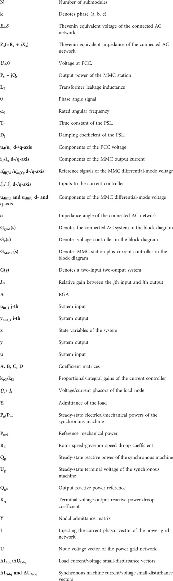
Nomenclature
Keywords: modular multilevel converter, grid-forming control, voltage controller, variable pairing scheme, relative gain array
Citation: Ma J, Wu Z, Sun K, Wang C, Lu C, Gu Y, Liu J, Zhu C, Guo H, Zhang Z and Xu Z (2024) Research on variable pairing scheme for V/f controlled MMC station. Front. Energy Res. 12:1400285. doi: 10.3389/fenrg.2024.1400285
Received: 13 March 2024; Accepted: 19 April 2024;
Published: 30 May 2024.
Edited by:
Liansong Xiong, Xi’an Jiaotong University, ChinaReviewed by:
Huangqing Xiao, South China University of Technology, ChinaXi Wu, Southeast University, China
Copyright © 2024 Ma, Wu, Sun, Wang, Lu, Gu, Liu, Zhu, Guo, Zhang and Xu. This is an open-access article distributed under the terms of the Creative Commons Attribution License (CC BY). The use, distribution or reproduction in other forums is permitted, provided the original author(s) and the copyright owner(s) are credited and that the original publication in this journal is cited, in accordance with accepted academic practice. No use, distribution or reproduction is permitted which does not comply with these terms.
*Correspondence: Zheren Zhang, MzA3MTAwMTI5NnpoYW5nQHpqdS5lZHUuY24=