
94% of researchers rate our articles as excellent or good
Learn more about the work of our research integrity team to safeguard the quality of each article we publish.
Find out more
REVIEW article
Front. Energy Res., 13 June 2024
Sec. Process and Energy Systems Engineering
Volume 12 - 2024 | https://doi.org/10.3389/fenrg.2024.1397482
This article is part of the Research TopicRecent Advances in Energy Systems for Sustainable DevelopmentView all 11 articles
 Adeola Balogun1Ayobami Olajube2
 Ayokunle Awelewa3*Sodiq Agoro4Frank Okafor1
 Timilehin Sanni3
 Isaac Samuel3
 Adejumoke Ajilore3
Diverse control strategies for enhancing operations of isolated distribution grids are reviewed. Such distribution grids are called mini-grids or micro-grids, depending on their power flow capabilities. Robust control schemes identified in other climates for mini-grid and micro-grid operations are yet to be fully explored in the Nigerian electricity supply industry (NESI). Sustainable control strategies suitable for isolated distribution grids in the NESI predicate on capabilities for diverse objectives, such as energy conservation, affordability, efficient power throughput, and utilization, for enhanced resiliency and reliability. Consequently, the distributed control system in hierarchical layers is identified as a suitable choice for mini-grid operations in Nigeria because of its robustness in scalability and in energy conservation. However, the model predictive control (MPC) scheme is observed to be uniquely applicable in all of the hierarchical control layers. Therefore, a cascade-free MPC with improved robustness against sensitivity to system parameter variation is presented at the primary control layer for an H8 voltage source inverter (VSI) used for grid integration of the solar photovoltaic (PV) system. The H8 inverter gives more promising mitigation strategies against common-mode voltage and leakage current. Moreover, the control of DC link voltage for maximum power point tracking (MPPT) is achieved by the H8 inverter, thereby eliminating the need for a separate converter for MPPT. Thus, sustainability is achieved.
Expansion of the legacy electric power grids in most emerging economies is increasingly becoming unsustainable. The Nigerian electricity supply industry (NESI), in particular, suffers from investment neglect over the last 3 decades. Therefore, the possibility of availability of electric power to every household through national grids in Nigeria has been heavily degraded.
The concept of a much smaller power grid structure trends globally as a viable alternative to the legacy national grids (Xin et al., 2011; Bhandari et al., 2014; Bidram et al., 2014; Cai et al., 2016; Golsorkhi et al., 2017; Shafiee et al., 2018; Wu et al., 2018). Such grids are termed mini- or micro-grids (Bidram et al., 2014; Cai et al., 2016; Golsorkhi et al., 2017; Shafiee et al., 2018; Wu et al., 2018; Pedrasa et al., 2006; Guerrero et al., 2013a; Guerrero et al., 2013b; Che et al., 2014; Amoateng et al., 2018), with the propensity for more flexibility in configuration (Qu et al., 2008; Arnold, 2011; Aziz et al., 2013; Li et al., 2016; Chen et al., 2017; Chu and Iu, 2017; Sahoo et al., 2017; Morstyn et al., 2018; Arfeen et al., 2019; Lai et al., 2019; Narang et al., 2020) and easier in scalability and deployment, as indicated in the following studies (Bidram et al., 2013; Liu et al., 2014a; Chen et al., 2015; Guo et al., 2015; Moayedi and Davoudi, 2016; Zuo et al., 2016; Dehkordi et al., 2017a; Antoniadou-Plytaria et al., 2017; Wu and Shen, 2017; Kumar et al., 2018; Meng et al., 2018; Dehkordi et al., 2019). Moreover, with the proliferation of renewable energy sources (RESs) in the energy mix because of near zero carbon footprints, micro-/mini-grids are becoming more competitive and attractive for investors than legacy grids. The reason for such competitiveness is partly because most RESs are usually integrated at the distribution buses (Arfeen et al., 2019), which will not require huge capital investment on equipment and manpower because of lower voltage levels of integration (Lovejoy, 1992; Bidram and Davoudi, 2012; Hazelton et al., 2014; Mipoung et al., 2014; Dang et al., 2015; Singh et al., 2015; Unamuno and Barrena, 2015; Nasirian et al., 2016; Dehkordi et al., 2017b; Arcos-Aviles et al., 2018; Castilla et al., 2019; Flowers, 1997; Lasseter, 2002; Lasseter and Paigi, 2004; Lasseter, 2011; Olivares et al., 2014; Tahir and Mazumder, 2015; Chen et al., 2016; Fioriti et al., 2017; Li et al., 2017; Moayedi and Davoudi, 2017; Chen et al., 2018; Sen and Kumar, 2018; Xu et al., 2019; Jumani et al., 2020; Mujtaba et al., 2020; Shrestha et al., 2020; Abdulkareem et al., 2022; Anand et al., 2013; Awelewa et al., 2016; Awelewa et al., 2020; Buja and Kazmierkowski, 2004; Concari et al., 2016; De Carne et al., 2015; De Carne et al., 2018; Faisal et al., 2018; Gao et al., 2017; Holmes and Lipo, 2003; Josep, 2017; Maes and Melkebeek, 2000; Nasirian et al., 2014; Nik Idris and Mohamed Yatim, 2004; Ojo and Kshirsagar, 2003; Perlack et al., 1988; Poddar and Ranganathan, 2004; Surprenant et al., 2011; Vasquez et al., 2012; Xiang et al., 2019; Zhi and Xu, 2007). Such distribution buses with power generation sources when disconnected from the national grid can operate as stand-alone grids in the islanding mode (Chen et al., 2016; Li et al., 2017, Fioriti et al., 2017; Xu et al., 2019, Flowers, 1997; Chen et al., 2018) and can be constituted as the mini- or micro-grids. Power generation systems on such grids are termed distributed generation (DG) (Arfeen et al., 2019; Mujtaba et al., 2020) or embedded generation alternatively. Such micro-/mini-grids are promising power solutions much easier to deploy to remotely off-grid sites and regions severely affected by natural disasters that have been cut off from the main grid.
Since power synchronization with the main grid is completely lost in the islanding mode, the need arises to create references for control of voltage magnitude, frequency, phase angle, and phase sequence in such mini-grids with embedded generation systems. Some other control objectives are quite essential for enhancing the flexibility, functionality, and reliability of such isolated distribution grids (Bhandari et al., 2014; Xin et al., 2011; Pedrasa et al., 2006; Guerrero et al., 2013a). As such, concepts of centralized and decentralized (Li et al., 2016; Liu et al., 2014a) control systems emerged as applicable control schemes to mini-grids and micro-grids. There has not been a generally acceptable defined demarcation between a micro-grid and a mini-grid. In some literature, the quantum of power in a micro-grid is specified to be in the range of tens of kW to hundreds of kW, while the quantity of power flow in a mini-grid could be in the range of tens of MW. In Worldbank (2024), mini-grids were defined as small, privately owned and operated systems with generating up to 10 MW (MW) capacity and a network that distributes power to several customers, which will be adopted herein. However, in (NERC, 2024) a mini-grid was defined as an integrated local generation and distribution system with installed capacity below 1 MW, capable of serving numerous end-users independent of the national grid.
In this paper, therefore, the distribution networks that constitute a mini-grid with diverse distributed generation systems such as fossil fuel-based generating systems, solar photovoltaic (PV) power plant, battery storage system, and mini-hydro systems are methodologically investigated. The power electronics converter topologies utilized for integration and primary control on such a distribution grid are reviewed, as well as the applicable control architecture, strategies, and objectives. Specific examples of efficient control strategies given by power converters are 1) maximum power point tracking (MPPT); 2) charging of batteries; 3) discharging of batteries; 4) specifying (forming) of the grid’s voltage magnitude, frequency, and phasors; 5) synchronization of the RES for power evacuation into grids. The power generation resources making up the distributed generation systems are suggested to be diversified as a technical solution for improving resiliency and reliability in the mini-grid. Critical loads are suggested to be well-placed in buses that can be constantly supplied with steady electric power. Consequently, sustainable control strategies for mini-grids in the NESI are suggested. Furthermore, a health monitoring and control scheme for all the control layers in mini-grids in the NESI is proposed.
The concepts of small autonomous grids have existed for decades in communities that are off-grid due to economic and/or technical factors (Olivares et al., 2014). In recent times, the terms “mini-grid” and “micro-grid” have been used to characterize such small grids with increased resources, functionalities, and flexibilities. The use of the term “mini-grids” on power networks can be found in literature as far back as the 1980s (Perlack et al., 1988; Faisal et al., 2018), which predates the term “micro-grids” that was introduced in the late 1990s and early 2000s by Lasseter and Paigi (2004); Lasseter (2002). Going by the terms, it is intuitive that a mini-grid must have greater power flow capability than a micro-grid. Since there is no generally acceptable range in literature that uniquely defines lower and upper boundaries for power flow within a mini-grid or a micro-grid, the lower power range within mini-grids overlap the upper power range boundaries for micro-grids. With such an overlap, the control and protection schemes that are applicable to micro-grids are equally applicable to mini-grids. The only difference would only be in the power capacities in the control and protective devices, which would be much higher for mini-grids. Moreover, more power buses will constitute a mini-grid than a micro-grid. Another significant difference could be in the voltage levels, where the voltage level in a mini-grid would be preferable at a much higher medium level for loss reduction, while the voltage level of smaller micro-grids could be more sustainable at the low voltage. In Nigeria, for example, a mini-grid can be created at the 11 kV or 33 kV bus voltage level, while a small micro-grid (or nano-grid) could be constituted at the 400 V (line–line). Therefore, a mini-grid could be a collection of buses with DERs and load units that can operate in the islanding mode autonomously and in the grid-connected mode.
Typical examples of mini-grids existing in Nigeria are found in large universities campuses; administrative estates owned by state governments with larger economic powers, such as Lagos; and estates owned by multinational organizations. On the other hand, smaller micro- and nano-grids are commonly deployed in serviced residential estates all across the nation. Most of such grids are being powered by fossil fuel-based generators, which are not sustainable for carbon footprint mitigation. Though Nigeria has vast potential for renewable power generation, investment in renewable energy-fed grids is still significantly low. Investors are usually discouraged due to inefficient energy conversion technology and lack of enough seasoned manpower. With a population of 206.14 million that is about the size of Brazil (209.3 million), Nigeria, a tropical country located close to the equator with abundant solar potentials, still suffers from not meeting its electricity demand. Though Nigeria in 2019 achieved a power generation capacity of 12,522 MW (10,142 MW from fossil fuels and 2,380 MW from hydroelectric power), only an average 4,000 MW is available for distribution with a peak of 5,222 MW. The electricity per person in Nigeria is 128 kWh/person, while that of Brazil is 2,500 kWh/person. Therefore, increase in investments in renewable energy-fed mini-grids is justified as a more sustainable path to scale up kWh/person in Nigeria.
Medium- and heavy-power household and industrial equipment are usually developed for AC power applications because of the initial advantage AC power had over DC power in voltage conversion from one level to the other. The invention of power transformers in the 19th century was the game changer in voltage step-up and step-down from one level to the other. However, this advantage is fast fading away since the advent of power semiconductors (power electronics) in the 1960s and subsequent ingenuities and developments in power converters. As such, DC power transmission and distribution had since become a competitive alternative to AC power transmission and distribution.
A typical AC mini-grid is illustrated in Figure 1. The mini-grid is a 7-bus system at a medium voltage level of 11 kV or 33 kV with connected distributed energy resources (DERs) and loads. The DERs in a hybrid mini-grid are made up of RESs, battery storage systems, and fossil fuel-based generation systems. Therefore, the 7-bus mini-grid may be principally fed by solar PV renewable energy resources as the distributed generations embedded in the buses of the mini-grid. Lithium ion batteries and lead acid batteries can be introduced as storage systems in the network to also serve as DERs and equally serve to smoothen the intermittency in power flow that may arise from RESs. Other DERs such as fossil fuel-based generation and wind/hydro can be introduced as embedded generations.
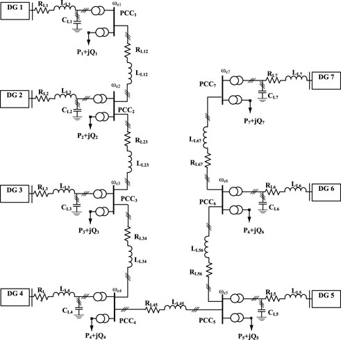
Figure 1. An illustration of a hypothetical AC mini-grid.
Electric power injection by each of the DER into a mini-grid must be adequately synchronized to the grid’s bus voltage and frequency references that must be preselected and regulated for system stability. Conventionally, a synchroscope synchronizes an AC generator into a grid’s bus, but lately phase-locked loops (PLLs) (Chung, 2000; Sheikh et al., 2017, Surprenant et al., 2011; Rasheduzzaman and Kimball, 2019) achieve such synchronization for a grid-following inverter-based RES (Kumar et al., 2017). The real power flow and reactive power flow control, load sharing control, and other control objectives in mini-grids are regulated by either centralized or decentralized control systems or combination of both in form of a hierarchical control strategy. Further discussions and illustrations on centralized, decentralized, distributed, and hierarchical control systems are given subsequently.
AC generators can inject DC power into a DC grid by connecting a rectifier of the right power capability and control. Likewise, DC power of a voltage level can be injected into a DC mini-grid of another level through DC–DC converters, such as the push–pull converters or flyback converters.
In general, the control objectives of a DC mini-grid differ from those of an AC mini-grid. Some complex control strategies in AC mini-grids do not apply to DC mini-grids. For example, a DC mini-grid will neither require frequency control nor reactive power control. Grid synchronization will also not be required. However, protection systems in DC mini-grids are more complicated because of no zero crossing point in DC currents. In addition, flow of real power without reactive power flow will degrade voltage stability. Figure 2 illustrates a DC mini-grid. Other merits and limitations of DC grids are given in (Rocabert et al., 2012; Josep, 2017, Anand et al., 2013; Nasirian et al., 2014; Wang et al., 2020).
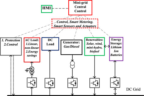
Figure 2. A block model illustration of a DC mini-grid.
A hybrid AC/DC mini-grid topology consists of the dual layout and configurations of both AC and DC mini-grids, making its control strategies more complicated. Some bus sections of such hybrid mini-grids are usually dedicated DC bus systems, while other sections constitute the AC bus systems (Rocabert et al., 2012; Lu et al., 2013).
Solar power and other RESs are very attractive electric power solutions in Nigeria and sustainable alternatives to fossil fuel-based generation, which must be encouraged into the energy mix and made more affordable. Renewables generally are intermittent sources of energy and must be controlled to have good conversion efficiencies that can yield excellent returns on investment. Since the distributed generations (DGs) in mini-grids usually comprise the hybrid renewable energy system (HRES) that is made up of the RES, energy storage system (ESS) such as battery storage system (BSS) or flywheel system, fossil fuel-fed generators and the likes, and the control architecture in a mini-grid must be a multi-task/multi-objective multi-variable control structure. Therefore, the generalized functionalities of the controllers for a stand-alone mini-grid must be responsible for the following:
1) Voltage magnitude and frequency regulation.
2) Active and reactive power flow/sharing control.
3) Load-sharing capabilities.
4) Improve efficiency in energy conversion and utilization.
5) Reduce environmental impacts of electricity supply.
6) Power supply to remote communities.
7) Improve reliability and power quality.
8) Enhance availability of steady power supply for critical loads.
9) Capability for black start during voltage collapse.
As such, the overall control architecture in a mini-grid is generally classified as follows:
1) Centralized control system
2) Decentralized control system
3) Distributed control system
4) Hierarchical control system.
The distributed control system is sometimes considered synonymously with the decentralized control system in some literature (Liu et al., 2014b), while other literature differentiates between the two (Yazdanian et al., 2014; Meng et al., 2017).
The philosophy of the centralized control system in mini-grids emanates from the configuration in which most legacy national grids were structured. In the legacy grid, usually, a central control station exists where coordinated control of power flow and power injection into the grid takes place. The control stations of legacy grids coordinate stiffness of the grid in terms of ensuring operations at constant voltage magnitudes and constant frequency. The stability profile of the legacy grid is also enhanced to prevent occurrence of unhealthy situations like voltage collapse. In the same vein, a centralized control system in a mini-grid coordinates and stabilizes power flow from every DER into load units. However, if unchecked, the point of common coupling (PCC) at which DERs are integrated into mini-grids suffers from more deviations in the voltage magnitudes and frequency, than obtained in PCCs of legacy national grids. The reason for such deviations could be derived from asymmetrical loadings on the individual phases and nonlinear loads, which are typical of distribution grids. Though the centralized control infrastructures of a mini-grid are not as huge and elaborate as those of a typical national grid, they must be able to deal with the emanating peculiarities of embedded generations. A centralized control system for a mini-grid is illustrated in Figure 2, which is equally applicable to AC grids. A major disadvantage of the centralized control system is that a single point of fault on the master control may paralyze the entire control structure. An overview of the merits and disadvantages of centralized control system are given in Yazdanian et al. (2014).
The decentralized control system does not require a central control unit. The entire control architecture is decentralized on the local controllers, which takes action by some preset or dynamic conditions in real-time. The decentralized control is differentiated from distributed control in Yazdanian et al. (2014); Morstyn et al. (2016). As such, a decentralized control method is a non-centralized control technique that assumes a negligible interaction between neighboring subsystems. In Energy (2004); Yazdanian et al. (2014), the widespread blackout of August 2003 in North America was stated as the consequence of the disadvantages of such non-centralized control. Contrarily, the distributed control system stated in Yazdanian et al. (2014) considers the interactions between control units of neighboring subsystems via communication means such as consensus-based communication links and multi-agent-based communication links. However, in Liu et al. (2014b), a decentralized control system was considered equivalent to a distributed control system. The same philosophy of multi-agent control strategies stated in Yazdanian et al. (2014) as being peculiar to the distributed control system was also attributed as decentralized multi-agent control strategies in Liu et al. (2014b). Technically, the classical decentralized control techniques, which have negligible interactions with neighboring control subsystems, evolved into more intelligent and smarter decentralized control methods, subsequently called distributed control systems.
In hierarchical control schemes, the control architecture in isolated distribution grids such as mini-grids is clearly classified into three layers, namely: 1) primary control; 2) secondary control; and 3) tertiary control. Hierarchical control strategies are well-illustrated in Zhao et al. (2016); Lu et al. (2013). The local controllers of the DERs and load distribution units are grouped under primary control, which may be completely stand-alone or have some limited interactions with neighboring local controllers. The secondary and tertiary control levels are higher-order controllers that can be responsible for higher reliability, security (e.g., cybersecurity), and situational awareness (Yazdanian et al., 2014). In Olivares et al. (2014), the hierarchical control classification was applied to both centralized and decentralized/distributed control strategies. In Shrestha et al. (2020); Rocabert et al. (2012); Hatziargyriou et al. (2006) the centralized control methodology was broken down into hierarchical classification, while in Yazdanian et al. (2014) the hierarchical classification was extensively adapted to a distributed control system. In Yazdanian et al. (2014) the tertiary control was considered the highest and slowest level of control and sets long-term set points based on the status of the DER units, market signals, and other system requirements.
A typical centralized control architecture can comprise a three-level hierarchical structure (Shrestha et al., 2020; Rocabert et al., 2012; Hatziargyriou et al., 2006), namely:
1) Local controllers, which are the local controllers on each of the DERs and load units.
2) Mini-grid central controller.
3) Distributed management system (DMS), which comprises controllers at the distribution network operator (DNO) and market operator (MO) level at medium and low voltages.
The distributed control systems for grid applications have been more flexible in design and implementation and very competitive. A distributed control architecture is illustrated in Figure 3. The droop controllers for regulating voltage magnitude and frequency are implemented at the primary control hierarchy level in distributed control systems. Examples of droop controllers in the primary level are given in Bidram et al. (2013); Meng et al., (2018). The local inverters on the DERs are responsible to implement the droop action and receive their reference command for frequency and voltage magnitude from phase-locked loop (PLL) (Li et al., 2017) (Hiskens and Fleming, 2008; Laaksonen et al., 2005) or more recently from frequency-locked loop (FLL) controllers (Sun et al., 2016) on distributed secondary control (DSC) levels in the hierarchy. Therefore, the dynamics of the DSC should be much slower than that of the primary control level (Golsorkhi et al., 2017). In a battery storage system, for example, state of charge (SoC) balancing may be required on the secondary level, but the dynamics of the DSC must be much faster than the rate of change of SoCs (Golsorkhi et al., 2017).
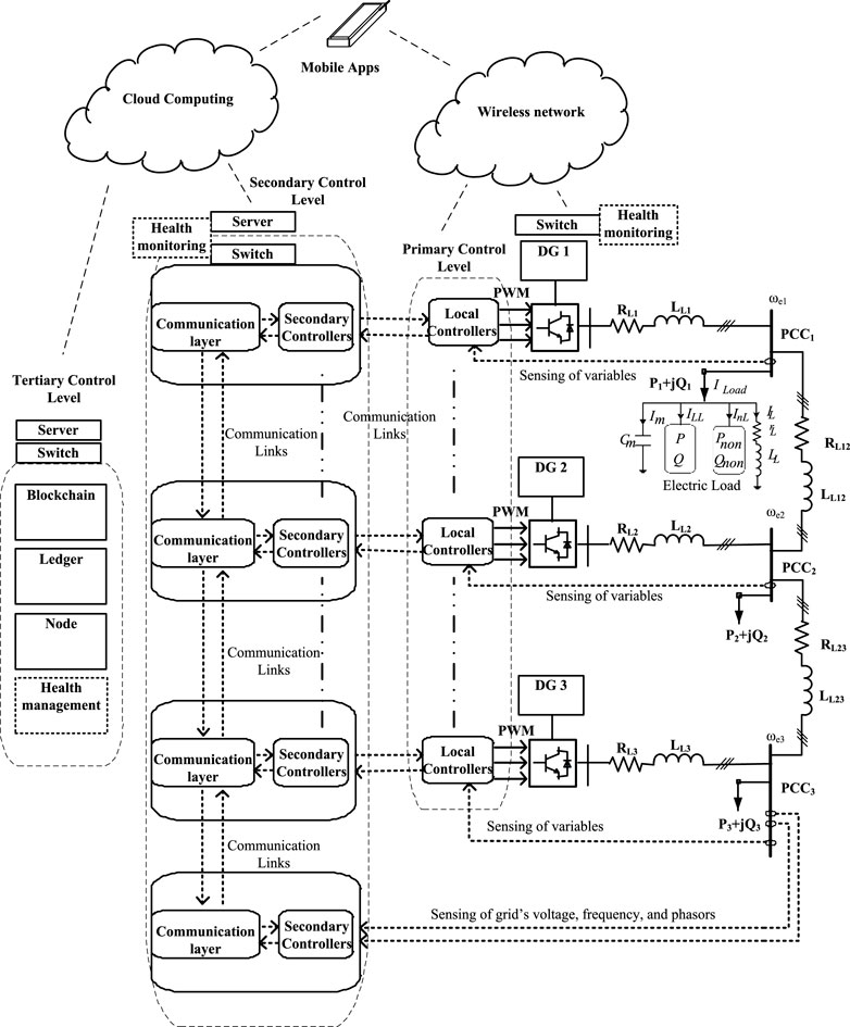
Figure 3. An illustration of a health management scheme on distributed control architecture showing hierarchical control with its communication layers in tertiary, secondary, and primary levels of a 3-bus mini-grid.
Communication networks are essential for the distributed control systems. Without such communication networks, control interactions between neighboring controllers becomes impossible. In Lu et al. (2018), a micro-grid was considered a multi-agent system, which is equally applicable to mini-grids. As such, each distributed generation (DG) is a follower–agent and receives instructions from a tertiary unit that is a virtual leader–agent. In general, a multi-agent in a distributed control system improves scalability by ensuring that each agent interacts with a few neighboring agents (and not all agents) through a sparse cyber-communication network to reduce communication infrastructure cost (Wang et al., 2020). The communication network in Lu et al. (2018) was modeled by a digraph G (V, E, A) with a node set V = {V1, V2, · · ·, VN}, a communication link set E ⊆ V × V, and a weighted adjacency matrix A = (aij)N×N, where aii = 0, aij ≥0, and aij >0 if and only if the link (Vi, Vj) ∈ E (Morstyn et al., 2018; Haimo, 1986).
Beyond implementing the generation of the reference frequency and voltage magnitude control, other compensation control strategies can also be implemented at the distributed secondary control level. The issue of unbalanced phase voltages is a common phenomenon with distribution grids that constitute mini-grids. Such an unbalanced set of phase voltages is not particularly healthy for some loads such as induction motors. The doubly fed induction generator (DFIG), which is apparently the most versatile wind generator because of its smaller converter ratings, will give rise to a negative sequence voltage that spins at a negative synchronous frequency when connected to such a mini-grid. The effect of such negative sequence voltage is that the electromagnetic torque and stator power of the DFIG will have second harmonic pulsations at twice the fundamental frequency that must be mitigated for improved quality of power flow into the grid (Balogun et al., 2015). Control compensation strategies have been implemented for such voltage unbalance in Bidram et al. (2013); Wu et al. (2018) under distributed cooperative control at the secondary level. In Wu et al. (2018), an N+1 agent communication contingency plan was implemented in the communication network at the secondary layer called distributed voltage unbalanced compensation (VUC), where N is the number of agents in the grid. The cyber network discharges the global distributed secondary control objective as a reference to the local primary controllers on the DER for enhancing the grid’s voltage magnitudes. The control infrastructure, in general, may require bandwidth for wireless communication resources that may be internet of things (IoT)-enabled. Therefore, efficient bandwidth management will be crucial for effective transmission and reception of control and monitoring signals for system devices.
A healthy mini-grid must be able to ensure steady flow of demanded power at good quality that must be free of the following:
1) Harmonics (including inter-harmonics)
2) Flickers–rapid changes in voltage magnitude
3) Voltage dips and swells
4) Complete voltage collapse
5) Frequency deviations
6) Resonance in current and voltage
7) Cyber-attacks.
A way of determining or identifying the sources of degrading power quality in a grid network is by metering the distributed generations’ points of injection and the points of load connections for power off-takers in the grid. The meters must be smart and IoT-enabled for remote monitoring and management. Moreover, the smart meters must be able to measure power in KVAhr and not only in kWhr for determining the reactive power consumption by the customers. The functionalities of the smart meters should be of those of power analyzers that can determine harmonic frequency pollutions and identify sources of harmonics.
The health monitoring and management schemes should be deployed at the three hierarchical control layers, which will be incorporated into the protection system of the grid system. At the primary control levels on the outputs of the DERs and the points of taking off-loads, the quality of the voltage, current, and power will be observed by monitoring smart meters to comply to IEEE Std 519-2014. The grid-forming inverters and grid-following inverters for grid integration are usually equipped with output filter networks which combine with the inverters for providing active filtering capabilities and compensation. Therefore, the health monitoring on the primary control initiates dynamic responses of the secondary level control to generate appropriate references for the primary control unit to adjust accordingly. The automation involved is closed loop with potentials for open-loop in case of emergencies. The secondary distribution control is illustrated in Figure 3.
The tertiary level of control and some aspects of the secondary level of control will be blockchain-enabled for keeping record of the activities of the mini-grid. The blockchain can also be used at the tertiary level of control for resolving financial billing issues by the parties involved in power generation, distribution, and consumption by the system operators. On the generation, distribution, and power off-takes, any violation of IEEE Std 519-2014 will lead to penalties, financial, or other means, that will be generated with the aid of cloud computing at the tertiary level of control and transmitted to the offending parties.
Mobile apps for remote monitoring are encouraged for mobility in health monitoring and management by the system operators (SOs). Such mobile resources will be SIM card-enabled that can use the data resources of any of the private GSM or data providers in Nigeria. The wireless communication system utilized for control and monitoring are low bandwidth resources. An illustration of a health management scheme on distributed control architecture showing hierarchical control with its communication layers in tertiary, secondary, and primary levels of a 3-bus mini-grid is shown in Figure 3.
Without converters from power electronics, achieving optimal power extractions from renewables becomes practically almost impossible. As such, power converters dictate the optimal regimes for frequency, rotor speed adjustment, and output voltage in electric machines applied in small hydro-energy and wind energy conversion systems. A unidirectional back-to-back connected converter, having a rectifier’s output tied to the input of an inverter via a DC-link capacitor, is applicable to deliver AC power from squirrel cage induction generators, wound field synchronous generators, permanent magnet synchronous generator, or synchronous reluctance generators. Those types of back-to-back converters must be rated in full capacity of such machines. It is only in DFIGs that converters are fractionally rated at 30% of machine ratings. The reason for the fractional rating is because the converters are usually connected to the rotor terminals of DFIGs, while the stator terminals do not usually require a converter interface to grids in the conventional configuration. However, the back-to-back converters can be replaced by matrix converters, which eliminate the requirement for a DC-link.
In addition, in solar power plants, maximum power point tracking (MPPT) is heavily dependent on the choice and control of the right type of converters. Equally, in the battery storage system (BSS), such as bank of lithium ion batteries, power converters are used for effective charging to maximum SoC and regulated discharge to a minimum of about 20% depth of discharge (DoD). By regulated charge and discharge, lithium ion batteries can deliver at their full cycle life. Although interests and competitiveness in use of lithium ion batteries for grid energy storage have increased in the last 2 decades because of high power densities, they are still quite expensive and require quite complex charging and discharge control strategies. Constant current charging, cell balancing, and constant voltage charging are stages that must be achieved for effective charging of lithium ion batteries. Without power converters, such charging stages cannot be achieved and consequently degrade the battery’s benefits. DC–DC converters are applicable to charging from DC mini-grids and solar power sources, while rectifiers are applicable to charging from AC mini-grids. Examples of basic DC–DC converters are buck converters, boost converters, buck–boost converters, SEPIC converters, etc. Other DC–DC converters in the form of DC power sources with electrical isolation but magnetic coupling are push–pull converters, forward converters, and flyback converters.
Three-phase voltage source inverters are frequently used by the RES for integration into AC grids via shunt injection transformers. The inverters are referred to as VSI because their input DC voltages are maintained steady via input polarized capacitors. A current source inverter (CSI), which has input current (DC) maintained as steady as possible via an inductor, exist also, but not as widely applied in the grid’s DER. The integrated RES may be solar PV modules in DC or wind/mini-hydro generators in three-phase or multi-phase (5-phase, 7-phase etc.) outputs. Multi-phase machines have been promoted in the literature because of their better resilience against open-phase faults. For example, if a three-phase generator has an open-phase fault, it can never be started up with the two remaining phases, but if a five-phase generator loses two phases, it can still be started up with the remaining three phases. As such, multi-phase generators have greater reliabilities than 3-phase generators, but their power outputs must be converted back to 3-phase via a multi-phase rectifier tied back-to-back to three-phase voltage source inverters for grid integration. The three-phase system still remains the generally acceptable standard for grid systems globally.
In grid integration application, therefore, power inverters are usually classified as grid-forming or grid-following. In the grid-forming inverter, the voltage magnitude, frequency, and phasors of the grid are fixed/determined by droop controllers (Wang et al., 2020). However, in grid-following inverters, information on the grid’s voltage magnitude, frequency, and phasors can be obtained from phase-locked loop (PLL) tied to the grid (Chung, 2000; Sheikh et al., 2017, Surprenant et al., 2011; Kumar et al., 2017; Rasheduzzaman and Kimball, 2019), which will consequently be used for generating the modulation frequency in pulse width modulation (PWM) strategies for inverters. The synchronous reference frame PLL (SRF-PLL) given in Chung (2000) is a classic PLL which is suitable for stiff grids where the phase voltages are balanced. The SRF-PLL consists of a phase detector (PD), a loop filter (LF), and a voltage-controlled oscillator (VCO).
The common modulation techniques are the carrier-based PWM(CB-PWM), the space vector PWM (SVM), and discontinuous PWM (DPWM). Other PWM schemes are given in (Hava et al., 1999; Holmes and Lipo, 2003; Ojo and Kshirsagar, 2003). Modulation schemes enable sequential turn-on and turn-off of the semiconductor devices of converters for effective operation. Analytically, modulation schemes can be embedded into the voltage equations of the inverter’s power model by the use of switching functions. In such an approach, switching functions are assigned to indicate the switching states of power semiconductor devices of the converter. The respective switching function is assigned either logic ‘1’, when the switching device (e.g. IGBT and MOSFET) is turned on, or logic ‘0’, when switched off. For a three-phase inverter system, the switching functions of the upper devices are represented by Sip and the lower devices by Sin, where the subscript i represents the respective phase, subscript p represents a positive voltage switching device, and subscript n represents a negative voltage switching device (Hava et al., 1999). By Kirchhoff’s Voltage Law (KVL), the voltage equations of the inverter in Figure 4 are as follows:
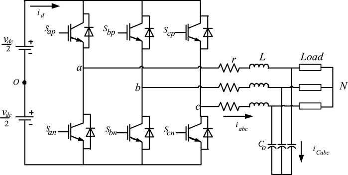
Figure 4. Three-phase 2-level inverter system.
In terms of switch function:
where
Although power converters have tremendously changed the dynamics in electric power engineering, they also pollute power networks by injecting harmonics when adequate filters are not incorporated. Common power filter configurations include C, L, RL, LC, and LCL. C stands for capacitor; L for inductor; and R for resistor. In all the configurations, the presence of little or more resistive composition is common for stability improvement. The LCL filter network is presented in Liserre et al. (2001) to give an optimal performance.
Other phenomena emanating from power converters that could degrade their applications for power integration include common-mode voltages and common-mode currents. As such, the interests in mitigating common-mode voltage by reduction or complete elimination have increased over the last 2 decades. In (Concari et al., 2016; Rahimi et al., 2018; Xiang et al., 2019), common-mode currents were seen to severely degrade power conversion from solar photovoltaic (PV) modules. In Karugaba et al. (2012), common-mode voltage was indicated to induce bearing currents in electric machines. The common-mode voltage for the inverter in Figure 4 is given as follows:
A new H8 2-level inverter was proposed in (Concari et al., 2016; Rahimi et al., 2018; Xiang et al., 2019) to have a reduced common-mode current level than conventional two-level inverters. The name 2-level is derived from switching at + Vdc (voltage of DC input) and–Vdc. In the H8 converter, two additional power semiconductor devices are introduced with each connected at the input positive and negative terminals, as illustrated in Figure 5. In Rahimi et al. (2018), the power semiconductor at the positive (+) terminal is switched on by the output of a NAND gate fed with the switching pulses of the three upper leg positive switching devices, while the negative (−) terminal is switched on by a NAND gate fed by three lower leg negative switching devices. Therefore, the sequential switching of the new semiconductors effectively cuts off the DC input power source during the null states (’000’ and ‘111’ states), thereby reducing the magnitude of the common-mode voltage and consequently minimizing the level of common-mode current flow back.
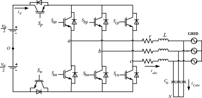
Figure 5. H8 2-level voltage source inverter.
VSI outputs are characterized by their voltage levels which determine them to be either two-level inverters or multilevel inverters. The multilevel inverter was first introduced in 1981 (Nabae et al., 1981). However, it gained more interests in the last 2 decades about the same time window when interests in the distributed grid system sprung up. The multilevel inverter introduced in Nabae et al. (1981) was a three-level neutral point clamped (NPC) inverter that switches at + Vdc, 0, –Vdc, which was unlike the 2-level NPC that switches at + Vdc and–Vdc. Subsequently, the 4-level flying capacitor (FC) and the 5-level Cascaded-H Bridge (CHB) multilevel inverters were introduced. The NPC is also known as the diode clamped because it uses diodes for clamping voltage poles. On the other hand, the FC multilevel utilizes the capacitor for its clamping, while the 5-level CHB connects VSI in series to achieve its multilevel of +2Vdc, Vdc, 0, –Vdc, –2Vdc stepping. The NPC, FC, and CHB are the classical multilevel inverters, but several other topologies are available in literature (Loh et al., 2002; Celanovic and Boroyevich, 2001; Yao et al., 2008). The modulation schemes for multilevel inverters are well-articulated in Boonchiam and Mithulananthan (2008) as phase disposition (PD), phase opposition disposition (POD), and alternate phase opposition disposition (APOD). The unique advantage of stepping up voltage in multilevel inverters and rectifiers makes them attractive for solid-state transformers (SSTs), smart transformers (STs), and other distribution grid applications.
Multistring multilevel inverters (Liao and Lai, 2011; Angirekula and Ojo, 2014; Rahim and Selvaraj, 2010) are even better replacements for CHB multilevel inverters because of their unique advantage of reduced number of power electronics devices (Agoro et al., 2018a). As such, they have lower switching losses and reduced total harmonic distortions (THDs) and consequently lower electromagnetic interference (EMI) (Angirekula and Ojo, 2014). The same multistring inverters can be switched as multistring rectifiers that can enable bi-direction flow of power. Such reverse-flow switching is also applicable to multilevel CHB inverters. Capability for bi-directional power flow gives such multilevel converters more flexibility in SST applications.
A proposed three-phase five-level multistring inverter in Agoro et al. (2018a); Balogun et al. (2019) connected to the grid through an R-L filter is shown in Figure 6A. In each phase, two PV strings are connected to six power switches through DC capacitors. The connection of these switches is such that on each side of each phase-leg, similar terminals of the switch are connected. Each PV string incorporates a MPPT control scheme that provides the appropriate reference for maximum power output.
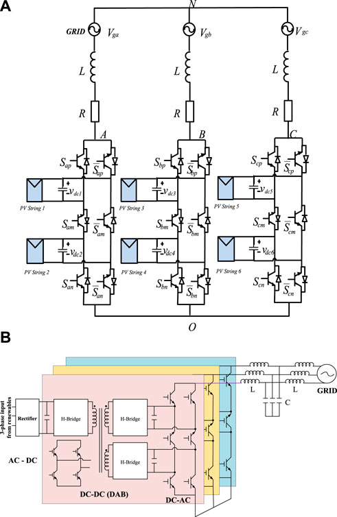
Figure 6. (A) A three-phase topology of the proposed five-level multistring inverter connected to the grid (Agoro et al., 2018a; Balogun et al., 2019). (B) A smart transformer layout developed from a three-phase five-level multistring multilevel inverter.
Interests have sprung up in the last decade on developing SSTs (She et al., 2014) and consequently smart transformers (STs) (De Carne et al., 2015; Gao et al., 2017; De Carne et al., 2018) for grid integration. Though a ST is of a much higher order of control intelligence than an SST, both are made from topologies of back-to-back connected group of converters in two or three layers for power conversion with a high frequency magnetic core isolation. With converters involved, dynamic control of real power and reactive power control becomes possible with the SST and ST. Other control objectives include harmonic elimination and power quality improvement. In Figure 6B, a smart transformer layout developed from a three-phase multistring inverter is presented. The ST has got three stages of power conversion: AC to DC rectifier, DC to DC double active bridge (DAB) converter via high frequency core (transformer), and three-phase 5-level multistring multilevel inverter. Some other STs could be arranged for a two-stage power conversion that could be applicable to directly integrate renewable into an AC grid.
Power injection into the grid network is mostly conducted in shunt (parallel) formation, whereby current is injected into the grid. Though series injection methods exist whereby series voltage is injected via special transformers, they are more complicated, which makes them not as competitive as shunt injection. A typical example depicting the two methods of injection can be found in unified power flow controllers (UPFCs). One end of the UPFC uses the series integration, while the other end utilizes the shunt injection strategy.
The voltage magnitude, frequency, and phasors in mini-grids and micro-grids must be preselected, and all connected distributed generation systems must synchronize to such. Assume that a distribution grid’s voltage equations can be given “a-b-c” reference frame as follows:
where θe = 2πfe, β = 2π/3, γ = phase angle, and fe = grid’s frequency (50 Hz in Nigeria; 60 Hz in USA). In a stiff grid like the standard legacy grid the voltage magnitude is fixed at a magnitude vm. Therefore, vm = vm1 = vm2 = vm3, and deviations in fe must be negligible. Fossil fuel-based generation responds dynamically to mitigate deviations from such conditionality because its output terminals are synchronized directly to the grid. Real power is released to mitigate frequency deviation, while reactive power flow is adjusted to enhance the stability of voltage magnitudes. However, the conditionality of electrical stiffness in grids may be difficult for a mini-grid or micro-grid to accomplish because the loading units across all phases cannot be perfectly balanced. In addition, combined nonlinear load units could influence deviation of frequency from the set point. Unlike the fossil fuel generating units, the RES and ESS in distribution grids will not directly mitigate deviations from the conditionality of stiffness unless told by some inertia emulation control. The operational frequencies of the electric machine-based RES and ESS (such as wind generators and flywheels, respectively) are completely decoupled from the grid’s frequency by the coupling inverters. Invariably, such electric machines are allowed to operate at variable speed principally for loss minimization and consequently efficiency improvement. Therefore, it is only via actuated control such as inertia emulation control that the RES and ESS can change the flow of real and reactive power for frequency and voltage magnitude control. Consequently, the SRF-PLL will be heavily degraded from predicting the grid’s frequency once vm1 ≠ vm2 ≠ vm3 in (9) to (11). Transformations of the unbalanced phase voltages into qd-reference and αβ-reference frames become riddled with harmonics and DC offsets. As such, a more robust PLL will be applicable for such a distorted grid. A method of improving the SRF-PLL is by introducing filters into the phase detection (PD stage, such that the positive and negative sequence components of the unbalanced phase voltages can be extracted. Dual second-order generalized integrator (DSOGI) is an example of the pre-filter that is applicable for such extraction (Sheikh et al., 2017; Rasheduzzaman and Kimball, 2019).
The formulation of the model for distribution grids with DER in the “a-b-c” reference frame is quite complex because of the cosines or sines in the voltage and current equations. Therefore, transformation from “a-b-c” to “q-d-0” reference frames becomes essential to ease computations because “q-d-0” eliminates such cosines or sines in variables and system parameters.
Therefore, KVL and KCL are used to model integration of solar PV power to a distribution grid. The solar PV inverter arrangement is shown in Figure 7 for storage-less topology. The voltage potentials and the nodal currents in “a-b-c” reference frames are given in Eqs 12–(14), and after transformation into “q-d” frames Eqs 15–(17) evolve. KCL is established at the DC-link by (18). At steady state, Eq. 19 gives the power balance between the inverter and the solar PV DC power. Furthermore, in Eq. 15, the inverter’s output voltage is modeled for space vector modulation (SVM) and also expressed in terms of the q-d modulation index of the inverter for a carrier-based pulse width modulation (CB-PWM). Therefore, the power being injected from the solar PV via inverter is given in Eq. 20, while the reactive power is given in Eq. 21, which can be used in load flow studies.
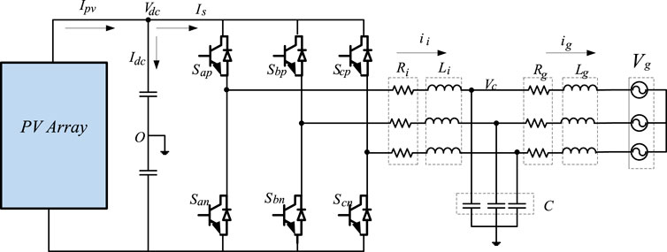
Figure 7. Topology of the storage-free grid connected PV system (Agoro et al., 2018b).
The dynamic model given in (15) to (17) could yield a non-linear system, particularly when frequency deviation occurs. Therefore, a Jacobi expansion or performing small perturbation on (15) to (17) changes the entire nonlinear dynamics into linear dynamics. If a small perturbation is performed on the model by setting the state variables x = xo + Δx about an equilibrium state xo, and then a linear small signal model emerges when higher-order terms are neglected. The small signal model given in Eq. 22 represents the state dynamics in (15) to (17). The matrix A gives the characteristic equation in (23), which predicts the regions of stability and instability. Solving (23) gives loci of eigenvalues at a given operating condition. The root loci of the eigenvalues in Eq. 23 must be restrained to the left hand plane to ensure system stability.
There are various types of linear, non-linear, and predictive control schemes available in literature for grid applications with different control objectives but with a commonality in efficiency optimization. In the RES that utilizes electric machines such as wind and hydro-energy conversion systems, variable-frequency variable-voltage control by its local controllers is essential for variable speed control. The volt per Hertz control is the simplest control strategy that can deliver variable-frequency variable-voltage regulation but at a lower efficiency than the vector control schemes. The volt per Hertz is a scalar control scheme.
In vector control, alignment of variables is usually done to achieve control schemes similar to DC controllers. Vector control is the favorite control strategies by many for industrial drive applications, and it is usually a cascade of inner-loop and outer-loop controllers. However, the inner-loop current controllers are more significant in dictating the stability of the entire control structure (Ali et al., 2020). Vector control is also applicable on grid-side converters (GSCs) by alignment of magnitude of voltage or current along the q or d axis. A vector control scheme for a grid-side converter is illustrated in Figure 8 (Balogun et al., 2021) with the magnitude of the grid’s voltage aligned along the q-axis. Orientation of variable’s magnitude along an axis usually gives a linear relationship between the controlled variable and control input. Both volt per Hertz and vector control schemes are classified under linear control systems.
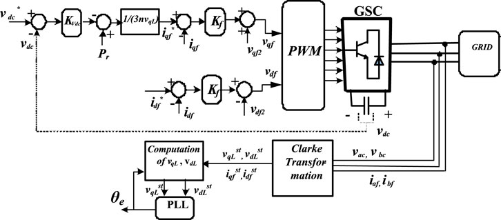
Figure 8. A vector control scheme for grid-side converters (Balogun et al., 2021).
In vector control, alignment of variables is usually done to achieve control schemes. Direct scalar control schemes such as direct torque control (DTC) and direct power control (DPC) are non-linear control schemes that are applicable to DERs. DTC strategies are applicable to machine-based RES, while DPC strategies are applicable to both machine-based RES and GSC for integrating solar PV and battery storage systems. No inner-loop current regulation is required in both DTC and DPC, which makes it less sensitive to system parameter variations, i.e., they are more robust against system parameter mismatch. Classical DTC and DPC are achieved by non-linear hysteresis controllers (Maes and Melkebeek, 2000; Buja and Kazmierkowski, 2004; Poddar and Ranganathan, 2004) with an asymmetrical switching frequency dependent on the load, but interest in symmetrical switching in DTC and DPC have yielded promising results via feedback linearization techniques and proportional plus integral (PI) controllers (Nik Idris and Mohamed Yatim, 2004; Zhi and Xu, 2007, Balogun et al., 2013; Awelewa et al., 2020, Awelewa et al., 2016; Abdulkareem et al., 2022). A DTC for a DFIG that is applicable to both wind and small hydroenergy conversion systems is illustrated in Figure 9 with symmetrical switching frequency. Similar to vector control, the direct scalar control schemes are local control strategies at the primary control level.
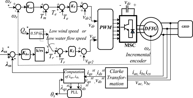
Figure 9. A direct torque control scheme with symmetrical switching for a DFIG (Balogun et al., 2013).
In grid power integration, predictive control schemes have significantly gained interests lately, principally because of their applications at all three layers of control (primary, secondary, and tertiary) (Arfeen et al., 2019). Usually, predictive control schemes are less sensitive to system parameter mismatch.
An example of such predictive control is the model predictive control (MPC) where the state space model in continuous time (CT) of the entire system is discretized into discrete time (DT) by the forward Euler’s approximation given as
The obtained discrete time model is used in deriving the predictors which are compared to preselected or dynamically obtained references in one or two cost (or objective) function(s). Classical MPC was used in chemical engineering plants, but lately, it has found interesting applications in power electronic converters. In finite set MPC, each error between a reference and a predictor in the objective function in MPC is usually characterized by a weight gain to aid the derivation of the voltage set that gives the least cost function in a prediction horizon. The conventional MPC in power converters is usually applied to the inner-loop current control, while outer loops maintain the use of PI controllers. However, a direct MPC was introduced in Agoro et al. (2018b) whereby the need for a PI outer-loop control does not arise for storage-less solar PV power conversion. The cascade of outer and inner loops was completely eliminated by ensuring that the cost function comprises desired control loops. The direct MPC scheme developed in Agoro et al. (2018b) is illustrated in Figure 10 for grid integration of storage-less PV systems.
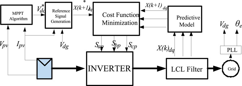
Figure 10. Block diagram of the model predictive control scheme for the storage-free grid connected PV system.
Consequently, the direct MPC scheme developed in Agoro et al. (2018b) for an H6 VSI is adopted in this sub-section for an H8 VSI. As such, applying (24) to the CT state space model of q-d expansions of (15) to (17) in Sub-Section VI A gives the predictive model in (25), which is used for closed loop predictive control.
where
As indicated in (115), in developing the dynamics of model predictive control of the DC-link voltage, the CT model of (18) is discretized by (24) to obtain (26). If it is assumed that the resistance of the filter is considered negligible, then the grid voltage,
Furthermore, in MPC, it is essential that the cost function(s) is (are) carefully selected. Therefore, in this sub-section, the primary control objectives of H8 VSI are to control the inverter side and grid side inductor current, regulate the filter capacitor voltage, and ensure a maximum power point tracking (MPPT) operation via DC-link voltage control. A secondary control objective can be set to maintain reduced switching losses during operation. Therefore, the compact control cost function used for the overall control scheme is given in (27).
The variables with ‘*’ index are the dynamically generated reference signals. The cost function contains seven different terms with four weights, which are
The direct MPC in the previous sub-section was simulated in the MATLAB/Simulink environment for two different categories. In the first category, the MPC was deployed on the H6 PV inverter system in Figure 7, and the results obtained are presented in Figures 11–16. The entire simulation was performed for a solar irradiance shown in Figure 11. The PV current in Figure 12A is seen to follow the path of the irradiance in Figure 11 and peaked at about 170 A. In Figure 12B, the DC-link voltage was maintained steady at 800 V. The q-axis and d-axis currents injected into the grid are shown in Figures 13, 14, respectively. The common-mode voltage and common-mode leakage current are shown in Figures 15, 16, respectively.
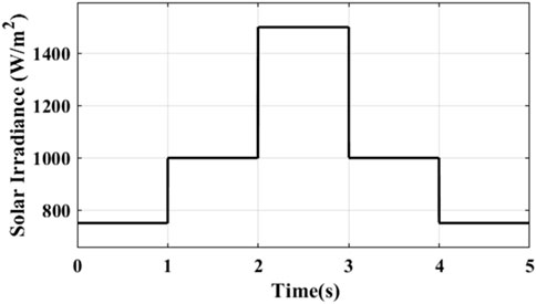
Figure 11. Solar irradiance.
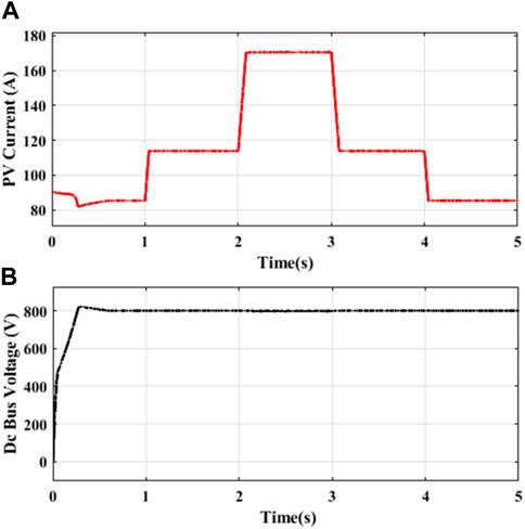
Figure 12. (A) PV current. (B) DC bus voltage.
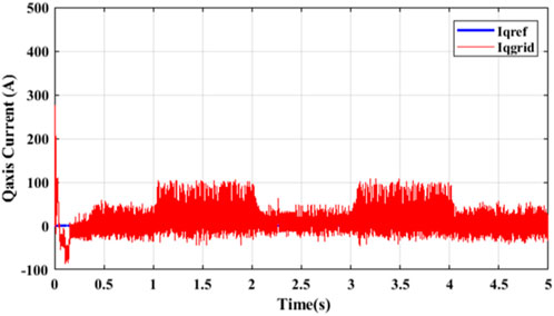
Figure 13. q-axis current into the grid from Figure 7.
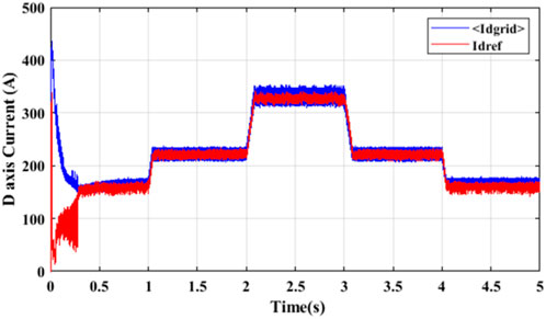
Figure 14. d-axis current into the grid from Figure 7.
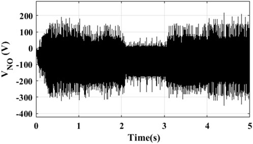
Figure 15. Common-mode voltage from Figure 7.

Figure 16. Common-mode leakage current from Figure 7.
Under the second category, the MPC was deployed on an H8 PV inverter system (Figure 17), and similar results obtained are presented in Figure 18–21. However, comparing previous Figures 16, 17 reveals significant reduction in the magnitudes of the common-mode voltage and common-mode leakage current. This is seen translating into improved quality of grid currents, as evident in q-axis current of Figure 18 with lower ripples than shown in Figure 14. Therefore, the inverse transformation of the q-d currents in Figures 18, 19, respectively, to the “a-b-c” reference frame as shown in Figure 22 reveals balanced three-phase current injection into the grid with negligible distortions.
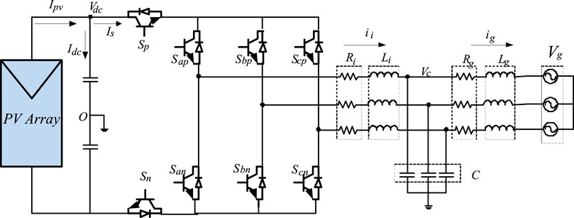
Figure 17. PV H8 inverter system.
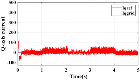
Figure 18. q-axis current into the grid from Figure 11.
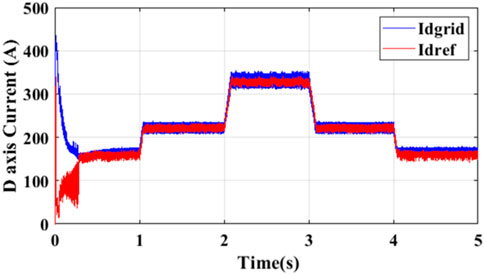
Figure 19. d-axis current into the grid from Figure 11.
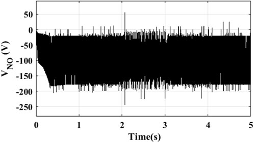
Figure 20. Common-mode voltage from Figure 11.
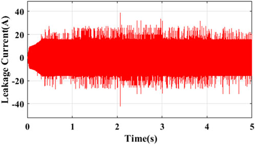
Figure 21. Common-mode leakage current from Figure 11.
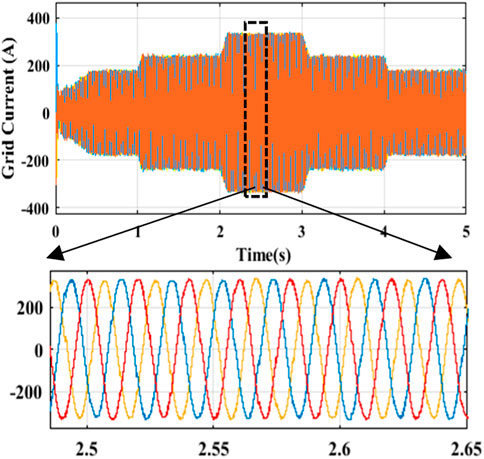
Figure 22. Three-phase current injection into the grid.
In Figure 23, the profile of line-to-line voltages in an 11-kV distribution grid in Nigeria with a steel mill connected at its PCC is shown. The steel mill uses both induction and arc furnaces. Evident in Figure 23 is the profound levels and frequency of voltage dip occurrence at such a distribution grid. If a similar load in the distribution grid exists in the 7-bus mini-grid given in Figure 1 and a stable voltage profile is desired, then robust contingency must be in place to support compensation whenever required. The 7-bus mini-grid may be modeled in ETAP as given in Figure 24. A fundamental technical solution for improved resiliency in such an isolated distribution grid is diversifying the power generation resources making up the distributed generation. This is evident in Figure 24 whereby the distributed generations (DGs) in Figure 1 are diversified as follows:
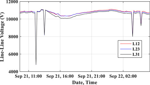
Figure 23. An 11-kV distribution grid in the NESI.
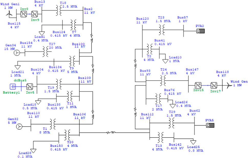
Figure 24. 7-bus mini-grid in ETAP.
DG1–Wind or mini-hydro or bio-fuel-based energy resources without storage.
DG2–Fossil fuel-based generation (spinning reserve).
DG3–Battery storage systems.
DG4–Fossil fuel-based generation.
DG5–Solar PV system with storage.
DG6–Wind or mini-hydro or bio-fuel based energy resources with storage.
DG7–Solar PV system without storage.
The nomenclature of the buses in the ETAP model of Figure 24 when compared to the hypothetical model in Figure 1 is given in Table 1.
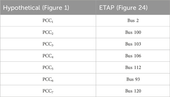
Table 1. Nomenclature of buses.
In Figure 24, the classical contingency strategy of N-1 is fulfilled by ensuring that fossil fuel-based generation is set aside as a spinning reserve for redundancy. Therefore, the fossil fuel-based generation does not always inject power into grid except when called upon for contingency. The other renewable energy resources are solar PV systems, wind, and/or mini-hydro energy resources. Battery storage systems are also connected to smoothen the intermittencies that may result from the renewable energy resources. Furthermore, critical loads are connected where steady power can always be guaranteed, such as buses 112 and 106. Buses 2 and 120 would not be considered for critical loads because whenever a fault occurs that isolates those buses, then the load connected gets completely isolated. However, a more comprehensive selection of buses suitable for steady power supply can be achieved via power flow studies. Moreover, the health management in sub-Section 4.3 will entail monitoring and management at the utilization/demand side to promote efficient and responsible utilization by power off-takers.
Control structures and strategies of autonomous distribution grids with embedded generation systems have been reviewed. The papers reviewed are from diverse climes of the world. The power infrastructure layouts in the papers are identified to have common control objectives, such as efficiency optimization. What really differs in all of the climes was in the availability of resources for distributed generation. Usually, technical, economical, and environmental factors dictated the choice of suitable technological outlay for stand-alone distribution grids. Therefore, the applicable control strategies reviewed can be adopted in the NESI to enhance mini-grid operations and promote green energy generation and utilization.
The distributed control system in hierarchical layers was observed to be generally preferred because of its robustness and easier scalability. MPC was seen to be applicable at the three hierarchical control layers. MPC on the PV H8 inverter system at the primary control layer was simulated, and the results revealed more reduction in common mode voltage and common mode leakage current than the conventional 2-level inverter.
AB: conceptualization and writing–original draft. AO: investigation, software, and writing–review and editing. AW: funding acquisition, investigation, and writing–review and editing. SA: conceptualization, methodology, and writing–review and editing. FO: project administration, supervision, and writing–review and editing. TS: funding acquisition, investigation, and writing–review and editing. IS: funding acquisition, investigation, and writing–review and editing. AA: funding acquisition, software, and writing–review and editing.
The author(s) declare that no financial support was received for the research, authorship, and/or publication of this article.
The authors acknowledge and appreciate the financial sponsorship and technical support given to this project by the Nigerian Electricity Regulatory Commission (NERC) and the University of Lagos. The authors deeply recognize the assistance given by Covenant University in all aspects of this research, especially the payment of the publication charges.
The authors declare that the research was conducted in the absence of any commercial or financial relationships that could be construed as a potential conflict of interest.
All claims expressed in this article are solely those of the authors and do not necessarily represent those of their affiliated organizations, or those of the publisher, the editors, and the reviewers. Any product that may be evaluated in this article, or claim that may be made by its manufacturer, is not guaranteed or endorsed by the publisher.
Abdulkareem, A., Oguntosin, V., Popoola, O., and Idowu, A. (2022). Modeling and nonlinear control of a quadcopter for stabilization and trajectory tracking. Hindawi J. Eng. 2022, 1–19. doi:10.1155/2022/2449901
Agoro, S., Balogun, A., Ojo, O., and Okafor, F. (2018a). “Control of a three-phase multi-string five-level inverter for grid integration of PV systems with unbalanced DC-link voltage,” in Proceedings for the 6th International Symposium on Power Electronics and Distributed Generation (PEDG) Systems, Charlotte North Carolina, USA, June 25–28, 2018.
Agoro, S., Balogun, A., Ojo, O., and Okafor, F. (2018b). “Direct model-based predictive control of a three-phase grid connected VSI for photovoltaic power evacuation,” in 2018 9th IEEE Int. Symp. Power Electron. Distrib. Gener. Syst. PEDG 2018, vol. 2, 1–6.
Ali, M. T., Zhou, D., Song, Y., Ghandhari, M., Harnefors, L., and Blaabjerg, F. (2020). Analysis and mitigation of SSCI in DFIG systems with experimental validation. IEEE Trans. Energy Convers. 35 (2), 714–723. doi:10.1109/tec.2019.2953976
Amoateng, D. O., Al Hosani, M., Elmoursi, M. S., Turitsyn, K., and Kirtley, J. L. (2018). Adaptive voltage and frequency control of islanded multi-microgrids. IEEE Trans. Power Syst. 33 (4), 4454–4465. doi:10.1109/tpwrs.2017.2780986
Anand, S., Fernandes, B. G., and Guerrero, J. M. (2013). Distributed control to ensure proportional load sharing and improve voltage regulation in low-voltage DC microgrids. IEEE Trans. Power Electron. 28 (4), 1900–1913. doi:10.1109/tpel.2012.2215055
Angirekula, B. N. V., and Ojo, O. (2014). “A Karnaugh mapping technique for the modeling of single phase multi string multilevel inverter,” in Applied Power Electronics Conference and Exposition (APEC), 2014 Twenty-Ninth Annual IEEE (IEEE).
Antoniadou-Plytaria, K. E., Kouveliotis-Lysikatos, I. N., Georgilakis, P. S., and Hatziargyriou, N. D. (2017). Distributed and decentralized voltage control of smart distribution networks: models, methods, and future research. IEEE Trans. Smart Grid 8 (6), 2999–3008. doi:10.1109/tsg.2017.2679238
Arcos-Aviles, D., Pascual, J., Marroyo, L., Sanchis, P., and Guinjoan, F. (2018). Fuzzy logic-based energy management system design for residential grid-connected microgrids. IEEE Trans. Smart Grid 9 (2), 530–543. doi:10.1109/tsg.2016.2555245
Arfeen, Z. A., Khairuddin, A. B., Larik, R. M., and Saeed, M. S. (2019). Control of distributed generation systems for microgrid applications: a technological review. Int. Trans. Electr. Energy Syst. 29 (9), 1–26. doi:10.1002/2050-7038.12072
Arnold, G. W. (2011). Challenges and opportunities in smart grid: a position article. Proc. IEEE 99 (6), 922–927. doi:10.1109/jproc.2011.2125930
Awelewa, A., Awosope, C. O. A., Abdulkareem, A., and Samuel, I. (2016). Nonlinear excitation control laws for electric power system stabilization. J. Eng. Appl. Sci. 11 (7), 1525–1531.
Awelewa, A., Popoola, O., Samuel, I., and Olajube, A. (2020). Comparison of nonlinear excitation controllers for power system stabilization. Int. J. Eng. Res. Technol. 13 (2), 320–333. doi:10.37624/ijert/13.2.2020.320-333
Aziz, T., Mhaskar, U. P., Saha, T. K., and Mithulananthan, N. (2013). An index for STATCOM placement to facilitate grid integration of der. IEEE Trans. Sustain. Energy 4 (2), 451–460. doi:10.1109/tste.2012.2227517
Balogun, A., Agoro, S., Okafor, F., Adetona, S., and Ojo, O. (2019). Common-mode voltage reduction and elimination in a space vector modulated three-phase five-level multistring inverter. IEEE PES/IAS PowerAfrica Conf. Power Econ. Energy Innov. Afr. Power Afr., 672–676. doi:10.1109/powerafrica.2019.8928909
Balogun, A., Ojo, O., and Okafor, F. (2015). “Compensation control of doubly-fed induction generator for wind energy conversion,” in IEEE International Electric Machines and Drives Conference (IEMDC), Coeur d’Alene, Idaho, USA, May 10–13, 2015, 1526–1531.
Balogun, A., Ojo, O., and Okafor, F. (2021). Efficiency optimization control of doubly-fed induction generator transitioning into shorted-stator mode for extended low wind speed application. IEEE Trans. Industrial Electron. 68 (12), 12218–12228. doi:10.1109/tie.2020.3037990
Balogun, A., Ojo, O., and Okafor, F. (2013). Decoupled direct control of natural and power variables of doubly-fed induction generator for extended wind speed range using feedback linearization. IEEE J. Emerg. Sel. Top. Power Electron. (JESTPE) 1 (4), 226–237. doi:10.1109/jestpe.2013.2283149
Bhandari, B., Lee, K. T., Lee, C. S., Song, C. K., Maskey, R. K., and Ahn, S. H. (2014). A novel off-grid hybrid power system comprised of solar photovoltaic, wind, and hydro energy sources. Appl. Energy 133, 236–242. doi:10.1016/j.apenergy.2014.07.033
Bidram, A., and Davoudi, A. (2012). Hierarchical structure of microgrids control system. IEEE Trans. Smart Grid 3 (4), 1963–1976. doi:10.1109/tsg.2012.2197425
Bidram, A., Davoudi, A., and Lewis, F. L. (2014). A multiobjective distributed control framework for islanded AC microgrids. IEEE Trans. Ind. Inf. 10 (3), 1785–1798. doi:10.1109/tii.2014.2326917
Bidram, A., Davoudi, A., Lewis, F. L., and Guerrero, J. M. (2013). Distributed cooperative secondary control of microgrids using feedback linearization. IEEE Trans. Power Syst. 28 (3), 3462–3470. doi:10.1109/tpwrs.2013.2247071
Boonchiam, P., and Mithulananthan, N. (2008). Diode-clamped multilevel voltage source converter based on medium voltage DVR. Int. J. power energy Syst. Eng. 1 (2), 62–67.
Buja, G. S., and Kazmierkowski, M. P. (2004). Direct torque control of PWM inverter-fed AC motors—a survey. IEEE Trans. Industrial Electron. 51 (4), 744–757. doi:10.1109/tie.2004.831717
Cai, H., Hu, G., Lewis, F. L., and Davoudi, A. (2016). A distributed feedforward approach to cooperative control of AC microgrids. IEEE Trans. Power Syst. 31 (5), 4057–4067. doi:10.1109/tpwrs.2015.2507199
Castilla, M., de Vicuña, L. G., and Miret, J. (2019). “Control of power converters in AC microgrids,” in n Microgrids design and implementation (Cham: Springer), 139–170.
Celanovic, N., and Boroyevich, D. (2001). A fast space-vector modulation algorithm for multilevel three-phase converters. IEEE Trans. industry Appl. 37 (2), 637–641. doi:10.1109/28.913731
Che, L., Khodayar, M. E., and Shahidehpour, M. (2014). Adaptive protection system for microgrids: protection practices of a functional microgrid system. IEEE Electrif. Mag. 2 (1), 66–80. doi:10.1109/mele.2013.2297031
Chen, F., Chen, M., Li, Q., Meng, K., Guerrero, J. M., and Abbott, D. (2016). Multiagent-based reactive power sharing and control model for islanded microgrids. IEEE Trans. Sustain. Energy 7 (3), 1232–1244. doi:10.1109/tste.2016.2539213
Chen, F., Chen, M., Li, Q., Meng, K., Zheng, Y., Guerrero, J. M., et al. (2017). Cost-based droop schemes for economic dispatch in islanded microgrids. IEEE Trans. Smart Grid 8 (1), 63–74. doi:10.1109/tsg.2016.2581488
Chen, G., Lewis, F. L., Feng, E. N., and Song, Y. (2015). Distributed optimal active power control of multiple generation systems. IEEE Trans. Ind. Electron. 62 (11), 7079–7090. doi:10.1109/tie.2015.2431631
Chen, M., Xiao, X., and Guerrero, J. M. (2018). Secondary restoration control of islanded microgrids with a decentralized event-triggered strategy. IEEE Trans. Ind. Inf. 14 (9), 3870–3880. doi:10.1109/tii.2017.2784561
Chu, C. C., and Iu, H. H. C. (2017). Complex networks theory for modern smart grid applications: a survey. IEEE J. Emerg. Sel. Top. Circuits Syst. 7 (2), 177–191. doi:10.1109/jetcas.2017.2692243
Chung, S. K. (2000). A phase tracking system for three phase utility interface inverters. IEEE Trans. Power Electron. 15 (3), 431–438. doi:10.1109/63.844502
Concari, L., Barater, D., Buticchi, G., Concari, C., and Liserre, M. (2016). H8 inverter for common-mode voltage reduction in electric drives. IEEE Trans. Ind. Appl. 52 (5), 4010–4019. doi:10.1109/tia.2016.2581763
Dang, D. Q., Choi, Y. S., Choi, H. H., and Jung, J. W. (2015). Experimental validation of a fuzzy adaptive voltage controller for three-phase PWM inverter of a standalone DG unit. IEEE Trans. Ind. Inf. 11 (3), 632–641. doi:10.1109/tii.2015.2416981
De Carne, G., Buticchi, G., Liserre, M., and Vournas, C. (2015). “Frequency-based overload control of smart transformers,” in 2015 IEEE Eindhoven PowerTech, Eindhoven, Netherlands, 1–5.
De Carne, G., Buticchi, G., Liserre, M., and Vournas, C. (2018). Load control using sensitivity identification by means of smart transformer. IEEE Trans. Smart Grid 9 (4), 2606–2615. doi:10.1109/tsg.2016.2614846
Dehkordi, N. M., Baghaee, H. R., Sadati, N., and Guerrero, J. M. (2019). Distributed noise-resilient secondary voltage and frequency control for islanded microgrids. IEEE Trans. Smart Grid 10 (4), 3780–3790. doi:10.1109/tsg.2018.2834951
Dehkordi, N. M., Sadati, N., and Hamzeh, M. (2017a). Distributed robust finite-time secondary voltage and frequency control of islanded microgrids. IEEE Trans. Power Syst. 32 (5), 3648–3659. doi:10.1109/tpwrs.2016.2634085
Dehkordi, N. M., Sadati, N., and Hamzeh, M. (2017b). Fully distributed cooperative secondary frequency and voltage control of islanded microgrids. IEEE Trans. Energy Convers. 32 (2), 675–685. doi:10.1109/tec.2016.2638858
Energy (2004). “Final report on the August 14, 2003 blackout in the United States and Canada: causes and recommendations,” in U.S.-Canada power system outage task force, tech. Rep. Available at: http://energy.gov/sites/prod/files/oeprod/DocumentsandMedia/BlackoutFinal-Web.pdf.
Faisal, M., Hannan, M. A., Ker, P. J., Hussain, A., Mansor, M. B., and Blaabjerg, F. (2018). Review of energy storage system technologies in microgrid applications: issues and challenges. IEEE Access 6, 35143–35164. doi:10.1109/access.2018.2841407
Fioriti, D., Giglioli, R., Poli, D., Lutzemberger, G., Vanni, A., and Salza, P. (2017). “Optimal sizing of a hybrid mini-grid considering the fuel procurement and a rolling horizon system operation,” in Conf. Proc. - 2017 17th IEEE Int. Conf. Environ. Electr. Eng. 2017 1st IEEE Ind. Commer. Power Syst. Eur. EEEIC/I CPS Eur. 2017.
Gao, X., De Carne, G., Liserre, M., and Vournas, C. (2017). “Voltage control by means of smart transformer in medium voltage feeder with distribution generation,” in 2017 IEEE Manchester PowerTech, Manchester, 1–6.
Golsorkhi, M. S., Shafiee, Q., Lu, D. D. C., and Guerrero, J. M. (2017). A distributed control framework for integrated photovoltaic-battery-based islanded microgrids. IEEE Trans. Smart Grid 8 (6), 2837–2848. doi:10.1109/tsg.2016.2593030
Guerrero, J. M., Chandorkar, M., Lee, T. L., and Loh, P. C. (2013a). Advanced control architectures for intelligent microgridspart i: decentralized and hierarchical control. IEEE Trans. Ind. Electron. 60 (4), 1254–1262. doi:10.1109/tie.2012.2194969
Guerrero, J. M., Loh, P. C., Lee, T. L., and Chandorkar, M. (2013b). Advanced control architectures for intelligent microgridsPart II: power quality, energy storage, and AC/DC microgrids. IEEE Trans. Ind. Electron. 60 (4), 1263–1270. doi:10.1109/tie.2012.2196889
Guo, F., Wen, C., Mao, J., Chen, J., and Song, Y. D. (2015). Distributed cooperative secondary control for voltage unbalance compensation in an islanded microgrid. IEEE Trans. Ind. Inf. 11 (5), 1078–1088. doi:10.1109/tii.2015.2462773
Haimo, V. (1986). Finite-time controllers. SIAM J. Contr. Optim. 24 (4), 760–770. doi:10.1137/0324047
Hatziargyriou, N. D., Jenkins, N., and Strbac, G. (2006). Microgrids-large scale integration of microgeneration to low voltage grids. CIGRE C6-309, 1–8.
Hava, A. M., Kerkman, R. J., and Lipo, T. A. (1999). Simple analytical and graphical methods for carrier-based PWM-VSI drives. IEEE Trans. Power Electron. 14 (1), 49–61. doi:10.1109/63.737592
Hazelton, J., Bruce, A., and MacGill, I. (2014). A review of the potential benefits and risks of photovoltaic hybrid mini-grid systems. Renew. Energy 67, 222–229. doi:10.1016/j.renene.2013.11.026
Hiskens, I. A., and Fleming, E. M. (2008). Control of inverter-connected sources in autonomous microgrids. Proc. Am. Control Conf., 586–590. doi:10.1109/acc.2008.4586555
Holmes, D. G., and Lipo, T. A. (2003) Pulse width modulation for power converters: principles and practice. IEEE Press, Wiley-Interscience, John Wiley and Sons, Inc.
Josep, M. (2017). Review on control of DC microgrids and multiple microgrid clusters aalborg universitet review on control of DC microgrids and multiple microgrid clusters. IEEE J. Emerg. Sel. Top. Power Electron. 5 (3), 928–948.
Jumani, T. A., Mustafa, M. W., Alghamdi, A. S., Rasid, M. M., Alamgir, A., and Awan, A. B. (2020). Swarm intelligence-based optimization techniques for dynamic response and power quality enhancement of AC microgrids: a comprehensive review. IEEE Access 8, 75986–76001. doi:10.1109/access.2020.2989133
Karugaba, S., Muetze, A., and Ojo, O. (2012). On the common-mode voltage in multilevel multiphase single-and double-ended diode-clamped voltage-source inverter systems. IEEE Trans. Ind. Appl. 48 (6), 2079–2091. doi:10.1109/tia.2012.2226223
Kumar, R., Ghatikar, G., Seethapathy, R., Sonavane, V. L., Khaparde, S. A., Yemula, P. K., et al. (2018). “Compendium of technical papers,” in 4th International Conference and Exhibition on Smart Grids and Smart Cities, Berlin, Germany, 20-24 May 2018.
Kumar, S., Verma, A. K., Hussain, I., Singh, B., and Jain, C. (2017). Better control for a solar energy system: using improved enhanced phase-locked loop-based control under variable solar intensity. IEEE Ind. Appl. Mag. 23 (2), 24–36. doi:10.1109/mias.2016.2600730
Laaksonen, H., Saari, P., and Komulainen, R. (2005). Voltage and frequency control of inverter based weak LV network microgrid. 2005 Int. Conf. Futur. Power Syst. 2005 (2), 6–11. doi:10.1109/fps.2005.204293
Lai, J., Lu, X., Yu, X., and Monti, A. (2019). Cluster-oriented distributed cooperative control for multiple AC microgrids. IEEE Trans. Ind. Inf. 15 (11), 5906–5918. doi:10.1109/tii.2019.2908666
Lasseter, R. H. (2002). “MicroGrids: a conceptual solution,” in 2002 IEEE Power Eng. Soc. Winter Meet. Conf. Proc. (Cat. No.02CH37309), vol. 1, New York, NY, USA, 27-31 January, 2002, 305–308.
Lasseter, R. H. (2011). Smart distribution: coupled microgrids. Proc. IEEE 99 (6), 1074–1082. doi:10.1109/jproc.2011.2114630
Lasseter, R. H., and Paigi, P. (2004). “Microgrid: a conceptual solution,” in 2004 IEEE 35th Annual Power Electronics Specialists Conference (IEEE Cat. No.04CH37551) 6, Aachen, Germany, 20-25 June 2004, 4285–4290.
Li, Q., Chen, F., Chen, M., Guerrero, J. M., and Abbott, D. (2016). Agent-based decentralized control method for islanded microgrids. IEEE Trans. Smart Grid 7 (2), 637–649.
Li, Q., Peng, C., Chen, M., Chen, F., Kang, W., Guerrero, J. M., et al. (2017). Networked and distributed control method with optimal power dispatch for islanded microgrids. IEEE Trans. Ind. Electron. 64 (1), 493–504. doi:10.1109/tie.2016.2598799
Liao, Y. H., and Lai, C. M. (2011). Newly-constructed simplified single-phase multistring multilevel inverter topology for distributed energy resources. IEEE Trans. Power Electron. 26 (9), 2386–2392. doi:10.1109/tpel.2011.2157526
Liserre, M., Blaabjerg, F., and Hansen, S. (2001). Design and control of an LCL-filter based three-phase active rectifier. Conf. Rec. - IAS Annu. Meet. IEEE Ind. Appl. Soc. 1 (C), 299–307.
Liu, W., Gu, W., Sheng, W., Meng, X., Wu, Z., and Chen, W. (2014a). Decentralized multi-agent system-based cooperative frequency control for autonomous microgrids with communication constraints. IEEE Trans. Sustain. Energy 5 (2), 446–456. doi:10.1109/tste.2013.2293148
Liu, W., Member, S., Gu, W., Sheng, W., Meng, X., and Chen, W. (2014b). Decentralized multi-agent system-based cooperative frequency control for autonomous microgrids with communication constraints. IEEE Trans. Sustain. Energy 5 (2 April), 446–456. doi:10.1109/tste.2013.2293148
Loh, P. C., Holmes, D. G., Fukuta, Y., and Lipo, T. A. (2002). “Reduced common mode carrier-based modulation strategies for cascaded multilevel inverters,” in Industry Applications Conference, 2002. 37th IAS Annual Meeting. Conference Record of the, vol. 3, Pittsburgh, Pennsylvania, USA, 13-18 October 2002 (IEEE).
Lovejoy, D. (1992). Electrification of rural areas by solar PV. Nat. Resour. Forum 16 (2), 102–110. doi:10.1111/j.1477-8947.1992.tb00555.x
Lu, X., Guerrero, J. M., Sun, K., Vasquez, J. C., Teodorescu, R., and Huang, L. (2013). Hierarchical control of parallel AC-DC converter interfaces for hybrid microgrids. IEEE Trans. Smart Grid 5 (2), 683–692. doi:10.1109/tsg.2013.2272327
Lu, X., Yu, X., Lai, J., Wang, Y., and Guerrero, J. M. (2018). A novel distributed secondary coordination control approach for islanded microgrids. IEEE Trans. Smart Grid 9 (4), 2726–2740. doi:10.1109/tsg.2016.2618120
Maes, J., and Melkebeek, J. A. (2000). Speed–sensorless direct torque control of induction motors using an adaptive flux observer. IEEE Trans. Industry Appl. 36 (3), 778–785. doi:10.1109/28.845053
Meng, L., Shafiee, Q., Member, S., and Trecate, G. F. (2017). Review on control of DC microgrids. IEEE J. Emerg. Sel. Top. Power Electron. 5 (3), 928–948.
Meng, W., Wang, X., and Liu, S. (2018). Distributed load sharing of an inverter-based microgrid with reduced communication. IEEE Trans. Smart Grid 9 (2), 1354–1364. doi:10.1109/tsg.2016.2587685
Mipoung, O. D., Lopes, L. A. C., and Pillay, P. (2014). Frequency support from a fixed-pitch type-2 wind turbine in a diesel hybrid mini-grid. IEEE Trans. Sustain. Energy 5 (1), 110–118. doi:10.1109/tste.2013.2273944
Moayedi, S., and Davoudi, A. (2016). Distributed tertiary control of DC microgrid clusters. IEEE Trans. Power Electron. 31 (2), 1717–1733. doi:10.1109/tpel.2015.2424672
Moayedi, S., and Davoudi, A. (2017). Unifying distributed dynamic optimization and control of islanded DC microgrids. IEEE Trans. Power Electron. 32 (3), 2329–2346. doi:10.1109/tpel.2016.2565517
Morstyn, T., Hredzak, B., and Agelidis, V. G. (2018). Control strategies for microgrids with distributed energy storage systems: an overview. IEEE Trans. Smart Grid 9 (4), 3652–3666. doi:10.1109/tsg.2016.2637958
Morstyn, T., Member, S., Hredzak, B., and Member, S. (2016). Control strategies for microgrids with distributed energy storage systems: an overview. IEEE Trans. Smart Grid 9 (4), 3652–3666. doi:10.1109/tsg.2016.2637958
Mujtaba, G., Rashid, Z., Umer, F., Baloch, S. K., Hussain, G. A., and Haider, M. U. (2020). Implementation of distributed generation with solar plants in a 132 kV grid station at layyah using ETAP. Int. J. Photoenergy 2020, 1–14. doi:10.1155/2020/6574659
Nabae, A., Takahashi, I., and Akagi, H. (1981). A new neutral-point-clamped PWM inverter. IEEE Trans. Ind. Appl. 1A-17 (5), 518–523. doi:10.1109/tia.1981.4503992
Narang, D., Ingram, M., Hoke, A., Narang, D., Ingram, M., and Hoke, A. (2020) Clause-by-Clause summary of requirements in IEEE standard 1547- 2018. Golden, CO (United States): National Renewable Energy Lab.NREL. (No. NREL/TP-5D00-75184).
Nasirian, V., Member, S., Moayedi, S., Member, S., and Davoudi, A. (2014). Distributed cooperative control of DC microgrids. IEEE Trans. Power Electron. 30 (4), 2288–2303. doi:10.1109/tpel.2014.2324579
Nasirian, V., Shafiee, Q., Guerrero, J. M., Lewis, F. L., and Davoudi, A. (2016). Droop-free distributed control for AC microgrids. IEEE Trans. Power Electron. 31 (2), 1600–1617. doi:10.1109/tpel.2015.2414457
NERC (2024). Niegerian electricity regulatory commission. Available at: www.nerc.gov.ng.
Nik Idris, N. R., and Mohamed Yatim, A. H. (2004). Direct torque control of induction machines with constant switching frequency and reduced torque ripple. IEEE Trans. Power Electron. 51 (4), 758–767. doi:10.1109/tie.2004.831718
Ojo, O., and Kshirsagar, P. (2003). The generalized discontinuous PWM modulation scheme for three-phase voltage source inverters. IECON Proc. Ind. Electron. Conf. 2, 1629–1636.
Olivares, D. E., Mehrizi-Sani, A., Etemadi, A. H., Canizares, C. A., Iravani, R., Kazerani, M., et al. (2014). Trends in microgrid control. IEEE Trans. Smart Grid 5 (4), 1905–1919. doi:10.1109/tsg.2013.2295514
Pedrasa, M. A., Spooner, T., Pedrasa, M. A., and Spooner, T. (2006). A survey of techniques used to control microgrid generation and storage during island operation. AUPEC 1, 15.
Perlack, R. D., Petrich, C. H., and Schweitzer, S. (1988). A comparison of decentralized minigrids and dispersed diesels for irrigation pumping in sahelian africa. Nat. Resour. Forum 12 (3), 235–242. doi:10.1111/j.1477-8947.1988.tb00823.x
Poddar, G., and Ranganathan, V. T. (2004). Direct torque and frequency control of double-inverter-fed slip-ring induction motor drive. IEEE Trans. Industrial Electron. 51 (6), 1329–1337. doi:10.1109/tie.2004.837897
Qu, Z., Wang, J., and Hull, R. A. (2008). Cooperative control of dynamical systems with application to autonomous vehicles. IEEE Trans. Autom. Contr. 53 (4), 894–911. doi:10.1109/tac.2008.920232
Rahim, N. A., and Selvaraj, J. (2010). Multistring five-level inverter with novel PWM control scheme for PV application. IEEE Trans. industrial Electron. 57 (6), 2111–2123. doi:10.1109/tie.2009.2034683
Rahimi, R., Farhangi, S., Farhangi, B., Moradi, G. R., Afshari, E., and Blaabjerg, F. (2018). H8 inverter to reduce leakage current in transformerless three-phase grid-connected photovoltaic systems. IEEE J. Emerg. Sel. Top. Power Electron. 6 (2), 910–918. doi:10.1109/jestpe.2017.2743527
Rasheduzzaman, M., and Kimball, J. W. (2019). Modeling and tuning of an improved delayed-signal-cancellation PLL for microgrid application. IEEE Trans. Energy Convers. 34 (2), 712–721. doi:10.1109/tec.2018.2880610
Rocabert, J., Luna, A., Blaabjerg, F., and Rodriguez, P. (2012). Control of power converters in AC microgrids. IEEE Trans. power Electron. 27 (11), 4734–4749. doi:10.1109/tpel.2012.2199334
Sahoo, S. K., Member, S., and Sinha, A. K. (2017). Control techniques in AC, dc, and hybrid AC–DC microgrid: a review. IEEE J. Emerg. Sel. Top. Power Electron. 6 (2), 738–759. doi:10.1109/jestpe.2017.2786588
Sen, S., and Kumar, V. (2018). Microgrid control: a comprehensive survey. Annu. Rev. Control 45, 118–151. doi:10.1016/j.arcontrol.2018.04.012
Shafiee, Q., Nasirian, V., Vasquez, J. C., Guerrero, J. M., and Davoudi, A. (2018). A multi-functional fully distributed control framework for AC microgrids. IEEE Trans. Smart Grid 9 (4), 3247–3258. doi:10.1109/tsg.2016.2628785
She, X., Yu, X., Wang, F., and Huang, A. Q. (2014). Design and demonstration of a 3.6kV-120V/10KVA solid state transformer for smart grid application. Conf. Proc. - IEEE Appl. Power Electron. Conf. Expo.-APEC 29 (8), 3982–3996. doi:10.1109/tpel.2013.2293471
Sheikh, A., Youssef, T., and Mohammed, O. (2017). “AC microgrid control using adaptive synchronous reference frame PLL,” in IEEE green technol. Conf., 46–51.
Shrestha, A., Rajbhandari, Y., Khadka, N., Bista, A., Marahatta, A., Dahal, R., et al. (2020). Status of micro/mini-grid systems in a himalayan nation: a comprehensive review. IEEE Access 8, 120983–120998. doi:10.1109/access.2020.3006912
Singh, M., Lopes, L. A. C., and Ninad, N. A. (2015). Grid forming Battery Energy Storage System (BESS) for a highly unbalanced hybrid mini-grid. Electr. Power Syst. Res. 127, 126–133. doi:10.1016/j.epsr.2015.05.013
Sun, Q., Guerrero, J. M., Jing, T., Quintero, R., and Yang, J. C. V. (2016). An islanding detection method by using frequency positive feedback based on FLL for single-phase microgrid. IEEE Trans. Smart Grid 8 (4), 1821–1830. doi:10.1109/tsg.2015.2508813
Surprenant, M., Hiskens, I., and Venkataramanan, G. (2011). “Phase locked loop control of inverters in a microgrid,” in IEEE Energy Convers. Congr. Expo. Energy Convers. Innov. a Clean Energy Futur. ECCE 2011, Proc., September, 2011, 667–672. doi:10.1109/ecce.2011.6063833
Tahir, M., and Mazumder, S. K. (2015). Self-Triggered communication enabled control of distributed generation in microgrids. IEEE Trans. Ind. Inf. 11 (2), 441–449.
Unamuno, E., and Barrena, J. A. (2015). Hybrid ac/dc microgrids - Part II: review and classification of control strategies. Renew. Sustain. Energy Rev. 52, 1123–1134. doi:10.1016/j.rser.2015.07.186
Vasquez, J. C., Guerrero, J. M., Savaghebi, M., and Teodorescu, R. (2012). Modeling, analysis, and design of stationary reference frame droop controlled parallel three-phase voltage source inverters. IEEE Trans. Industrial Electron. 60 (4), 1271–1280. doi:10.1109/tie.2012.2194951
Wang, X., Taul, M. G., Wu, H., Liao, Y., Blaabjerg, F., and Harnefors, L. (2020). Grid-synchronization stability of converter-based resources—an overview. IEEE Open J. Industry Appl. 1, 115–134. doi:10.1109/ojia.2020.3020392
Worldbank (2024). openknowledge. Available at: www.openknowledge.worldbank.org.
Wu, X., and Shen, C. (2017). Distributed optimal control for stability enhancement of microgrids with multiple distributed generators. IEEE Trans. Power Syst. 32 (5), 4045–4059. doi:10.1109/tpwrs.2017.2651412
Wu, X., Shen, C., and Iravani, R. (2018). A distributed, cooperative frequency and voltage control for microgrids. IEEE Trans. Smart Grid 9 (4), 2764–2776. doi:10.1109/tsg.2016.2619486
Xiang, Y., Pei, X., Wang, M., Shi, P., and Kang, Y. (2019). An improved H8 topology for common-mode voltage reduction. IEEE Trans. Power Electron. 34 (6), 5352–5361. doi:10.1109/tpel.2018.2870039
Xin, H., Qu, Z., Seuss, J., and Maknouninejad, A. (2011). A self-organizing strategy for power flow control of photovoltaic generators in a distribution network. IEEE Trans. Power Syst. 26 (3), 1462–1473. doi:10.1109/tpwrs.2010.2080292
Xu, Y., Sun, H., Gu, W., Xu, Y., and Li, Z. (2019). Optimal distributed control for secondary frequency and voltage regulation in an islanded microgrid. IEEE Trans. Ind. Inf. 15 (1), 225–235. doi:10.1109/tii.2018.2795584
Yao, W., Hu, H., and Lu, Z. (2008). Comparisons of space-vector modulation and carrier-based modulation of multilevel inverter. IEEE Trans. Power Electron. 23 (1), 45–51. doi:10.1109/tpel.2007.911865
Yazdanian, M., Member, G. S., and Mehrizi-sani, A. (2014). Distributed control techniques in microgrids. IEEE Trans. Smart Grid 5 (6), 2901–2909. doi:10.1109/tsg.2014.2337838
Zhao, Z., Yang, P., Guerrero, J. M., Xu, Z., and Green, T. C. (2016). Multiple-time-scales hierarchical frequency stability control strategy of medium-voltage isolated microgrid. IEEE Trans. Power Electron. 31 (8), 5974–5991. doi:10.1109/tpel.2015.2496869
Zhi, D., and Xu, L. (2007). Direct power control of DFIG with constant switching frequency and improved transient performance. IEEE Trans. Energy Convers. 22 (1), 110–118. doi:10.1109/tec.2006.889549
Keywords: distributed control system, hierarchical control system, model predictive control, H8 2-level voltage source inverter, stand-alone mini-grid
Citation: Balogun A, Olajube A, Awelewa A, Agoro S, Okafor F, Sanni T, Samuel I and Ajilore A (2024) Control strategies in enhanced stand-alone mini-grid operations for the NESI–an overview. Front. Energy Res. 12:1397482. doi: 10.3389/fenrg.2024.1397482
Received: 07 March 2024; Accepted: 10 May 2024;
Published: 13 June 2024.
Edited by:
Mufutau Adekojo Waheed, Federal University of Agriculture, NigeriaReviewed by:
Kenneth E. Okedu, Melbourne Institute of Technology, AustraliaCopyright © 2024 Balogun, Olajube, Awelewa, Agoro, Okafor, Sanni, Samuel and Ajilore. This is an open-access article distributed under the terms of the Creative Commons Attribution License (CC BY). The use, distribution or reproduction in other forums is permitted, provided the original author(s) and the copyright owner(s) are credited and that the original publication in this journal is cited, in accordance with accepted academic practice. No use, distribution or reproduction is permitted which does not comply with these terms.
*Correspondence: Ayokunle Awelewa, YXlva3VubGUuYXdlbGV3YUBjb3ZlbmFudHVuaXZlcnNpdHkuZWR1Lm5n
Disclaimer: All claims expressed in this article are solely those of the authors and do not necessarily represent those of their affiliated organizations, or those of the publisher, the editors and the reviewers. Any product that may be evaluated in this article or claim that may be made by its manufacturer is not guaranteed or endorsed by the publisher.
Research integrity at Frontiers
Learn more about the work of our research integrity team to safeguard the quality of each article we publish.