 Yan Tian
 Bo Huang
- Guangzhou Power Utility, Guangdong Power Grid Co., Ltd., Guangzhou, China
To provide inertia support to the power grid, the grid side frontend DC/AC inverter of the bidirectional electric vehicle (EV) charging facilities can use the virtual synchronous generator (VSG) control in its grid-side DC/AC converter. However, the existing VSG control cannot actually realize the inertia support due to the limitations of the existing cascaded power converters control structure of the bidirectional EV charger. This paper proposes a new control infrastructure for VSG based bi-directional EV charging facilities. The proposed control instantaneously tracks the inertial supporting surge power by DC/DC so as to stabilize the DC bus voltage. Meanwhile, the droop coefficient based power values are also fed forward to DC/DC controls to support grid frequency control over a larger time scale. Finally, the experiment results show that the proposed method improves the DC bus voltage stability of the EV charger while allowing the EV to participate in the power system frequency regulation, which is a key feature of the Vehicle to Grid applications.
1 Introduction
In a power system, inertial support refers to the power system’s frequency stability under external load disturbances. Namely, it comes from the rotor inertia of the synchronous generators. The kinetic energy stored in the inertia of synchronous generators plays a crucial role in ensuring the stability of a power system’s voltage and frequency during load disturbances. However, as renewable energy sources penetrate more into the power grids, the large-scale power electronic converters tied to the grid have resulted in a gradual decline in the percentages of traditional synchronous generators. Consequently, this leads to a decrease in overall system inertia (Zhou et al., 2022a)- (Zhong and Weiss, 2011). This reduction in inertia leads to an increased rate of frequency variation, posing a risk of exceeding the established grid standards. Therefore, there is an urgent need for more grid-friendly power electronic converters.
The virtual synchronous generator (VSG) control for grid-tied inverters, as introduced in references (Zhu et al., 2016) – (Fujita et al., 2022), presents the approach to control the output voltage command of a converter with closed-loop. This method utilizes the same set of mathematical models of a generator to obtain the output voltage command. Thereby, the power electronic converter is controlled as a voltage-source with inertia to slow down the frequency variation, offering inertia support to the microgrid and smart grid applications.
Specifically, the bi-directional electric vehicle (EV) charging facilities are gaining popularity and percentage in the power grid, as the interactive interface between the electric vehicles and the power grid (Macioszek, 2019a; Macioszek, 2019b; Sierpiński and Macioszek, 2020; Macioszek, 2021). First, the EV charger is a flexible load, which can be controlled to have certain demand-side response capability, and certain inertia and damping characteristics are also incorporated to mitigate the impact of the charger load on the grid (Jiang et al., 2014a; Shuai et al., 2016; Zhong, 2017; Fang et al., 2019; Pan et al., 2020) Meanwhile, the bi-directional EV charging facilities are also effectively another embodiment of the distributed sources in the grid, as its grid side is a typical 3-phase DC/AC inverter, running the current regulated control as other renewable sources power converters. Obviously, the same need for a more grid-friendly power electronic converter exists for the bi-directional EV charging facilities. In (Jiang et al., 2014b), a two-stage structure for the EV charger with VSG control is proposed. Herein, the grid voltage is first rectified into 600V DC voltage in the first stage, and a high-power isolated DC/DC circuit with wide voltage output range is used in the second stage. The grid-side AC/DC converter utilizes VSG control. Paper (Shan et al., 2019) also applied VSG to the three-phase inverter of the DC rapid charger, the EV DC fast charger based on VSG technology is claimed to have inertia and damping power oscillation characteristics to grid voltage and frequency disturbances as well as large-capacity load throwing. In (Yang and Hu, 2022), a strategy is proposed that treats electric vehicles and chargers as equivalent to a synchronous generator operating in four quadrants, expecting the capability to automatically regulate the frequency and voltage of the power grid. One proposed solution involves a two-stage structure for an EV charger utilizing VSG for grid-side AC/DC converter control (Jiang et al., 2014a; Shan et al., 2019; Kim et al., 2022; Wang et al., 2023; Sun et al., 2023; Zhou et al., 2022b; Zhang et al., 2016; Liu et al., 2016; Jongudomkarn, 2021), ensuring low harmonics in the grid current. Another application of VSG technology is in the three-phase controlled rectifier of DC fast chargers (Yang and Hu 2022). This configuration claims the inertia and damping characteristics in response to grid voltage and frequency disturbances and large-capacity load variations.
However, applying VSG control to the bi-directional EV charging facilities is not simply replacing the grid-side inverter current-regulated control with the VSG control, as done by the prior literatures (Cui et al., 2016; Zhang et al., 2022). The cascaded DC/DC converter and its control should be modified as a whole. Otherwise, the inertia support will not be achieved in practice. First of all, inertia support means that after the grid frequency drops, the corresponding virtual inertia of the grid-side VSG control will produce instantaneous power output to the grid. As for the VSG based grid-tied inverter directly powered by the battery sources, it can instantaneously follow the power demand. However, for VSG based bidirectional EV chargers, the grid side inverter VSG control has an outer closed loop to regulate a stable DC bus voltage, while the DC/DC converter controls the EV charging/discharging power and current (Ganne and Sahu, 2024). Therefore, transient inertia support power on the grid side inverter would disrupt the dynamic power balance of the dc bus, resulting in a sudden dip in the DC bus voltage Vdc. The outer Vdc closed loop will then generate a power command that offsets the inertia support power value, bringing the VSG power back to the value equal to the DC/DC charging power. Therefore, the VSG based bidirectional EV chargers cannot really achieve the inertia support in practice. Secondly, also due to the outer DC bus voltage control loop of the VSG control, the VSG based bidirectional EV chargers cannot really participate in grid frequency regulation. As the grid frequency drops, the power generated by the droop coefficient D of the VSG will reduce the power of the VSG as a load, and even feed back to the grid when the frequency deviation reaches a certain level, thereby participating in the frequency regulation of the grid. However, the closed-loop DC bus voltage control will cancel out the frequency regulation power.
The paper proposes to instantaneously replenish this inertial support instantaneous power deficit by drawing out the signals from the power feedback channel and the droop (damping) coefficient feedback channel inside the VSG control model and feeding forward them. Thus, the DC voltage outer loop does not generate additional power commands to offset the inertia support and the frequency regulation power of the VSG. Finally, The advantages of the proposed control method over the existing VSG based bidirectional EV chargers control architecture were verified using both simulations and experiments. As a result, the paper successfully addresses the issue that the existing VSG control cannot actually realize the inertia support due to the limitations of the existing cascaded power converters control structure of the bidirectional EV charger.
The rest of the paper is organized as follows. In Section 2, the bidirectional charger grid-side VSG model is introduced. In Section 3, the existing methods are first investigated and the limitations of the existing control architecture of EV charger is presented. Then, the new control infrastructure for VSG based bi-directional EV charging facilities is proposed and comprehensive parametric design is presented. In Section 4, comparative experiment results are presented. Finally, Section 5 concludes the paper.
2 Bidirectional charger grid-side VSG model
The VSG control block diagram is shown in Figure 1, where Vdc is the DC side voltage, i1, i2 are the inverter side current and output side current respectively; uC is the capacitor voltage; Lf, Cf are the inverter side inductance and filter capacitor, Zline indicates line impedance between inverter and PCC access point, mainly resistive; line impedance is often small, generally can be approximated as the PCC point and capacitor voltage is the same. The controller of the VSG mainly consists of a power control loop and a voltage/current control loop.
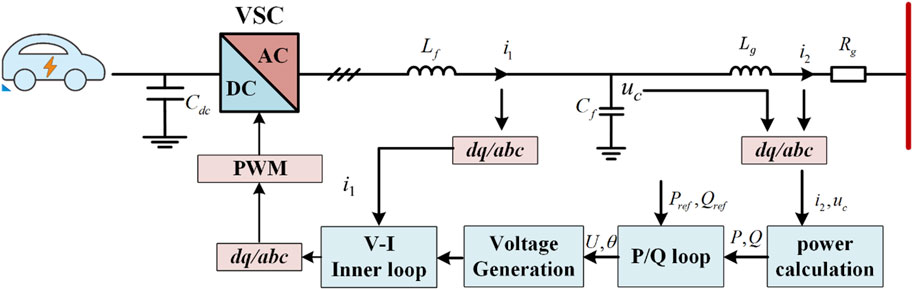
Figure 1. Virtual synchronous generator control block diagram.
In Figure 1, the active power command (Pref) and reactive power command (Qref) are utilized. The primary objective of VSG control is to generate an output voltage that encompasses both voltage magnitude and phase angle. A voltage-current inner loop is employed to adjust the value of E in order to track the reference voltage value (Uref). The inner loop typically has a higher bandwidth compared to the power outer loop. This is due to the fact that the time scale of decoupling and synchronization mainly depend on the power outer loop. Consequently, it can be regarded as a unified element that exhibits ideal output voltage tracking accuracy, with the VSG acting as the voltage source responsible for voltage control.
Traditional virtual synchronous generators (Tra-VSG) are implemented by simulating the rotation equations of actual synchronous generators, and their core control equations are shown in (Equation 1):
where J denotes the virtual rotational inertia, D is the damping coefficient, Pset and Pout are the command and output values of active power, and ωm and ωref denote the VSG output angular frequency and reference angular frequency.
Meanwhile, the Tra-VSG can simulate the generator’s excitation regulator to control the excitation current and internal electric potential to maintain the constant end voltage in order to improve the stability of voltage control. The paper uses the output reactive power as a reference for droop integral control, so the control equation of its reactive power control loop is shown as (Equation 2):
where Uref refers to the voltage command at the output, Dq refers to the reactive power droop control factor, K refers to the gain of the integral controller, Un refers to the output voltage rating, Uout refers to the output voltage sampling value, Qset refers to the reactive power command value, and Qout refers to the actual output reactive power. Figure 2 gives the VSG power loop diagram.
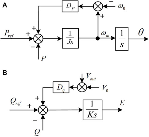
Figure 2. VSG power control loop. (A) active power loop.(B) reactive power loop.
The small signal expression of VSG can be derived from the equation of motion of a traditional synchronous generator and the instantaneous power theory, as depicted in Equation 3. By linearizing this power equation, the small-signal model of the output power is obtained, as shown in Equation 4. This model incorporates various factors that impact the active and reactive power, including the capacitor voltage E, the grid voltage amplitude Ug, and the power angle. Unlike previous models that neglected the coupling between active and reactive power, this model accounts for the coupling term, making it more accurate and comprehensive than earlier small-signal models of the virtual synchronous generator.
In the provided system, the following transfer functions can be defined:
Gδ2P: Transfer function from the power angle difference between the VSG and the grid to the output active power.
GE2P: Transfer function from the output voltage to the output active power.
GU2P: Transfer function from the grid voltage to the output active power.
Gδ2Q: Transfer function from the power angle difference between the VSG and the grid to the output reactive power.
GE2Q: Transfer function from the voltage at the output of the VSG to the output reactive power.
GU2Q: Transfer function from the grid voltage to the output reactive power.
These transfer functions represent the relationships between the respective inputs and outputs, providing insight into how changes in the power angle difference, output voltage, and grid voltage affect the output active and reactive powers of the VSG system.
where ∆P and ∆Q is the small signal model of the output active power and reactive power respectively, Ubus is the grid voltage amplitude, θg is the phase of the grid voltage, δ0 is the steady state power angle, ∆E is the small signal model of the output voltage amplitude of VSG, ∆δ is the small signal model of the power angle, ∆Ubus is the small signal model of the grid voltage amplitude.
According to the provided information, the specific expressions for the transfer functions mentioned in (Equation 5) are not given. However, based on the context, it can be understood that the small signal model of the VSG, considering the coupling of reactive power, can be derived. This model, as illustrated in Figure 3, includes the VSG controller, which is a component of the active and reactive power control loops depicted in Figure 1. Additionally, the power transfer model in Figure 3 represents the physical model of the system, encompassing the voltage and current dual loops, as well as the entire inverter.
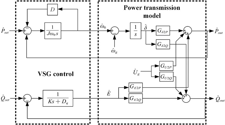
Figure 3. The complete VSG small signal model.
Based on (Equations 3, 4), it’s clear that the small signal model for the VSG, which incorporates the reactive power coupling, can be formulated. in Figure 3, incorporates the VSG controller. This controller is a part of the control loops for both active and reactive power, as shown in Figure 1. Moreover, the power transfer model depicted in Figure 3 outlines the physical structure of the system, the exact formulas for the transfer functions referenced in (5).
3 New controls proposal by analysing of the existing methods
3.1 The existing control method
As shown in Figure 4, the existing VSG based bi-directional EV charger control architecture uses VSG based AC/DC to regulate the dc bus voltage, and DC/DC to regulate the charging and discharging power. In this control method, the EV battery power is controlled by DC/DC closed loop; VSG control requires an additional layer of DC bus voltage control outer loop, i.e., the VSG power command of the AC/DC converter comes from the DC bus voltage control outer loop.
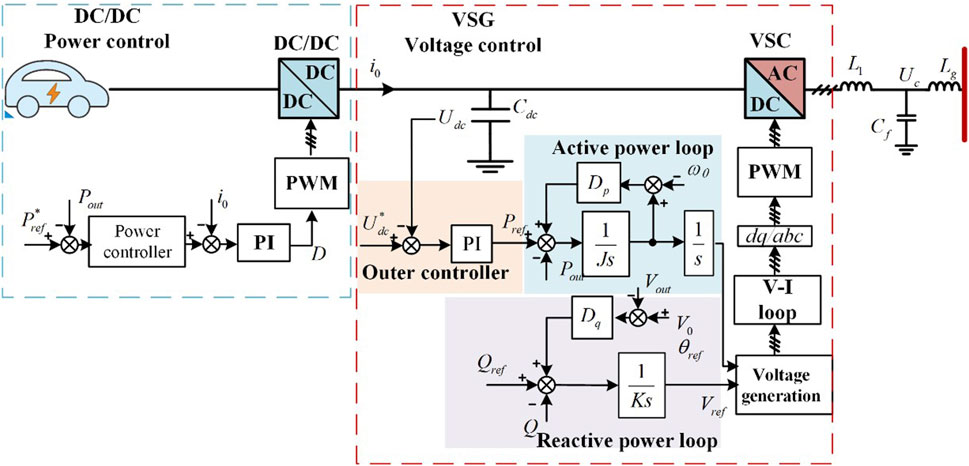
Figure 4. Existing VSG based directional EV charger control method.
3.2 Limitations of the existing architecture
Although there are some related papers about the existing control method, it is practically impossible to realize the grid inertia support and participation in frequency regulation.
Firstly, as for the momentary power output of the VSG inertia support after a temporary drop in the grid frequency, a VSG directly powered by the energy storage battery pack can assume this instantaneous power. However, for a VSG bi-directional EV charger, this instantaneous power transient on the grid side breaks the dynamic power balance between the AC/DC and the DC/DC, which will cause a sudden dip of Vdc in the initial transient. Subsequently, the closed loop Vdc control will gradually generate a power command to offset this inertial support power, making the VSG power equal to the DC/DC charging power. Thus, the existing VSG bi-directional EV charger can not actually provide the grid inertia support in practice.
Secondly, also due to the outer DC bus voltage control loop of the VSG control, the VSG based bidirectional EV chargers cannot really participate in grid frequency regulation. As the grid frequency drops, the power generated by the droop coefficient D of the VSG will reduce the power of the VSG as a load, and even feed back to the grid when the frequency deviation reaches a certain level, thereby participating in the frequency regulation of the grid. However, the closed-loop dc bus voltage control will cancel out the frequency regulation power.
According to the above analysis, the existing control method cannot realize the grid inertia support and grid frequency regulation.
3.3 The proposed method
The proposed control method for the VSG based bi-directional EV charger is illustrated in Figure 5.
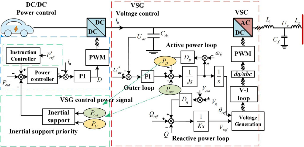
Figure 5. The proposed control method for the VSG based bi-directional EV charger.
In order to achieve grid inertial support under sudden grid load change conditions and to further participate in grid frequency regulation, the paper proposes that the VSG internal PD and Pout signals be used as the feedforward branches to the DC/DC power command. Thus, when the system has a temporary drop in grid frequency, the resulting VSG instantaneous inertia support power can be fed forward to the DC/DC power command. Then, the DC/DC converter can quickly follow the power change to maintain the power balance and prevent the significant dip in the dc bus voltage. Next, for a longer time scale of the transient, by feeding forward the power PD signal to the DC/DC power command, the power on the DC/DC side is also synchronized with the frequency regulation power on the VSG side.
Additionally, the proposed control architecture includes a new command controller as illustrated in Figure 6 to get the final command to DC/DC from the PD and Pout feedforward signals. This controller also regulates the slope of the charging power command, thereby mitigating the impact of transient changes in the charging side power on the voltage of the DC capacitor (Cdc). First, the output active power Pout of the VSG is passed through a high-pass filter as shown in (Equation 6).
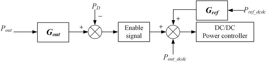
Figure 6. Control block diagram of inertial support controller.
The high-pass filter Gout allows the power command of the DC/DC controller to track the transient inertia supporting power as the grid frequency changes abruptly, so as to avoid the dc bus voltage dip. Meanwhile, the high-pass filter behaves as a disconnected state in the steady state, when the output active power is determined by the EV charging and discharging power with the frequency regulation power PD.
As for the charge/discharge power command, a low-pass filter is applied to the charge/discharge command to mitigate the adverse effects on the DC bus voltage. The expression describing this filtering process is depicted as Equation 7
With the proposed method, the VSG based bidirectional EV charger can effectively respond to grid frequency variations and actively participate in the primary frequency regulation, thereby contributing to the stability and performance of the power system.
3.4 Controller design
The parameters of the proposed control as in Figure 5 are designed subsequently. As the DC/DC part is using simple PI controls, its tunings process is not discussed here, while the grid inertia support capability of the bi-directional charger is studied here for stability analysis and controller tuning.
Using the small-signal equivalent circuit model of the active loop, the relationship between the output active power and the output angular frequency is derived. At this time, the value of Pref is 0, and the transfer function can be obtained as Equation 10
When the system reaches a stable state, s = 0. At this time, Δωm = ΔP/Dp. From the equation, it can also be seen that the value of Dp affects the magnitude of the angular frequency. The value of Dp is the smallest under no-load conditions and the largest under full-load conditions. During this process, it is necessary to ensure that the maximum deviation of the angular frequency is less than the allowable value, i.e.,
From this, it can be seen that as the grid frequency fluctuates, the active power output of the VSG will also be affected. If the damping coefficient Dp is too large, this impact will be amplified, so the value of Dp should be slightly greater than the critical value. Additionally, this equation reflects the function of the VSG in the power system, similar to primary frequency regulation.
When the load power suddenly changes, the output cannot change abruptly but can only gradually change according to an exponential rule. Therefore, the VSG supports the grid in the face of power fluctuations, effectively reducing the rate of change of the output grid frequency. Assuming a sudden load step up to the rated power, the maximum rate of change of the grid frequency can be calculated using the differentiation theorem as Equation 11
From the above equation, it can be observed that the maximum rate of change of the grid frequency in the VSG system is related to the power command and the virtual inertia. The smaller the virtual inertia, the greater the rate of change of the grid frequency. When there are significant changes in the VSG loads, especially during large load steps, significant rate of change in the grid frequency will be observed. Therefore, constraints need to be applied to the virtual inertia as
With all the steps above, the bode diagram of Equation 8 is plotted in Figure 7. A phase margin of 76.6 is observed, indicating a stable system.
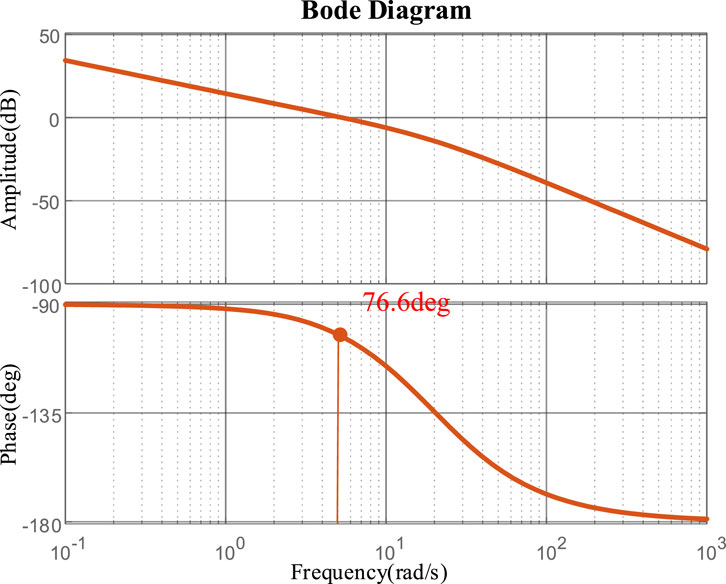
Figure 7. Bode diagram of designed controller.
As in prior discussion, the inertia support controller parameters design is to accord to the frequency deviation of the power grid. In the national standard GB/T 15945-2008 in China, the frequency deviation limit is given, and it is clearly required that the frequency deviation limit under the normal operation conditions of the power system does not exceed 0.2 Hz, and in small capacity power systems, the difference shall not exceed 0.5 Hz, which applies to our simulation and experimental system. Then, according to Equations 9, 12, the controller parameters of the target system have been designed as in Table 1. These parameters are used in both simulations and experiments.
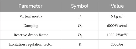
Table 1. Bi-directional charger inertia support related controls parameters.
4 Simulation and experimental validation
In order to verify the superiority of the proposed control method over existing method, a simulation model of the bi-directional charger is built on MATLAB platform. Moreover, a large scale prototype of bi-directional EV charger was built in the laboratory as in Figure 8. Herein, one channel of cascaded AC/DC and DC/DC converters are used for the experiments. This cascaded power conversion unit output is connected to the charger terminal as in Figure 8, where it is shown that a BYD Dolphin EV is plugged in.
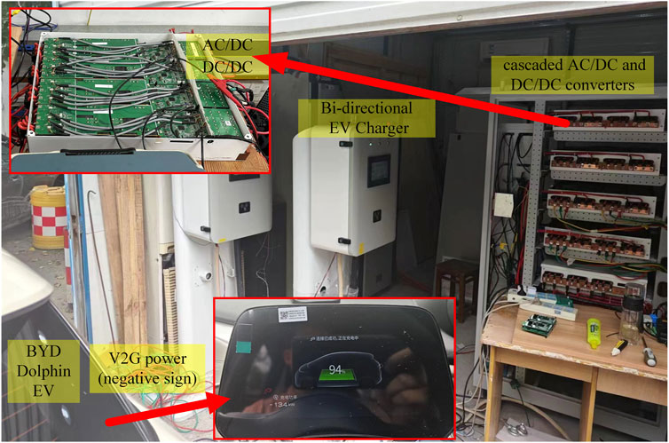
Figure 8. Experimental platform.
The grid-side AC/DC converter is an IGBT-based three-bridge converter with an LC filter. The AC side of the charger is connected to an external 1.5 mH inductor to simulate the line impedance; the control program is realized by TI-TMS320F28335 DSP, using CAN communication to realize the data transmission between DSP and Labview host computer. An oscilloscope is used to collect voltage and current signals. At the same time, the host computer obtains the real-time signals, such as frequency, power, etc. The parameters of the experimental platform is shown in Table 2.
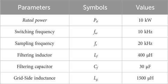
Table 2. Parameters of the experimental platform.
As an important part of the overall system, the BYD Dolphin EV has adopt Blade Battery’s first-generation 135Ah lithium iron phosphate cell, with a battery capacity of 45 kWh and a battery energy density of 140 Wh/kg.
Two scenarios are evaluated: temporary drop in grid frequency and sudden increase in charging power.
In Figure 9, before using the proposed method, the DC capacitor voltage dip was so severe that it would cause system protection shutdown in practice. After using the proposed method, the dc voltage dip is effectively suppressed.
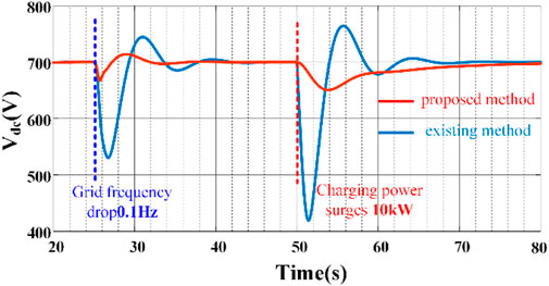
Figure 9. The transient DC bus voltage.
Figure 10 shows the experimental results of transient DC capacitor voltage. In Figure 10, Channel 1 is the DC capacitor voltage waveform. Before using the proposed method, the DC capacitor voltage dip is 51 V in Figure 10A. After using the proposed method, the dc voltage dip is basically suppressed in Figure 10B.
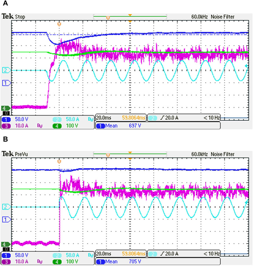
Figure 10. Experimental results. (A) the existing method. (B) the proposed method.
In Figure 11, the output power of the VSG on the grid side shows that there is an initial spike in the inertia support power before the use of the proposed method, but it is then offset by the DC voltage outer loop command and eventually goes to zero. Thus, the existing control fails to provide the inertia support power to the grid, also, there is a severe 260 V dip of dc bus voltage. By comparison, with the proposed method, the VSG instantly track the inertia support power and keep the power in the subsequent frequency regulation.
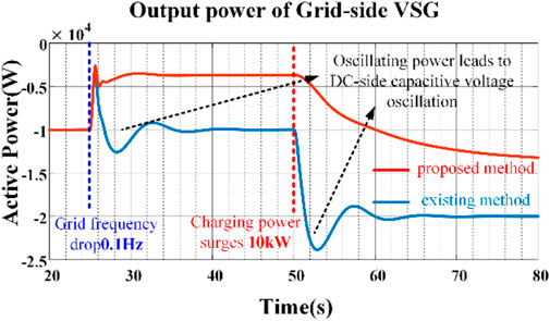
Figure 11. Transient output power of VSG.
Figure 12 shows that the DC/DC side power remains constant in the initial transient and subsequent phase using the existing method, resulting in a power imbalance with the grid side. By comparison, with the proposed method, the power on the DC/DC side dynamically follows the power on the VSG side in the transient inertia support and the subsequent frequency regulation.
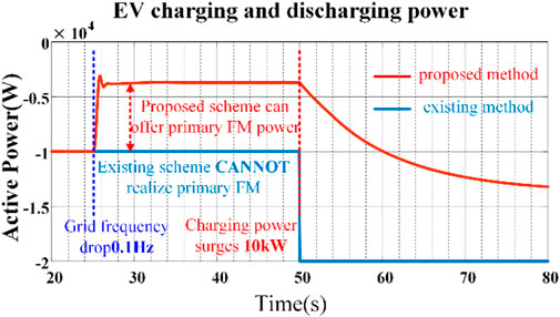
Figure 12. EV charging power.
Figure 13 shows the experimental results of the output power of the VSG on the grid side. It is seen that without the proposed technique, an initial surge in inertia support power occurs, which gets eliminated by the DC voltage outer loop command, ultimately reaching zero. Consequently, the existing control mechanism falls short of supplying inertia support power to the grid, resulting in a significant peak, about 6 kW in output power of the VSG. However, the final output power of the VSG is still zero. With the proposed method, the VSG promptly adapts to the inertia support power requirements and maintains stable at 5 kW during subsequent frequency adjustments. The experimental results are consistent with simulation results in Figure 11.
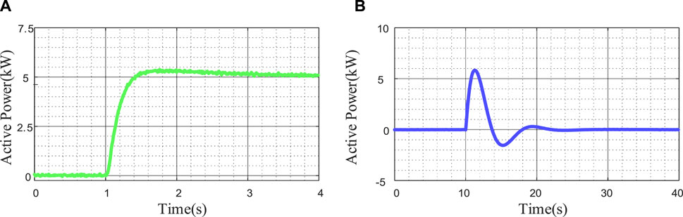
Figure 13. Experimental results when grid frequency drop (A) the proposed method. (B) the existing method.
5 Conclusion
The analysis of existing VSG based bidirectional EV charger control structure in this paper reveals its inherent limitations when realizing grid inertia support and frequency regulation. To address the problem, a new control infrastructure for VSG based bi-directional EV charging facilities is proposed in this paper. Herein, the VSG internal PD and Pout signals are used as the feedforward branches to the DC/DC power command. Additionally, the proposed control architecture includes a new command controller to get the final command to DC/DC from the PD and Pout feedforward signals. Thereby, the inertia support transient power balance is maintained within the cascaded power converters. As a result, the significant dip in the dc bus voltage is avoided, which indicates that the power on the DC/DC side is also synchronized with the frequency regulation power on the VSG side. Both the simulation and experiment results are provided to validate the effectiveness and superiority of the proposed method compared to the existing method.
Data availability statement
The original contributions presented in the study are included in the article/supplementary material, further inquiries can be directed to the corresponding author.
Author contributions
YT: Funding acquisition, Project administration, Software, Validation, Writing–original draft. BH: Validation, Writing–original draft. JF: Conceptualization, Methodology, Validation, Writing–review and editing. WC: Methodology, Supervision, Writing–review and editing. YX: Resources, Visualization, Writing–review and editing. HL: Formal Analysis, Investigation, Validation, Writing–review and editing. XL: Conceptualization, Funding acquisition, Software, Validation, Writing–review and editing.
Funding
The author(s) declare that no financial support was received for the research, authorship, and/or publication of this article.
Conflict of interest
Authors YT, BH, JF, WC, YX, HL, and XL were employed by Guangdong Power Grid Co., Ltd.
Publisher’s note
All claims expressed in this article are solely those of the authors and do not necessarily represent those of their affiliated organizations, or those of the publisher, the editors and the reviewers. Any product that may be evaluated in this article, or claim that may be made by its manufacturer, is not guaranteed or endorsed by the publisher.
References
Cui, Q., Bai, X., Zhu, S., and Huang, B. (2016). “Cost-benefit calculation and analysis of V2G system,” in 2016 China International Conference on Electricity Distribution (CICED), Xi'an, China, 10-13 Aug 2016 (IEEE), 11–62.
Fang, J., Li, H., Tang, Y., and Blaabjerg, F. (2019). On the inertia of future more-electronics power systems. IEEE J. Emerg. Sel. Top. Power Electron. 7 (4), 2130–2146. doi:10.1109/jestpe.2018.2877766
Fujita, T., Shigenobu, R., Ito, M., Kanao, N., and Sugimoto, H. (2022). Electric power system stabilization by virtual inertia and fast grid frequency support of grid-following virtual synchronous generator. Int. J. Electr. Electron. Eng. & Telecommun. 11 (4), 277–283. doi:10.18178/ijeetc.11.4.277-283
Ganne, A., and Sahu, L. K. (2024). “Performance of single-stage and dual-stage EV battery chargers for G2V and V2G operation,” in 2024 Third International Conference on Power, Control and Computing Technologies (ICPC2T) Science, Engineering and Humanities and Social Sciences references, Raipur, India, 18-20 Jan 2024.
Jiang, W., Lv, Z., Zhong, Q., Zeng, B., and Li, G. (2014a) “Virtual synchronous motor based control scheme of electric vehicle charger,” in 2014 international conference on power system technology. Chengdu, China, 2686–2692. doi:10.1109/POWERCON.2014.6993671
Jiang, W., Lv, Z., Zhong, Q., Zeng, B., and Li, G. (2014b). “Virtual synchronous motor based control scheme of electric vehicle charger,” in 2014 International Conference on Power System Technology, 2686–2692.
Jongudomkarn, J. (2021). Multivariable model predictive control for a virtual synchronous generation-based current source inverter. Int. J. Electr. Electron. Eng. & Telecommun. 10 (3), 196–202. doi:10.18178/ijeetc.10.3.196-202
Kim, H., Park, J., Kim, S., Hakim, R. M., Belkamel, H., and Choi, S. (2022). A single-stage electrolytic capacitor-less EV charger with single- and three-phase compatibility. IEEE Trans. Power Electron. 37, 6780–6791. doi:10.1109/tpel.2021.3127010
Liu, J., Miura, Y., and Ise, T. (2016). Comparison of dynamic characteristics between virtual synchronous generator and droop control in inverter-based distributed generators. IEEE Trans. Power Electron. 31 (5), 3600–3611. doi:10.1109/tpel.2015.2465852
Macioszek, E. (2019a) “E-mobility infrastructure in the Górnośląsko-Zagłębiowska Metropolis, Poland, and potential for development,” in Proceedings of the 5th world congress on new technologies (NewTech’19). Lisbon, Portugal: Avestia Publishing.
Macioszek, E. (2019b) “Analysis of trends in development of electromobility in Poland: current problems and issues,” in TranSopot conference. Cham: Springer International Publishing.
Macioszek, E. (2021) “The role of incentive programs in promoting the purchase of electric cars—review of good practices and promoting methods from the world,” in Research methods in modern urban transportation systems and networks, 41–58.
Pan, D., Wang, X., Liu, F., and Shi, R. (2020). Transient stability of voltage-source converters with grid-forming control: a de-sign-oriented study. IEEE J. Emerg. Sel. Top. Power Electron. 8 (2), 1019–1033. doi:10.1109/jestpe.2019.2946310
Shan, Z., Zhipeng, L., Ming, W., Zhenhao, S., and Ting, Z. (2019). The application of virtual synchronous generator technology in electric vehicle charger. Gongyongdian 36 (4), 24–30.
Shuai, Z., Sun, Y., Shen, Z. J., Tian, W., Tu, C., Li, Y., et al. (2016). Microgrid stability: classification and a review. Renew. Sustain. Energy Rev. 58, 167–179. doi:10.1016/j.rser.2015.12.201
Sierpiński, G., and Macioszek, E. (2020) “Equalising the levels of electromobility implementation in cities,” in Research and the future of telematics: 20th international conference on transport systems telematics, TST 2020, kraków, Poland, october 27-30, 2020, selected papers 20. Springer International Publishing.
Sun, P., Xu, H., Yao, J., Chi, Y., Huang, S., and Cao, J. (2023). Dynamic interaction analysis and damping control strategy of hybrid system with grid-forming and grid-following control modes. IEEE Trans. Energy Convers. 38, 1639–1649. doi:10.1109/tec.2023.3249965
Wang, R., Liu, H., Li, M.-J., Sun, Q., Li, X., and Wang, P. (2023). “Fast charging control method for electric vehicle-to-vehicle energy interaction devices,” in IEEE transactions on transportation electrification 9, 4941–4950. doi:10.1109/TTE.2022.3184393
Yang, X., and Hu, S. (2022). “Intelligent charging and discharging system based on V2G,” in 2022 14th International Conference on Computational Intelligence and Communication Networks (CICN), Al-Khobar Saudi Arabia, 2022 Dec 04-06 (IEEE), 702–705.
Zhang, L., Liu, Y., Hao, L., Zheng, X., Liu, X., and Li, J. (2022). “Multi-objective optimal scheduling strategy of microgrid based on V2G technology,” in 2022 12th International Conference on Power and Energy Systems (ICPES), Guangzhou, China, 2022 Dec 23-25.
Zhang, W., Cantarellas, A. M., Rocabert, J., Luna, A., and Rodriguez, P. (2016). Synchronous power controller with flexible droop characteristics for renewable power generation systems. IEEE Trans. Sustain. Energy 7 (4), 1572–1582. doi:10.1109/tste.2016.2565059
Zhong, Q.-C. (2017). Power-electronics-enabled autonomous power systems: architecture and technical routes. IEEE Trans. Ind. Electron. 64 (7), 5907–5918. doi:10.1109/tie.2017.2677339
Zhong, Q.-C., and Weiss, G. (2011). Synchronverters: inverters that mimic synchronous generators. IEEE Trans. Ind. Electron. 58 (4), 1259–1267. doi:10.1109/tie.2010.2048839
Zhou, K., Chen, S. M., Jin, N. Z., and Sun, D. Y. Research on single-phase and three-phase compatible isolated on-board charger and control technology[J]. Energies, 2022a, 15(17): 6445, doi:10.3390/en15176445
Zhou, K., Chen, S.-M., Jin, N.-Z., and Sun, D.-Y. (2022b). Research on single-phase and three-phase compatible isolated on-board charger and control technology. Energies 15 (17), 6445. doi:10.3390/en15176445
Keywords: Bi-directional EV charger, virtual synchronous generator, grid-side inertia support, cascaded power converters, power control
Citation: Tian Y, Huang B, Fang J, Chen W, Xin Y, Lin H and Lin X (2024) A new grid side inertia support control method for cascaded power converters in Bi-directional EV chargers. Front. Energy Res. 12:1396969. doi: 10.3389/fenrg.2024.1396969
Received: 06 March 2024; Accepted: 08 August 2024;
Published: 11 October 2024.
Edited by:
Fateh Krim, University Ferhat Abbas of Setif, AlgeriaReviewed by:
Amit Kumar, Thapar Institute of Engineering and Technology, IndiaElżbieta Macioszek, Silesian University of Technology, Poland
Copyright © 2024 Tian, Huang, Fang, Chen, Xin, Lin and Lin. This is an open-access article distributed under the terms of the Creative Commons Attribution License (CC BY). The use, distribution or reproduction in other forums is permitted, provided the original author(s) and the copyright owner(s) are credited and that the original publication in this journal is cited, in accordance with accepted academic practice. No use, distribution or reproduction is permitted which does not comply with these terms.
*Correspondence: Yan Tian, NDk4ODc3Mzc2QHFxLmNvbQ==