 Peihuan Li
 Zhaowei Liu1,2
- 1China National Oil and Gas Exploration and Development Company Ltd. (CNODC), Beijing, China
- 2PetroChina International Iraq FZE Iraq Branch (Halfaya), Amarah, Iraq
- 3CNOOC Research Institute Ltd, Beijing, China
More and more attention has been paid to the waterflood development of carbonate reservoir in the Middle East with continuous expansion of the scale of carbonate reservoir development. Strong non-homogeneity of carbonate reservoirs results in serious conflicts between injection and production, causing low degree of water-driven control in the well network, and low degree of vertical mobilization. This article takes the main reservoir of an oil field in the Middle East region as an example, combining geological evaluation, dynamic analysis, and reservoir development strategies to study the effectiveness of water injection development in carbonate reservoirs. It shows that there is a correlation between pore type, oil-water relative permeability, and development method in the development of carbonate reservoirs. For reservoirs with matrix pores and micropores, water injection should be strengthened in the later stage of development; for reservoirs with dissolved pores and coarse pores, the iso-permeability point is relatively high, and the later development should focus on balanced water injection. Three different waterflooding models for formation development are designed to verify the feasibility of fine waterflooding schemes. The main differences are that one set of well patterns is combined injection and production, and three sets of well patterns are layered system waterflooding. The results show that the development effect in layered system waterflooding is the best. The daily production can be increased by about 16%, the cumulative oil production can be increased by about 8%, and the recovery factor can be increased by about 3%. Eventually, the stable oil and water control of carbonate reservoir can be realized.
1 Introduction
The Middle East is rich in oil resources, and the oil and gas reserves of carbonate rock reservoirs account for more than 70% of the total reserves (Yilin et al., 2020), and the produced zone is mainly shallow-water carbonates and clastics that range in age from Infracambrian to Oligo-Miocene (Alsharhan, 2014). Moreover, the main reservoir is thick, stable in lateral distribution, good in continuity, with medium-low porosity and permeability characteristics, it is mainly deposited in shoals, continental shelves and lagoon environments at the edge of carbonate platforms. Generally, natural energy development is mainly used in the early stage of oilfield development, but as the formation pressure drops, the productivity of a single well decreases. In order to gradually restore the formation pressure, it should be gradually converted to water injection development (Song and Yong, 2018). However, carbonate reservoirs have complex pore structures, strong heterogeneity, well-developed interlayers. Different pore-throat structures show different productivity characteristics; and it is necessary to carry out detailed research on carbonate reservoirs to improve the recovery rate of main reservoirs and provide reference for further development of oilfields (Longxin et al., 2020; Feng et al., 2022a; Feng et al., 2022b).
At present, the general injection and production of extremely thick reservoirs caused serious interference between the main reservoirs in Mishrif, large differences in layered development, poor reservoir production degree and low production degree (about 40%). The recovery degree, cumulative oil production, oil production rate and other major development indicators of each layer differ greatly, and the pressure drop of water drive production<30% is unbalanced. The interlayer pressure difference is large, and the pressure attenuation of MB1 is significantly higher than that of MB2. Up to now, high permeability reservoirs (class I) and relatively high-quality reservoirs (class II) have been mainly developed, while class III and class IV reservoirs, accounting for 40%, are weakly developed or basically not developed.
At present, water injection in carbonate reservoirs still needs a lot of research in theory and practice. Song Xinmin et al. (Song and Yong, 2018) proposed that the main carbonate reservoirs in the Middle East should be replenished with water injection in a timely manner, large injection-production well spacing should be adopted, and on the basis of layered system development, flexible well types are used for development according to reservoir types, so as to achieve the maximum recovery degree extending the low water cut period. Sun Liang et al. (Liang et al., 2022) used the bi-plot method to analyze carbonate reservoir samples in the Middle East, revealed the relationship between reservoir parameters, and further clarified the types of carbonate reservoirs in the Middle East. What’s more, in view of the contradictions of general water injection development, strategies for sub-dividing interlayer systems were formulated. Shehadeh K (Masalmeh, 2002) studied the influence of wetting phase in the development of carbonate reservoirs in the Middle East and proposed that the phase permeability of water-wet rocks in this area is more curved. Based on the characteristics of carbonate rock injection and production units, Wang et al. (2020) analyzed the interference characteristics and influencing factors during the water injection process, through physical simulation experiments, the results show that injection-production well spacing, permeability ratio, etc., have great impacts on water injection in carbonate reservoirs. Yong et al. (2021) studied the periodic water injection technology of carbonate rock horizontal wells and proposed the characteristics of the reverse seven-point method and the five-point method of water injection, summarizing that periodic alternating water injection has a wider application range, higher sweep efficiency, and thereby improves reservoir recovery. Songqi (2024) proposed the water flooding performance in carbonate reservoirs, which is named “Smooth spread in high permeability layers and coning type breakthrough in low-permeability layers”. Chen et al. (2020) analyzed the effective throat radius of each rock type from the spatial distribution of pore structure, and characterized the spatial distribution of rock types through comparison with logging curves, and revealed the intrinsic connection between pore structure and sudden water injection breakthrough. The effect of water drive development in Middle East is largely influenced by reservoir geological characteristics and development technology policies. With the deepening of the water injection development process, the water flooding problems are becoming more and more obvious, such as the rapid increase of water content, the decline of oil production, and the unclear distribution of residual oil, etc (Qian, 2004; Mandefro et al., 2006b; Shudong et al., 2014; Yingzhe et al., 2022).There are significant differences in the main development indicators such as layered recovery degree, cumulative oil production, and oil recovery rate, therefore, it is necessary to conduct fine water injection research. (Lihua 2024; Xing-Wan, 2008; Mandefro et al., 2006a; Mandefro et al., 2006b; Yingzhe et al., 2022).
In this paper, taking an oil field in the Middle East as an example, combined with pore structure, seepage characteristics and actual development strategy, the high-efficiency water injection development mode of carbonate reservoir is studied, and the refined water injection development scenario is designed, so as to ultimately achieve the purpose of improving reservoir water drive sweep efficiency and recovery factor.
2 Reservoir geological characteristics
2.1 Geological characteristics
The oil field is structurally located in the Mesopotamia Basin (Chen, 2019) as shown in Figure 1. Affected by tectonic stress, it manifests as a long-axis anticline trending from NW-SE to NWW-SEE (Aqrawi et al., 2010). The anticline structural form is complete, and the stratigraphic dip angles on both wings of the main part are 2–3°. The oil field consists of Quaternary, Tertiary and Cretaceous strata from top to bottom, with a total of 9 sets of oil-bearing strata.
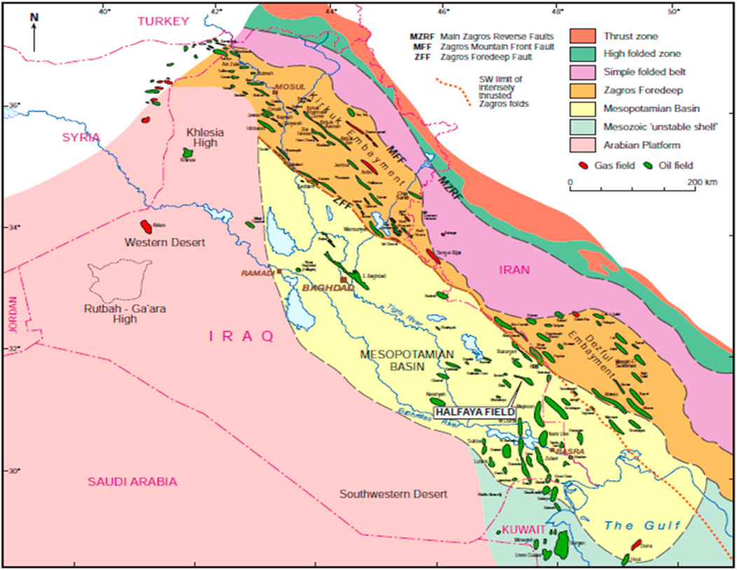
Figure 1. Structure map of Iraq.
The lithology of oilfield reservoirs is divided into two categories. The first category is carbonate rock. The mineral composition of the main reservoir rock is mainly calcite (more than 90%), followed by dolomite, quartz, etc. Its reservoir distribution has good continuity and features medium-low porosity to medium-low permeability. It mainly deposits shoals, continental shelves and lagoon environments on the edge of carbonate platform. Mainly molded/dissolved pores and micro pores, the reservoir is mainly pore type, with a small amount of dissolved pores and caves, and no micro-fractures (Lyu et al., 2021). The other type of reservoir is mainly sandstone, and the rock minerals are mainly quartz (more than 50%), followed by dolomite, clay minerals, etc. The reservoir is interbedded with fine-to medium-grained sandstone and mudstone, with multiple sand bodies being discontinuous or locally discontinuous on the plane. It has the characteristics of medium porosity and medium permeability, and is mainly deposited in tidal flat and tide-controlled delta depositional environments (Al-Dabbas and Al-Jumaily, 2010).
The Mishrif reservoir is the main production layer in the oilfield, accounting for 55% of the oilfield’s OOIP (original oil in place) (Limin et al., 2024), and it is a limestone reservoir, with formation thickness varies from 390 m to 420 m. The Mishrif formation consists of shallow open-marine, organic detrital limestones, with beds of algal, rudist, coral-reef and lagoonal facies. The reservoirs are characterized by high porosities and high permeability, such unique reservoir characteristics, which also have wide geographic extent, result in the Mishrif ranking as the number one reservoir in Iraq. So far the total proven reserves in the Mishrif reservoir exceeds 30% of the total Iraqi national reserves (Mahdi et al., 2013).
2.2 Sedimentation characteristics
As the main oil producing layers of the Mishrif reservoir, the sedimentary facies of MB1 and MB2 are shown in Figure 2. As a whole for MB1, the regularity of the distribution of the southeast northwest trending intraplatform beach and the Northeast southwest trending tidal channel are different. Scattered beach bodies are developed under the lagoon background, and tidal channels are developed at the sequence boundary, with the sedimentary characteristics of longitudinal thin interbedding and lateral rapid change. As for MB2 sedimentary characteristics, From the platform edge to the open platform, controlled by the rise and fall of sea level, the sedimentary evolution cycle of open platform beach wing bioclastic beach swamp tidal delta incised valley is developed.

Figure 2. Sedimentation map of MB1 and MB2.
2.3 Porosity and permeability characteristics
Porosity and permeability are the most basic characteristics that reflect the physical properties of oil reservoirs. The Mishrif formation in the oilfield is characterized by later age, shallow depth and weak to medium alteration of rock fabric by diagenesis, which have resulted in the medium-high porosity and medium-low permeability (Feng et al., 2018; Liu et al., 2018; Feng et al., 2021). As shown in Figure 3 and Figure 4, the main reservoir Mishrif in the area has a porosity of 13%–25% and a permeability of 2-70mD. In order to develop the main reservoir more efficiently, in view of its characteristics of medium thickness and existence of interlayers (Song and Yong, 2018), it is subdivided into 4 sets of reservoirs. Taking the main reservoir development as an example, this article mainly studies the MB1-2, MB2, and MC reservoirs.
(1) MA2 reservoir
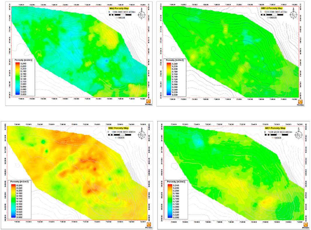
Figure 3. The porosity map.
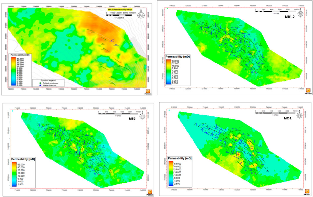
Figure 4. The permeability map.
MA1 located in the Mishrif layer is the regional sequence boundary, and MA2 is the oil-bearing reservoir. Its distribution is relatively continuous, with a reservoir thickness of 6–11 m, a porosity of 13%–16%, and a permeability of 0.5-3mD.
(2) MB1-2 reservoir
This layer is the main producing layer of the oil field, and the MB1 layer above it is the caprock, with marl and micrite limestone developed. The total thickness of the MB1-2 layer is approximately 75–90 m, the porosity is 13%–25%, and the permeability is 1-20mD.
(3) MB2 reservoir
This layer is also the main reservoir of the oil field. It is mainly deposited in a shoal facies environment, with caves developed in local areas. This layer is continuously distributed, with a thickness of 40–50 m, a porosity of 20%–25%, and a permeability of 4-70mD.
(4) MC1-1/1-2
The thickness of this layer is 40–45 m, the porosity is 15%–25%, and the permeability is 2-15mD.
2.4 Fluid characteristics
The density of crude oil in the main reservoir of the oil field is 19–25°API, the volume coefficient of crude oil under reservoir conditions is 1.3–1.5, and the viscosity of underground crude oil is 0.5-5cp. The original dissolved gas-oil ratio is 500-800scf/stb, the formation water type is CaCl2 type, the overall salinity is about 150,000–220000 ppm, and the formation water density is about 1.15 g/cm3.
2.5 Microscopic characteristics of physical properties
As we can see from Figure 5, The pore throat structure presents single peak, double peak and multi peak shapes, and the pore throat radius and capillary pressure median of different rock types show certain differences, and The rock types in different facies zones are diverse, and the rock types in the same facies zone are diverse with great differences in permeability.
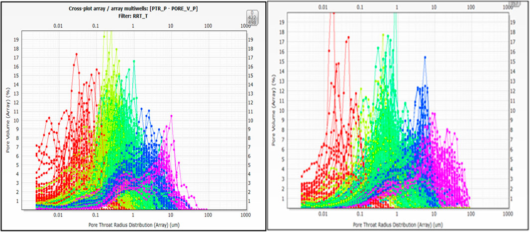
Figure 5. Pore throat radius distribution map in MB1 and MB2.
3 Characteristics of oil and water in main reservoirs of oil fields
3.1 Percolation in carbonate reservoirs
Generally speaking, the accumulation process of carbonate oil reservoirs is complex, resulting in significant differences in matrix, fracture development characteristics, physical properties, heterogeneity, fluid distribution patterns, and development performance compared to conventional oil and gas reservoirs (Zhang et al., 2018; Yichang et al., 2023; Zhang et al., 2023). Meanwhile, different pore throat structures and development methods result in different productivity distributions (Zhang et al., 2017), therefore, studying its percolation is of particular significance to guide on-site development of carbonate oil fields. The microstructure of carbonate reservoirs is complex, with primary pores, secondary pores, microfractures, and pores all serving as reservoir spaces. The variety of microstructure and connectivity methods make the microscopic flow in carbonate reservoirs more variable than that in sandstone reservoirs.
In the percolation of carbonate reservoirs in the area, matrix pores, micropore pores, and fracture pores coexist, and the reservoir medium exhibits strong heterogeneity. Due to the differences in fluid flow space and time, fluid flow in matrix pores and micropores generally conforms to Darcy’s law, while fluid flow in fracture pores generally follows the laws of fluid mechanics. During the early elastic development of oil fields, fractures serve as the main percolation pathways, which funnel crude oil into the wellbore under the influence of reservoir energy. However, during the water injection development stage, water is injected into the reservoir to replenish energy, and fractures serve only as oil-water flow pathways, with matrix pores and micropore pores serving as the main percolation spaces (Nailing, 2024).
In the process of oilfield development, the relative permeability curve is generally used to comprehensively reflect the characteristics of oil-water two-phase flow, and is widely used in field practice to study reservoir pore structure changes, oil-water saturation distribution characteristics, residual oil distribution, and water flooding efficiency. It is a powerful guiding tool in oilfield development (Jishun and Aifen, 2003; Zhao-Hong et al., 2006; Yong and Jienian, 2008; Bigno et al., 2024).
At present, the development technology dominated by carbonate rocks in the area is still based on water injection development, and It is generally believed that the oil displacement efficiency is the highest during the water-free oil production period during water flooding of carbonate reservoirs (Hongxin et al., 2022). Although the development of micro-fractures in the carbonate rock, the main reservoir in the study block is weak, field development practice shows that there are still problems such as rapid water content rise in some wells and low water injection efficiency during the actual water injection process. Therefore, conducting relative permeability research on the main reservoirs in the study block and studying the water content rise pattern can lay the foundation for efficient future development of the oil field.
3.2 Relative permeability curve of main reservoir in the oilfield
In carbonate reservoirs, as the proportion of micropores increases, the water saturation at the isotope point of the phase permeability curve shifts to the right, mainly because in the water-wet oil reservoir, water serves as a wetting phase and is mainly distributed in tiny pores, channels or in the form of water film on the surface of rock particles. Therefore, more water exists in a state of bound water. This distribution does not affect the flow of oil, causing the oil-water co-penetration interval to increase (Nailing, 2024).
In the research process, the characteristics of oil-water relative permeability in Mishrif reservoir are classified and studied. According to the characteristics of oil-water dynamic seepage, the relationship between them and static reservoir characteristics is studied. The relative permeability of Mishrif, the main reservoir of the oilfield, can be divided into three types, taking the related reservoirs of MB1, MB2 and MC as three types A, B and C respectively, and making the relative permeability curve as shown in Figure 6.

Figure 6. Reservoir relative permeability curve for MB1(Left), MB2(Middle) and MC(Right).
Combined with the oil-water permeability curves in above Figure 1 The MB1 reservoir type is dominated by matrix pores and microspores, the water phase permeability at the residual oil end is less than 0.4, and the oil-water phase permeability and iso-permeability point are low; (2) The MB2 reservoir type is dominated by dissolved pores and coarse pores, and the reservoir permeability is relatively high. The relative permeability curve of the oil phase decreases rapidly, the oil-water co-permeability range is wide, and the oil-water phase permeability iso-permeability point is relatively high. (3) The MC reservoir type is dominated by micro-fracture pores, and the oil phase permeability drops rapidly in the early stage. As water saturation increases, its rate of decline gradually slows down, while the relative permeability of the water phase accelerates as water saturation increases (Zhanguo, 2011; Ning, 2015; Haibo et al., 2019). This type of curve has the lowest iso-permeability point during the oil-water seepage process.
It can be seen from the phase permeability curve that the curves have different shapes at different layers of the reservoir in the study area. Overall, as the water saturation increases, the water phase rises faster from MB1 to MC, and the residual oil saturation is relatively high. Therefore, during the oilfield development process, reservoir water injection should be optimized based on the seepage characteristics of different layers to improve oilfield recovery and ultimately achieve water control and oil increase.
3.3 Water drive efficiency of main reservoir in oilfield
After analyzing the physical parameters of carbonate reservoir, it can be seen that sequence, sedimentation, diagenesis and tectonism jointly control the formation and evolution of the reservoir. The heterogeneity of thick carbonate reservoir is strong, the micro pore system is complex, and the thief formation aggravates the uncertainty in the early stage of waterflood development.
During the actual oilfield development process, the water flooding oil production efficiency and distribution frequency of each layer of the main reservoir were compared, as shown in Figure 7.
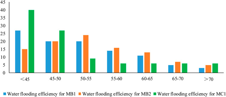
Figure 7. Frequency comparison diagram of water drive efficiency distribution of each reservoir.
It can be seen from the figure that the average water drive efficiency of the MB1 layer is about 45%, and the main distribution range of water drive efficiency is <55%, accounting for about 70%; The average water drive efficiency of the MB2 layer is about 51%, and the main distribution range of water drive efficiency is 45%–65%; The average water drive efficiency of MC1 layer is about 40%, and the main distribution range of water drive efficiency is <50%. It can be seen from the water drive efficiency distribution frequency diagram that the MB2 reservoir has better physical properties and higher water drive efficiency, MC2 has the lowest water flooding efficiency. Compared with other strata, the MC1 reservoir is more heterogeneous and its microscopic pore structure is more complex. It has both microspores, fracture pores and hole pores, causing poor performance of water drive efficiency at the micro level.
4 Research on fine water injection in main reservoir of oilfield
4.1 Research background
From the oil-water phase permeability curve, it can be seen that in the oil-water percolation of the main reservoir in the area, the permeability of its water phase rises faster, which is easy to cause low water-drive efficiency or water flooding, which seriously affects the development of the oilfield; at the same time, according to the water-drive efficiency diagram of the layer system, the MB2 layer has the highest water-drive efficiency, and the next step of the development of the field is mainly for the balanced injection of water into this layer system, so as to realize the stabilization of the layer system and control of the water, and the water-drive efficiency of the MB1 and MC2 layers is to be further improved. For MB1 and MC2, the water-driven efficiency should be further improved, and the next development strategy is to strengthen the water injection and improve the water-driven ripple coefficient.
At present, in the process of oilfield development, the main indicators such as the recovery degree, pressure maintenance level and injection production ratio between MB1 and MB2 differ greatly. The edge and bottom water invasion of the main reservoir Mishrif is intensified, and the water cut rises rapidly, affecting the stable production in the future. In terms of pressure, there is currently a significant difference in pressure between the Mishrif layers. The average pressure drop in the MB1 layer is 1800psi, and the average pressure drop in the MB2 layer is 1000psi. As it can be seen from Figure 8 that water cut for both MB1 and MB2 rises rapidly, and additionally, due to the rapid pressure decay in the MB1 layer and the development of high permeability zones, there is a risk of water breakthrough and low water drive efficiency.
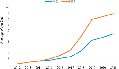
Figure 8. Average water cut in MB1 and MB2.
Compared with conventional oil reservoirs, the oil reservoir type in the area belongs to medium-thick to extremely thick carbonate oil reservoirs, with oil layer thickness greater than 70 m, the vertical thickness difference is large, the reservoir physical property difference is large, and the heterogeneity is strong. There are significant differences in the facies types, reservoir sizes, and physical properties of the Mishrif series, as well as differences in the degree of utilization, pressure attenuation, and water content characteristics (Liu et al., 2019; Mahdi and Aqrawi, 2014). The contradictions between the generalized development layers are prominent, the vertical utilization of the Mishrif series is currently uneven, with only 30%–50% utilization in the multi-layer joint production profile, and many reserves have not been utilized, seriously affecting the oilfield recovery rate.
Meanwhile, according to the layer water flooding efficiency map, the MB2 layer has the highest water flooding efficiency. In the next step of oilfield development, the main focus is to balance water injection into this layer system to achieve stable oil and water control in the layer system. For the MB1 and MC2 layers, their water drive efficiency needs to be further improved. The next development strategy is mainly to strengthen water injection and improve the water drive sweep coefficient.
4.2 Background of fine water injection
In response to trends such as rising water content in oilfield development, we should comprehensively consider reservoir properties, interlayers, connectivity relationships and production dynamics to study and implement refined water injection, thereby improving the water flooding efficiency of carbonate reservoirs and achieving stable oil and water control (Liang et al., 2019).
(1) Sedimentary environment
As shown in Figure 9, the carbonate reservoir MB1 of the well group in the experimental area is mainly composed of granular and muddy limestone in a limited platform environment. It is weakly eroded by atmospheric fresh water and has strong cementation, resulting in a smaller pore throat.
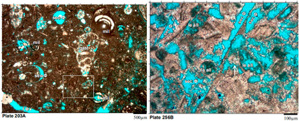
Figure 9. Reservoir structure for MB1(Left) and MB2(Right).
As shown in Figure 9 MB2 is mainly composed of granular limestone and muddy limestone in the platform edge environment. It is strongly corroded by atmospheric fresh water, has relatively large pore throats, and has medium to high permeability physical properties.
(2) Interlayer
As shown in Figure 10, it can be seen from the logging map that there is a developed interlayer between MB1 and MB2 in the carbonate rocks of the well group in the experimental area, the bottom of MB1 is mainly composed of low-energy granular limestone with poor physical properties and wide development, which can block the flow of fluids up and down. At the same time, MDT testing showed a significant pressure breakpoint between MB1-2 and MB2, indicating the development of interlayer between MB1 and MB2, as well as differences in upper and lower pressure attenuation, degree of utilization, and energy supplementation.
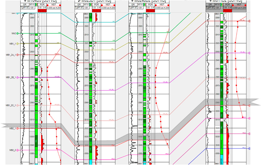
Figure 10. Logging response diagram.
As it can be seen from Figure 11, MB1 is dominated by lagoon facies grainstone and MB2 is mainly composed of swamp facies carbonaceous mudstone and lagoon facies grainstone.
(3) Permeability difference
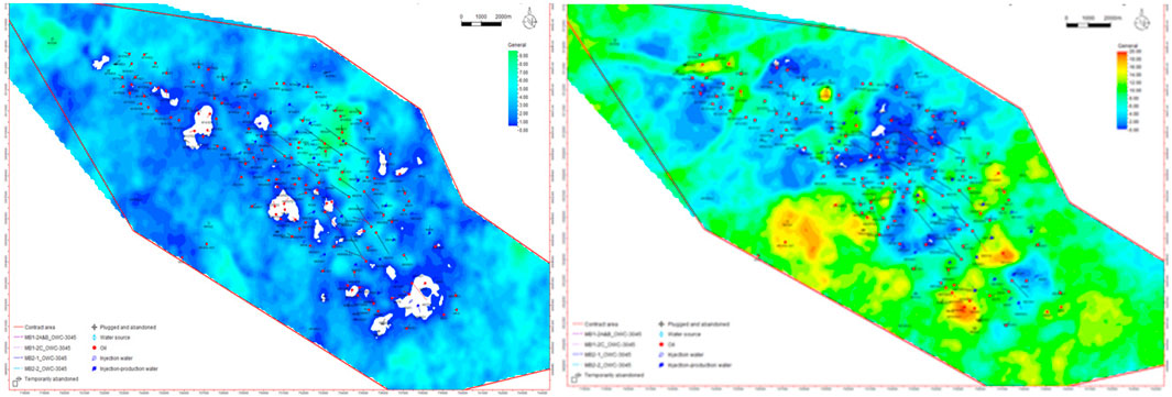
Figure 11. MB1 Baffle thickness map for MB1(Left) and MB2(Right).
As can be seen from Figure 12, the permeability of MB1 layer is between 25 and 40md, and that of MB2 layer is between 70 and 90md. The difference in permeability between layers is obvious.
(4) Well pattern perfection
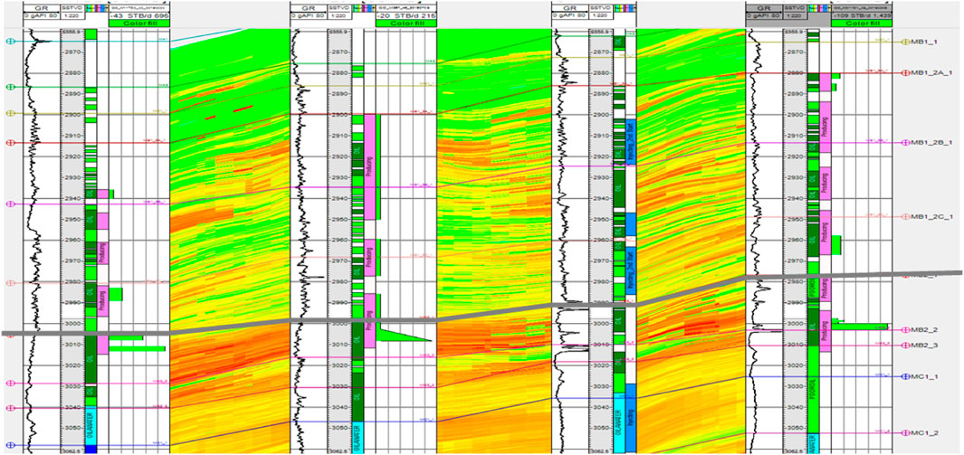
Figure 12. Permeability profile.
As shown in Figure 13, the well groups MB1 and MB2 in the experimental area have not formed a perfect injection production well pattern, and the proportion for injection wells and production wells is low, the relationship between oilfield injection and production is imperfect, and the degree of reserve utilization is uneven vertically. The contribution of MB1 production is 20%–30%, and that of MB2 production is 70%–80%. At the same time, due to the uneven recovery degree, the interlayer pressure between MB1 and MB2 is quite different.
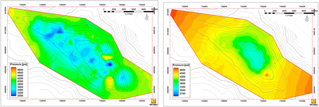
Figure 13. MB1 Formation pressure for MB1(Left) and MB2(Right).
In terms of interlayer, permeability and pressure, MB1, MB2 and MC have good geological conditions for layered system development. Layered water injection development is conducive to improving the injection production relationship, improving water drive efficiency, and achieving oil stability and water control.
4.3 Fine water injection scenario design
To achieve reservoir balance and efficient utilization, based on reservoir characteristics and development and production dynamics, three different layer series development water injection modes are designed to verify the feasibility of comparing and refining water injection scenario. The main adjustment goal is to establish a complete injection production well network, improve the utilization of MB1, reduce the water content of MB2, achieve overall balanced utilization of Mishrif reservoir, improve water drive efficiency, and maintain long-term stable production.
As shown in Figure 14, Figure 15, Figure 16, Scenario A is a set of well network layer system development, the injection and recovery method is combined injection and recovery, and the water injection method adopts area injection; Scenario B adopts two sets of well network layer system development, the upper MB1 adopts area injection, and the lower MB2 adopts edge injection; Scenario C is a fine water injection scenario, and it adopts three sets of well network layer system development, and the upper MB1 improves the utilization of the reservoir section, and it adopts area injection; the lower MB2 has better physical properties, stable oil layer zoning and high flow coefficient, and adopts edge water injection to extend the reservoir waterless oil recovery period; MC2 layer system makes full use of the blocking effect formed by the local compartmentalized interlayer, ensures the water avoidance height, and controls the water content, so it adopts the bottom water injection method and utilizes the horizontal wells to recover the oil.

Figure 14. Scenario A- one set of well pattern.
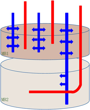
Figure 15. Scenario B two sets of well pattern.
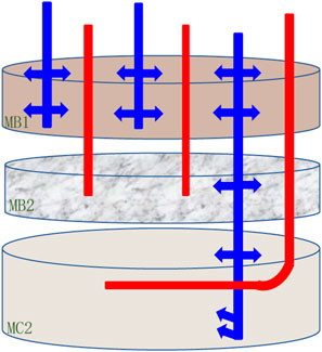
Figure 16. Scenario C—three set of well pattern.
4.4 Development effect comparison
The development effects of the three scenario are compared and analyzed from the aspects of production and water cut. The development effect of layered system is obviously better than that of general water injection. After the fine water injection scenario of scenario C is adopted, a relatively perfect injection production correspondence is formed in MB1 interval, and the dynamic effect is significantly improved in MB2 interval.
(1) Development effect of MB1 strata
It can be seen from Figure 17 and Figure 18 that after 20 years of cumulative development, the water content of scenario B and scenario C is about 70%, and the water content of scenario C rises more slowly; scenario C improves the reserve production of MB1, has high water drive sweep efficiency and production degree, increases the cumulative oil production, and the vertical production degree is more balanced.
(2) Development effect of MB2 strata
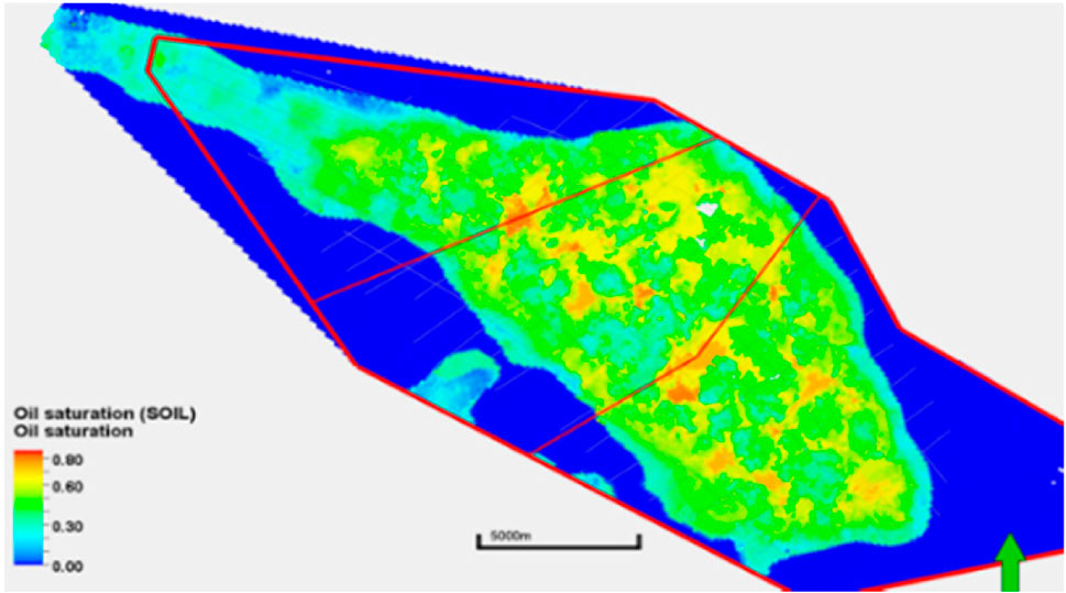
Figure 17. The water drive sweep of scenario B after 20 years of development for MB1.
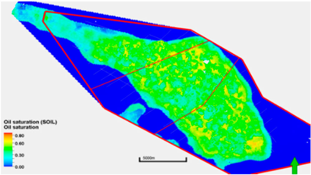
Figure 18. The water drive sweep of scenario C after 20 years of development for MB1.
It can be seen from Figure 19 and Figure 20 that scenario B and scenario C can maintain stable production for a long time, and the water cut is greatly reduced. After 20 years of cumulative development, the water drive sweep in scenario C is higher than that in scenario B, and the cumulative oil production is significantly higher than that in scenario B.
(3) Reservoir vertical development effect

Figure 19. The water drive sweep of scenario B after 20 years of development for MB2.
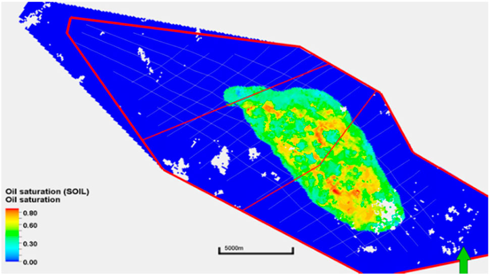
Figure 20. The water drive sweep of scenario C after 20 years of development for MB2.
From Figure 21 and Figure 22, it can be seen that the longitudinal water-driven wave in each layer of scenario C is significantly better than that of scenario B. The adjustment strategy of water injection and development in the layered system effectively solves the water-driven utilization difference and development imbalance between MB1 and MB2, and realizes the balanced utilization of the reservoir as a whole.

Figure 21. Longitudinal water drive sweep of scenario B after 20 years of development.

Figure 22. Longitudinal water drive sweep of scenario C after 20 years of development.
Based on the water injection study for the development of the Mishrif sublayer system in the main reservoir, the overall indexes were compared, as shown in Table 1, compared with the generalized water injection development of scenario A, the development of the three layer systems in scenario C can increase the daily production by 16%, reduce the daily injection and cumulative water production by about 30%, increase the cumulative oil production by 8%, and increase the recovery rate by about 3%.
(4) Saturation Comparison
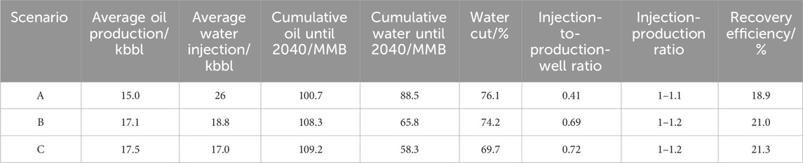
Table 1. Comparison of development scenario.
As it can bee seen from Figure 23, as for scenario A, one set of well pattern is seriously flooded and the oil-water relationship is more complex; and as for scenario C, the fine water injection system using edge water injection and bottom water injection can better control the water cut, and the displacement is more uniform, which can improve the oil recovery.
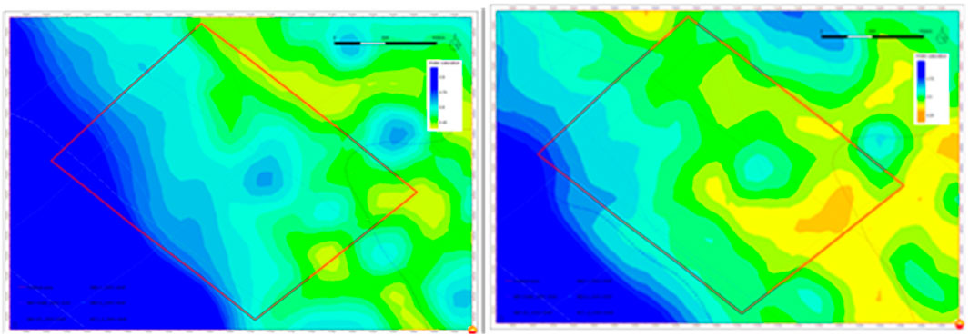
Figure 23. Oil saturation in scenario A(Left) and scenario C(Right).
The comparison of cumulative oil production and cumulative water production development of the three scenario is shown in Figure 24, from which it can be seen that the development of layered system can significantly improve the degree of reserve utilization, improve the efficiency of water drive wave, improve the degree of vertical utilization, slow down the rate of rise of the water content in carbonate reservoirs, and prolong the time of stable production of the oil field.
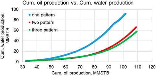
Figure 24. Fig of cumulative oil production - cumulative water production comparison.
5 Conclusion
1. The pore structure of carbonate reservoirs in the Middle East is complex and heterogeneous, In matrix pores and micropores, the fluid flow basically conforms to Darcy’s law, In the fracture pores, it basically follows the law of fluid mechanics. The fine water injection research on carbonate reservoir can effectively control the rise of water cut in the oilfield, improve the injection production relationship, and improve the water drive efficiency, and achieve oil stability and water control eventually.
2. In carbonate reservoirs, there is a correlation between pore types, oil-water relative permeability, and development methods. Reservoirs dominated by matrix pores and micropores have lower iso-permeability points and lower water drive efficiency. Therefore, later development should focus on strengthening water injection. Oil reservoirs with mainly dissolved and coarse pores have relatively high iso-permeability points and a wide oil-water co-permeability zone, resulting in high water drive efficiency. However, the water content increases rapidly, and later development should focus on balanced water injection.
3. Considering the reservoir properties and types in the study area, implementing three sets of layer series development and refined water injection research can achieve maximum oil recovery. Improve the reservoir profile utilization of the MB1 strata by using area injection water; the MB2 strata has good physical properties, stable oil reservoir zoning, and high flow coefficient. Therefore, edge water injection is adopted to prolong the anhydrous oil recovery of the reservoir; The MC2 layer system should fully utilize the barrier effect formed by local interlayers to ensure water avoidance height and control water content. Therefore, bottom water injection method is adopted.
Through layered development and refined water injection, daily production can be increased by about 16%, cumulative oil production can be increased by about 8%, and oil recovery can be increased by about 3%. At the same time, daily injection and cumulative water production can be reduced by about 30%, which effectively improves the degree of reserve utilization.
Author contributions
PL: Writing–original draft, Writing–review and editing. ZL: Writing–review and editing. LC: Writing–review and editing. YC: Writing–review and editing.
Funding
The author(s) declare that no financial support was received for the research, authorship, and/or publication of this article.
Conflict of interest
Authors PL, ZL, LC were employed by China National Oil and Gas Exploration and Development Company Ltd. (CNODC) and PetroChina International Iraq FZE Iraq Branch (Halfaya).
Author YC was employed by CNOOC Research Institute Ltd.
Publisher’s note
All claims expressed in this article are solely those of the authors and do not necessarily represent those of their affiliated organizations, or those of the publisher, the editors and the reviewers. Any product that may be evaluated in this article, or claim that may be made by its manufacturer, is not guaranteed or endorsed by the publisher.
References
Al-Dabbas, M., and Al-Jumaily, A. J. (2010). Depositional environments and porosity distribution in regressive limestone reservoirs of the Mishrif Formation, Southern Iraq. Arabian J. Geosciences. doi:10.1007/s12517-009-0057-x
Alsharhan, A. S. (2014). Petroleum systems in the Middle East. Geol. Soc. Lond. Spec. Publ. 392 (1), 361–408. doi:10.1144/sp392.19
Bigno, Y., Al-Bahry, A., Melanson, D. D., et al. (2024) Multilateral waterflood development of a low-permeability carbonate reservoir.
Chen, M., Cheng, L., Lu, T., et al. (2020). Pore structure characterization and its impact on waterflooding development in Khasib reservoir in Ahdeb Oilfield, Iraq. Lithol. Reserv. 32 (03), 133–143. doi:10.12108/yxyqc.20200313
Chen, P. (2019). Characteristics of micro-fractures in carbonate reservoir of Mishrif formation, B oilfied of Iraq. J. Northeast Petroleum Univ. 43 (6), 62–72. doi:10.3969/j.issn.2095-4107.2019.06.007
Feng, D., Bakhshian, S., Wu, K., Song, Z., Ren, B., Li, J., et al. (2021). Wettability effects on phase behavior and interfacial tension in shale nanopores. Fuel 290, 119983. doi:10.1016/j.fuel.2020.119983
Feng, D., Chen, Z., Wu, K., Li, J., Dong, X., Peng, Y., et al. (2022a). A comprehensive review on the flow behaviour in shale gas reservoirs: multi-scale, multi-phase, and multi-physics. Can. J. Chem. Eng. 100 (11), 3084–3122. doi:10.1002/cjce.24439
Feng, D., Chen, Z., Wu, K., Li, J., Gao, Y., Bi, J., et al. (2022b). Dynamic behavior of miscible binary fluid mixtures in nanopores: implications for CO2-enhanced oil flow in shale reservoirs. Fuel 327, 125128. doi:10.1016/j.fuel.2022.125128
Feng, D., Li, X., Wang, X., Li, J., and Zhang, X. (2018). Capillary filling under nanoconfinement: the relationship between effective viscosity and water-wall interactions. Int. J. Heat Mass Transf. 118, 900–910. doi:10.1016/j.ijheatmasstransfer.2017.11.049
Haibo, S., Wang, X., Zhang, S., et al. (2019). Fractal characterization method for oil-water relative permeability model in low-permeability reservoirs. J. Northeast Petroleum Univ. 43 (05). doi:10.3969/j.issn.2095-4107.2019.05.009
Hongxin, G. U. O., Cheng, L., Peng, WANG, et al. (2022). Water flooding experiment and law of carbonate reservoir cores with different fracture occurrences. Petroleum Geol. Recovery Effic. 29 (6), 8. doi:10.13673/j.cnki.cn37-1359/te.202111038
Jun, Y. A. O., Xin, W., Wang, C., et al. (2013). The influence of carbonate rocks reservoir parameters on microscopic flow. Earth Science-Journal China Univ. Geoscience (5), 6.
Liang, S. U. N., Yong, L. I., and Baozhu, L. I. (2022). Classified evaluation methods and waterflood development strategies for carbonate reservoirs in the Middle East. Acta Pet. Sin. 43 (2), 270–280. doi:10.7623/syxb202202009
Liang, W. E. I., Jiang, W., and Su, H. (2019). Main influencing factors of waterflooding efficiency and injection technique policy of carbonate reservoir in Middle East. Petrochem. Ind. Technol. 26 (05), 170–171.
Lihua, S. H. I. (2024) Study on water injection development mechanism and fine water injection control in ultra-low permeability reservoir. Beijing: China University of Petroleum.
Limin, Z., Duan, T., Han, H., et al. (2024) Case study of fine geological modeling for Mishrif carbonate reservoir of H oilfield in Iraq[C]//Spe/iatmi asia pacific oil & gas conference & exhibition.
Liu, H., Tian, Z., Liu, B., Guo, R., Yang, D., Deng, Y., et al. (2018). Pore types, origins and control on reservoir heterogeneity of carbonate rocks in Middle Cretaceous Mishrif Formation of the West Qurna oilfield, Iraq. J. Petroleum Sci. Eng. 171, 1338–1349. doi:10.1016/j.petrol.2018.08.034
Liu, J., Gao, J., Bo, L., et al. (2019). Mainly geological control factors and distribution of the upper cretaceous Mishrif carbonate reservoir, R oilfield in the Middle East. Bull. Sci. Technol. 35 (05), 13–20+29.
Longxin, M. U., Chen, Y., et al. (2020). Technological progress and development directions of PetroChina overseas oil and gas field production. Petroleum Explor. And Dev. 47 (01), 120–128.
Lyu, M., Song, B., Changbing, TIAN, et al. (2021). Key controlling factors of permeability in porous carbonate reservoirs of Mishrif Formation in the Middle East. Petroleum Geol. Recovery Effic. 28 (3), 7. doi:10.13673/j.cnki.cn37-1359/te.2021.03.008
Mahdi, T. A., and Aqrawi, A. A. M. (2014). Sequence stratigraphic analysis of the mid-cretaceous Mishrif formation, southern mesopotamian basin, Iraq. J. Petroleum Geol. 37 (3), 287–312. doi:10.1111/jpg.12584
Mahdi, T. A., Aqrawi, A. A. M., Horbury, A. D., et al. (2013) Sedimentological characterization of the mid-Cretaceous Mishrif reservoir in southern Mesopotamian Basin. Iraq: Geoarabia –Manama.
Mandefro, B., Geiger, S., Matthai, S. K., et al. (2006a). Numerical simulation of water injection into layered fractured carbonate reservoir analogs. Aapg Bull. 90, 1473–1493. doi:10.1306/05090605153
Mandefro, B., Geiger, S., Matthai, S. K., et al. (2006b). Numerical simulation of water injection into layered fractured carbonate reservoir analogs. Bull. Int. Union Against Tuberc. 85 (10), 363–365.
Masalmeh, S. K. (2002). The effect of wettability on saturation functions and impact on carbonate reservoirs in the Middle East. Abu Dhabi Int. Petroleum Exhib. Conf. doi:10.2118/78515-MS
Nailing, X. I. U. (2024) Research of flow mechanism of fissure-cavern carbonate reservoirs. Institute of Porous Flow and Fluid Mechanics of Chinese Academy of Sciences.
Ning, L. I. (2015) Experimental study of oil-water phase infiltration curves in fractured reservoirs. Southwest Petroleum University.
Qian, X. (2004). Status of hydrocarbon development in the oil-producing countries of the Middle East (IV). Arab. World (06), 30–33.
Shudong, CHEN, Junhe, X. I. N., et al. (2014). China Petroleum overseas drilling engineering technology status and future prospects. Oil Drill. Prod. Technol. (2), 1–5. doi:10.13639/j.odpt.2014.02.001
Songqi, L. I. (2024) Multi-scale research on microscale mechanism and macroscale performance of water flooding in carbonate reservoirs. Beijing: China University of Petroleum.
Song, X., and Yong, L. I. (2018). Optimum development options and strategies for water injection development of carbonate reservoirs in the Middle East. Petroleum Explor. And Dev. 45 (4), 11. doi:10.11698/PED.2018.04.13
Wang, J., Zhao, W., Huiqing, L. I. U., et al. (2020). Inter-well interferences and their influencing factors during water flooding in fractured-vuggy carbonate reservoirs. Petroleum Explor. And Dev. 2020 (005), 047. doi:10.1016/S1876-3804(20)60117-3
Xing-Wan, T. (2008). Successful practice for carbonate reservoir development by cyclic water injection process. Xinjiang Pet. Geol. 29 (6), 735–736.
Yichang, Y. U., Rui, G. U. O., Minjie, L. I. N., et al. (2023). Pore throat structure characteristics and development countermeasures of carbonate reservoirs in the Middle East: a case study of M formation in the X oilfield in Iraq. Acta Pet. Sin. 44 (02), 369–384. doi:10.7623/syxb202302012
Yilin, W., Song, X., Wang, G., et al. (2020). Key technologies and practices for rapid and large-scale production increase in cooperation oil and gas fields of the Middle East. Acta Pet. Sin. 41 (12), 1633–1642. doi:10.7623/syxb202012015
Yingzhe, M., Guofeng, W., and Yuan, F. (2022). Application of multi-stage hydraulic fracturing of horizontal well in Halfaya Oilfield, Iraq. China Pet. Explor. 27 (5), 138. doi:10.3969/j.issn.1672-7703.2022.05.013
Yong, L. I., Zhao, L., Wang, S., et al. (2021). Using cyclic alternating water injection to enhance oil recovery for carbonate reservoirs developed by linear horizontal well pattern. Petroleum Explor. And Dev. 48 (05), 986–994. doi:10.1016/S1876-3804(21)60097-6
Yong, S., and Jienian, Y. Characterization and prevention of formation damage for fractured carbonate reservoir formations with low permeability.2008, 5(4):8.
Zhang, L., Chengyong, L. I., Zhao, Y., et al. (2017). Review on the seepage mechanisms of oil and gas flow in fractured carbonate reservoirs. Earth Sci. 42 (08), 1273–1286. doi:10.3799/dqkx.2017.101
Zhang, T., Sun, T., et al. (2023). Pore-scale simulation of gas-water two phase flow in carbonate reservoir with different combinations of pore, network and hole. J. southwest petroleum Univ. Technol. Ed. 45 (05), 88–96. doi:10.11885/j.issn.1674-5086.2021.11.26.03
Zhang, T., Xiangfang, L. I., Xiangzeng, WANG, Hu, K., Sun, F., and Han, S. (2018). Gas water relative permeability model for tight sandstone gas reservoirs. Sci. Sin. Technol. 48 (10), 1132–1140. doi:10.1360/n092017-00148
Zhanguo, L. U. (2011) Fluid flow law in fractured vuggy media. China University of Petroleum Doctoral Dissertation.
Keywords: middle east, carbonate reservoir, reservoir percolation, efficient water injection, mishrif reservor
Citation: Li P, Liu Z, Cai L and Chen Y (2024) The research on high efficiency water injection development of carbonate rock reservoir in the middle east. Front. Energy Res. 12:1396480. doi: 10.3389/fenrg.2024.1396480
Received: 05 March 2024; Accepted: 29 March 2024;
Published: 16 May 2024.
Edited by:
Yan Peng, China University of Petroleum, Beijing, ChinaReviewed by:
Yanwei Wang, China University of Geosciences, ChinaWei Zhang, SINOPEC Petroleum Exploration and Production Research Institute, China
Copyright © 2024 Li, Liu, Cai and Chen. This is an open-access article distributed under the terms of the Creative Commons Attribution License (CC BY). The use, distribution or reproduction in other forums is permitted, provided the original author(s) and the copyright owner(s) are credited and that the original publication in this journal is cited, in accordance with accepted academic practice. No use, distribution or reproduction is permitted which does not comply with these terms.
*Correspondence: Peihuan Li, Y3VwbHBodWFuQDEyNi5jb20=