 Boikhutso Mosepele
 Ravi Samikannu
 Lilian Amuhaya
- Department of Electrical and Communications Systems Engineering, Botswana International University of Science and Technology, Palapye, Botswana
Classical multilevel inverter (MLI) topologies have gained widespread interest in industry and academia because of the improved qualities they offer over their two-level counterparts. MLIs are characterized by reduced Total Harmonic Distortion (THD) and high power conversion efficiency. Classical MLI topologies, however, are not without drawbacks; generally, they require many components as the number of output waveform levels is increased, resulting in high cost and complex implementation. Furthermore, MLIs based on flying capacitors have issues with capacitor voltage balancing and high inrush currents. As a result, this has prompted researchers to develop reduced component count (RCC) or reduced switch count (RSC) and hybrid topologies to achieve high power quality, but at reduced cost and complexity in comparison to classical MLI topologies. This article evaluates the merits and demerits of recently proposed reduced switch count and hybrid topologies, identifies challenges and opportunities, and proposes further research and development for the improvement of multilevel inverters. This review paper will be helpful to those conducting research in the field of MLI technology.
1 Introduction
Society is more than ever compelled to efficiently utilize existing energy resources while also incorporating Renewable Energy Sources (RES) into the energy infrastructure. This move is aimed to reduce Greenhouse Gases (GHG) emissions, comb the imminent climate crisis, and meet the increasing demand for electricity around the world. This energy demand has promoted the development of alternative sources such as wind turbines, tidal energy generation, Photovoltaic (PV), and green hydrogen energy systems (Ashok Kumar et al., 2021). PV systems are becoming cost-competitive against conventional thermal power generation systems and will be a major source of electrical power in the future (Ullah et al., 2020).
Power inverters are a crucial component of photovoltaic systems. They are responsible for increasing the input voltage and converting the DC power to AC power that can be connected to the grid or used in standalone systems. Typically, inverters have multiple stages of conversion, where the first stage is a DC-DC converter that increases the input voltage and performs Maximum Power Point Tracking (MPPT). The final stage of the inverter chain is the DC-AC converter. In some cases, the photovoltaic system may require transformers for galvanic isolation.
Power quality is a crucial aspect of power inverters. Ideally, inverters should produce a pure sinusoidal waveform, but this is not always possible in real-life applications (Cherkaoui Jaouad et al., 2022). To achieve high power output power quality, 2-level inverters must be switched at high frequencies, resulting in decreased conversion efficiencies (Kabalcı, 2021). However, the introduction of multilevel inverters has led to cost reduction, lower Total Harmonic Distortion (THD), and improved efficiency (Vakacharla et al., 2020).
Improvements on the inverters can be attributed to two factors, the development of new topologies and control methods that incorporated innovations and modernization in semiconductor and computing technologies. With MLI, high voltage inverters that were previously unfeasible with 2-level inverters due to power rating constraints on semiconductor switches can now be implemented (Kala and Arora, 2017). MLIs offer several other benefits over 2-level inverters, such as reduced rate voltage change over the change in time (dV/dt), lower common-mode voltages, and elimination of the need for bulky output filters (Rodriguez et al., 2009; Dhanamjayulu et al., 2022a; Atar et al., 2023).
Multilevel inverters offer many advantages, but they also have some drawbacks. The cost of the many switching devices and passive components necessary for MLIs can be a limiting factor in their potential applications. This article discusses the research that is being done in academia and industry to develop new reduced switch count and hybrid multilevel inverter topologies. These topologies aim to achieve high output power quality and improved efficiency with reduced switch counts and low complexity. It is important that topologies proposed as reduced switch count types do not come at the expense of increased complexity or use of multiple voltage sources. To assess the features and benefits of new advanced topologies, several key parameters are taken into consideration: total harmonic distortion, component count, efficiency, and complexity (Bhaskar et al., 2020; Sedaghati et al., 2022; Stöttner et al., 2022; Wikipedia, 2024). Figure 1 shows the classification of multilevel inverters. They may be categorized into single source, multiple source, resonant, and reduced switch count inverters. Only reduced switch count types and their improvement types or hybrids will be reviewed in this article and are highlighted in blue in the figure.
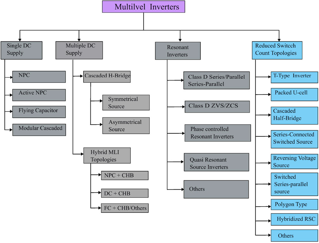
Figure 1. Classification of MLI topologies based on supply and topological structure.
Research in multilevel inverters is an ever-evolving endeavor, and newer topologies that bring better performance are always contributed to the body of knowledge. In (Mehta and Puri, 2022), a review of reduced component MLI topologies classified as symmetric, asymmetric, and hybrid configurations was presented (Bughneda et al., 2021), reviewed photovoltaic systems and highlighted promising use cases of MLI in such systems (Barros et al., 2022), looked at modular multilevel inverters, their submodules, and modulation techniques, and (Jana et al., 2017) reviews multilevel topologies with a focus on soft-switched topologies. A recent review publication (Vinay Kumar and GowriManohar, 2023), reviewed and classified RSCs in asymmetric and symmetric topological structures, and compared their performance merits. The authors observed superior characteristics in asymmetrical structures in terms of higher efficiency, better switch utilization, and low THD. This review article takes a different approach not only to review topologies and their operations, advantages, and disadvantages but also to identify research opportunities for further development.
The paper is structured as follows. Section 2 presents a topological review of classical MLIs, discusses their advantages, and disadvantages, and highlights the motivation to move towards reduced switch count and hybrid MLIs; Section 3 provides an overview of modulation techniques that can be applied to MLI, Section 4 presents an analysis of recently proposed reduced switch count inverters and hybrid multilevel inverters, Section 5 summarizes the advantages and disadvantages of the reviewed topologies, and suggests potential research opportunities for further development, and Section 6 of the paper summarizes the conclusions and observations that were made during the review process.
2 Classical multilevel topologies
The neutral-point clamped (NPC), cascaded h-bridge (CHB), and flying-capacitor (FC) MLIs were the first invented MLI topologies and are referred to as classical topologies. Coverage of the fundamental topologies is done extensively in other publications, (Abd Halim et al., 2016; Choudhury et al., 2021; Barnawi et al., 2023), and a summary is presented in this article for brevity. The CHB requires the least number of components among the three, as shown in Figure 2; Table 1, the reason for its widespread adoption in industrial applications. The main drawback of CHB MLI is the requirement for independent voltage sources, the provision of which is often achieved with expensive transformers. Asymmetric configurations of the CHB have the advantage of generating many voltage levels with fewer power sources and components, although this comes at a loss of redundancy, fault tolerance, and modularity (Rotella et al., 2006; Barzegarkhoo et al., 2016; Kannan et al., 2017; Busarello et al., 2018; Kumar Gupta and Bhatnagar, 2018; Chitra and Valluvan, 2020; Odeh et al., 2021). The resulting implementations have increased cost and complexity. FC MLIs have capacitor voltage balancing problems and high inrush currents. The NPC has the highest number of components. The issue with NPCs is the voltage balancing of the DC link capacitors at the input as the number of levels increases, which can cause undesirable transients that can damage the switching devices if not properly managed (Ahmad et al., 2024; Kieferndorf et al., 2000; Es-Saadi et al., 2018; Ghani et al., 2023). When the FC is compared to the NPC, the FC requires half the number of flying capacitors and clamping diodes compared to the NPC, resulting in a significant reduction in component count and cost. Additionally, the FC offers redundancy in configurations to generate zero output voltage, which can be valuable for optimization purposes (Chang-xin et al., 2009; Bressan et al., 2019; Humayun et al., 2020; Laamiri et al., 2017; Vincotech, 2024). In summary, all three have the benefit of generating low THD waveforms but in general, require many components to generate at high levels. A quantitative summary of component count for the three topologies is shown in Table 1 on the basis of the number of sources (NDC), number of switches (NSW), number of diodes (ND), and number of capacitors (NC). A qualitative summary is presented in Table 2, summarizing the merits and demerits of each topology. Great effort is directed toward developing multilevel inverters to enhance the level count while using fewer components.
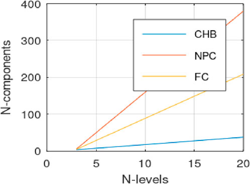
Figure 2. Number of components versus number of output levels in classical topologies.
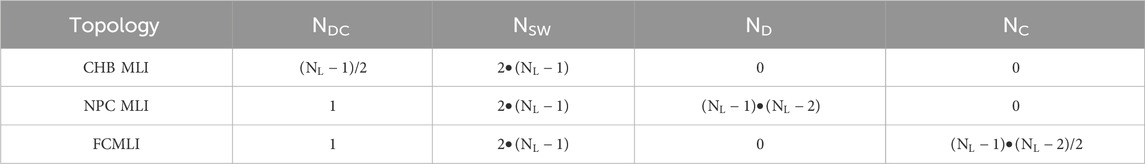
Table 1. Comparison of classical MLIs on number of DC sources and numbers of different components.
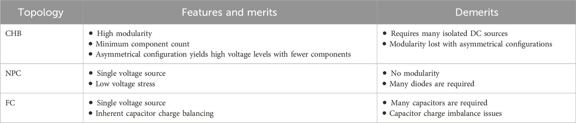
Table 2. Qualitative comparison of classical MLIs.
3 Multilevel modulation techniques
Multilevel inverters need specific switching patterns to achieve the desired output voltage. Various techniques have emerged over time to control the topologies, and modulation techniques are an advanced field on their own. These techniques can be categorized on the basis of switching frequency into high-frequency and low-frequency techniques. Although there are many modulation techniques available, here we present a summary of some of the commonly used ones found in the literature (Kumar Gupta and Bhatnagar, 2018).
3.1 High-frequency techniques
High-frequency pulse width modulation (HFPWM) techniques include space-vector pulse width modulation (SVPWM) and multi-carrier PWM. SVPWM is less popular due to its high complexity for many-level MLI. Multi-carrier methods, as the name suggests, make use of multiple carriers of triangular or sawtooth waveforms. The frequency, amplitude, phase of each carrier, and delay between carriers can be adjusted to improve performance. With all this freedom present, many multi-carrier methods have been proposed. An N-level inverter requires N-1 carrier signals. The methods include phase deposition PWM(PD-PWM): here all carrier signals are in phase and level-shifted; phase opposition disposition PWM(POD-PWM): with this technique, carrier signals above and below zero reference are shifted by 180°; phase shift PWM(PS-PWM): here all the carrier signals are shifted at some angle which determines the performance of modulation; variable frequency carrier bands PWM(VFCB-PWM): for this technique, all the carriers can assume different frequencies; carrier overlapping PWM(CO-PWM): for this modulation scheme, the carrier signals overlap each other; and alternate phase opposition disposition (APOD-PWM): in this scheme, the carrier signals are alternatingly phase shifted by 180°. The modulation method we choose has a significant impact on the inverter THD performance. In (Oghorada et al., 2019), the authors investigated the use of PS-PWM, PD-PWM, and two proposed modulation methods on a 5L-FCMLI. In (Harin et al., 2017), a simulation comparison of different modulation techniques is carried out on a 3Linverter and the results showed that PD-PWM generated waveforms with the least THD.
3.2 Low-frequency techniques
Space vector control (SVCPWM) calculates the switching times based on a space vector representation of the reference voltage together with the possible switching states (Mayorga et al., 2021). In (Lewicki et al., 2023), a new SVPWM algorithm with DC link voltage balancing capability is proposed for a three-phase 7-level CHB system. It was demonstrated to increase control of DC link voltages compared to other methods. In (Jayakumar et al., 2021), the authors review SVCPWM control technique in conventional 2-level and 3-level NPC and compare it to multiple carrier techniques presented in the previous section. SVC is demonstrated to provide better DC-link voltage balancing, common mode voltage reduction, better THD, and switching loss reduction.
The nearest-level control method, also known as staircase modulation in some publications, is an important technique for high voltage inverters. However, if it is used for low voltage level inverters, it produces low order harmonics that are difficult to filter (Kumar et al., 2022). In (Ramu et al., 2022), an evaluation of LSPWM, PSPWM, and NLC is carried out on RSCMLI. Nearest-level control demonstrated the highest efficiency due to reduced switching losses at low switching frequencies. In (Busarello et al., 2019), a clear understanding of NLC is presented for an ACHB MLI, with calculations for the power distribution between CHB cells. It is argued that asymmetric MLIs benefit greatly from NLC for their high efficiency.
3.3 Hybrid modulation techniques
Hybrid modulation combines carrier-based high-frequency modulations and fundamental-frequency modulation strategies (Tamilvani and Valluvan, 2012). For the same reason that hybrid multilevel inverters inherit good characteristics from the individual topologies, hybrid modulation seeks to marry the benefits of each. The outcome is reduced switching losses and high-power quality, two competing merits in multilevel inverters. Fundamental frequency signals generate a square wave to establish the main part of the reference signal. The square wave is then subtracted from the reference signal, creating the difference reference signal which is compared against the high-frequency carrier signal for the generation of drive signals for other switches. An additional benefit is the reduced number of required carrier signals and hence reduced computational requirement. The hybrid modulation is applied to provide high-voltage fundamental-frequency and low-voltage high-frequency switching operations resulting in reduced switching losses. In (Jiang et al., 2017), carrier-based PWM is combined with SVPWM for a 3-level NPC, resulting in increased efficiency.
4 Reduced switch count and hybrid multilevel inverter topologies
In the work of Thakre et al. (Thakre et al., 2022), the authors developed a topology as shown in Figure 3, that can accommodate symmetric and asymmetric voltage sources to improve the level count. The basic module of the topology consists of two unidirectional switches, two free-wheeling diodes, and two isolated voltage sources and can generate 3 voltage levels. Its ability to generate enhanced level count is overshadowed by the many voltage sources, which make it a cost-sensitive topology. The polarity inversion full bridge driving the output limits application to low and medium-voltage applications.
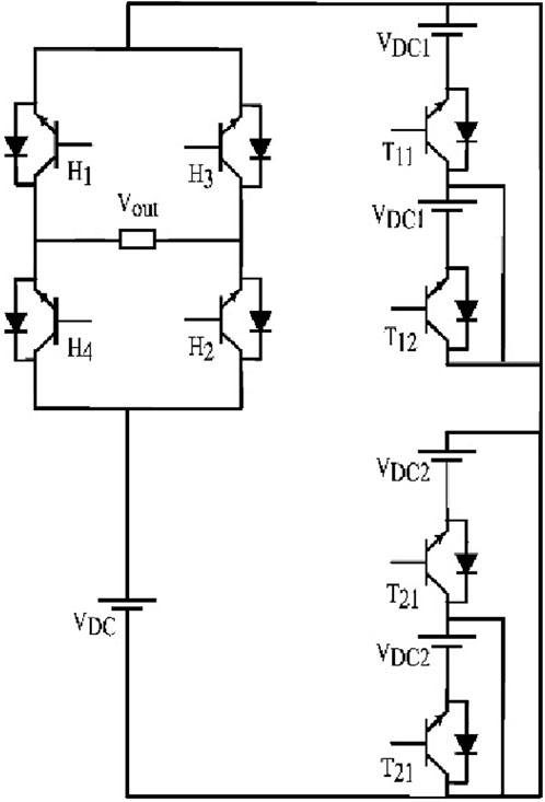
Figure 3. Proposed multilevel module-based 11-level MLI in [Thakre et al. (2022)].
Ahmed et al. (2018), proposed a reversed source half-bridge multilevel inverter, eliminating the need for a dedicated polarity generator. It is usually custom to employ a full-bridge front end for this specific purpose of polarity generation, however, the front end in this case requires switches of high voltage blocking capability vis-a-vis the level generation switches and will only be limited to low voltage applications. To eliminate the full bridge front-end, the authors developed the topology as shown in Figure 4, that inherits simple cascaded half-bridge modules. Cascaded half-bridges cannot generate negative voltages, and to solve this, the authors implemented another half-bridge module with a negative polarity voltage equal to all the other cascaded positive modules combined. Intermediate voltage levels are generated through subtractive operations. The control complexity is low, and the asymmetric nature allows for low frequency modulation to enhance efficiency. Nevertheless, the negative half bridge limits its application to low-voltage applications and the many power sources can increase the cost.
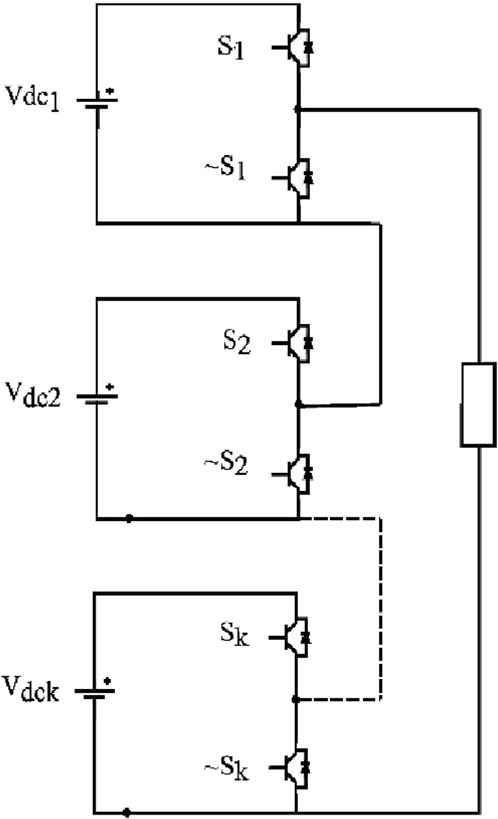
Figure 4. Cascaded half-bridge MLI (Ahmed et al., 2018).
In their paper Islam et al. (2023) proposed a five-level voltage-boosting switched capacitor MLI as shown in Figure 5. This structure consists of seven switches, 3 diodes, and 2 capacitors that act as virtual voltage sources. The topology uses a full-bridge frontend for polarity inversion, which makes it highly modular and extensible for high-voltage applications, although that comes at the expense of many voltage sources. The capacitor voltage balancing is inherent and allows for simple control. The switch utilization is low for this topology.
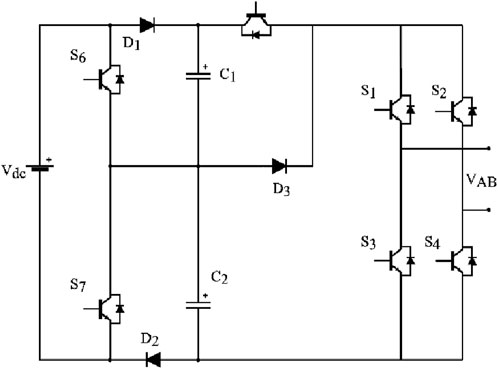
Figure 5. Switched capacitor MLI (Islam et al., 2023).
A switched series-parallel source multilevel inverter is proposed in (51) with a single DC source and 2 switched capacitors. Using capacitors in a topology to replace voltage sources helps to reduce the overall component count in a system. The inverter as shown in Figure 6, generates a 7-level output waveform and inherently balanced capacitor voltages. The excellent merit of the topology is the boosting capability, which additionally eliminates the need for boost converters, especially in renewable energy systems. The topology is highly modular and can be extended either by adding more switched capacitor units in series or cascading through the outer full bridge. The switch S2 has the highest conduction loss compared to other switches. This unbalanced nature will lead to reliability issues. Another downside of the topology is that the number of carrier signals used is tied to the voltage gain. This requires increased computational capability when extending and is costly. Fundamental-frequency modulation may erode the capacitor balancing capability and therefore not appropriate. Hybrid modulation can be explored to try to reduce the quantity of carrier signals.
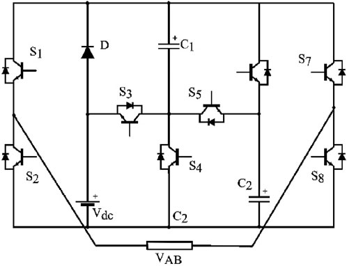
Figure 6. Series-parallel capacitor source proposed in [Jena et al. (2023)].
A 31-level topology is presented in (52) to enhance output level count and shown in Figure 7 with asymmetric input voltage sources. The level generation circuits are innovative; however, the structure requires isolated voltage sources, in this case, provided using a high-frequency link which makes it unattractive cost-wise. As with all asymmetric topologies, the level count is enhanced. Generally, the component count is reduced on the level generation side but taking into account the high-frequency link and its associated components the prices will be compounded. The topology is complex, considering all the design variables including the design and sizing of the high-frequency transformer. It makes up for the demerits with high efficiency associated with low-frequency modulated asymmetric structure.
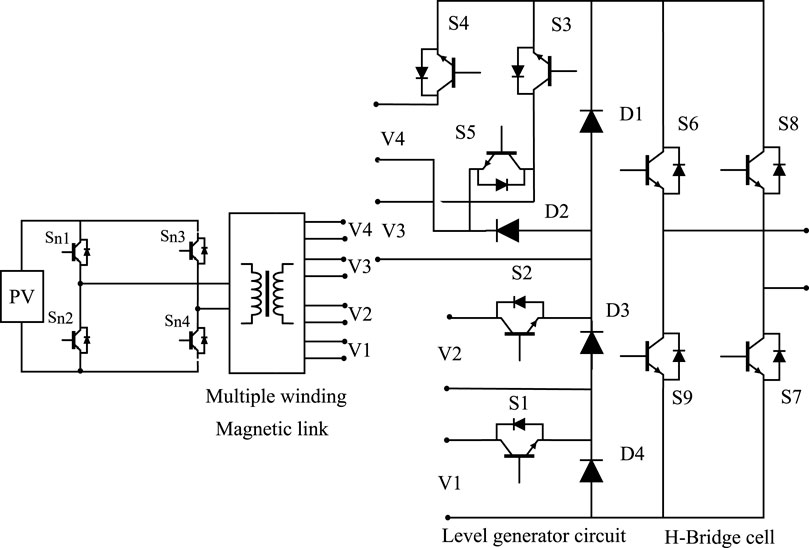
Figure 7. High-frequency magnetic-linked source-switched MLI in [Islam et al. (2020)].
In (53), the authors present a novel high-frequency linked series switched-source MLI shown in Figure 8. It distinguishes itself from the topology in (52) by using the high-frequency transformer to generate only the low-voltage sources in an asymmetric configuration. The main voltage input to the inverter is supplied directly from the voltage source, hence the lack of complete galvanic isolation. The center-tapped secondary winding output allows for an enhanced level generation with the switched rectifier circuits, however, the many rectifiers involved considerably reduce the efficiency to a reported 95%. The topology still retains many components and the output full-bridge limits it to low to medium-voltage applications. However, cascading allows the system to be built to higher voltages, albeit costly considering the transformers.
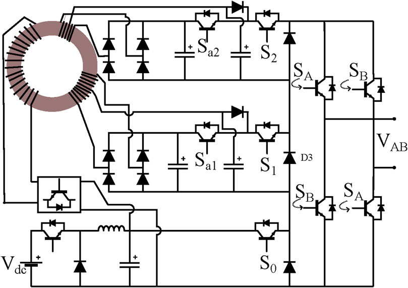
Figure 8. High-frequency link switched rectifier MLI (Hatas et al., 2023).
In (54), a novel 13-level switched capacitor MLI with a voltage gain of six is proposed and is depicted here in Figure 9. The topology combines a switched capacitor series-parallel unit and an L-type unit for extending to high levels and gain. The topology benefits from a high number of complementary switching pairs, reducing the cost of drivers. The high gain is an advantage, especially for photovoltaic applications where the requirements for a boost converter are eliminated. However, the carrier signal requirement is twice the gain, making the control complex. The topology has inherent capacitor voltage balancing, an additional feature for reducing complexity. The structure could benefit from decoupling the charging of C1 and C2 in parallel, charge them independently and benefit from enhanced voltage gain and still retain the extensibility offered by the L-type unit. Furthermore, all the capacitors are charged in series with the voltage source and the addition of a series inductor can help with limiting the initial inrush currents.
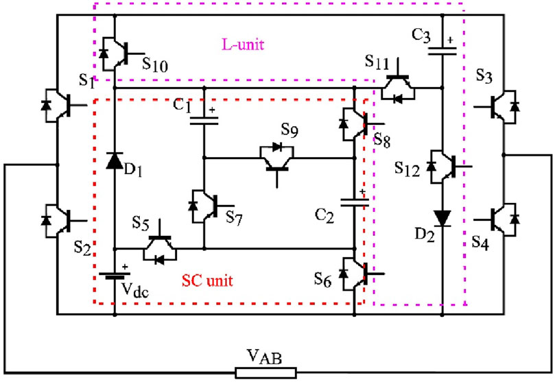
Figure 9. 13-level SC with series-parallel and L-type units (Deng et al., 2023).
In (55), a series-connected switched-source configuration with an auxiliary module and polarity changing full bridge is proposed. The topology was designed with hybrid modulation in mind from the onset and is shown in Figure 10. The switched sources are dedicated to the level generation, switched at low frequency, and the auxiliary modules, are switched at carrier signal frequency to smoothen the output waveform. The zero level is generated by the polarity changing full-bridge. All voltage sources must be equal to avoid short-circuiting through the body diodes. For this reason, it cannot accommodate asymmetric configurations. The voltage sources can be connected in parallel to share the load equally. One major benefit is that if the auxiliary module source is chosen to be half of the series sources, the number of levels generated is doubled. The topology generates a high number of levels with very few switches but requires isolated voltage sources even for the minimal configuration. Because the polarity is generated through the full bridge, it is limited to low to medium voltage applications. Even though possible to cascade, it would prove expensive. The topology benefits from a high number of complementary switches, reducing the cost of drivers drastically.
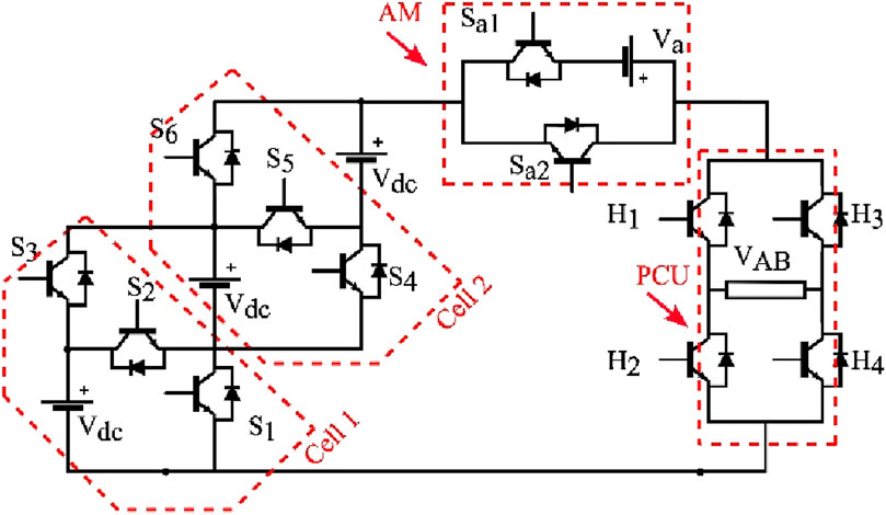
Figure 10. 9-level series-connected switched-source MLI (Bassi and Salam, 2019).
Kumari et al. (2023), proposed a 5-level extendible topology as shown in Figure 11. Its simple structure and inherent capacitor voltage balancing reduce the complexity of control. The design has retained a full bridge end, making it highly modular and extensible for higher voltage applications. For single source applications, it will only be limited to low-voltage applications. Its low gain makes it unattractive for photovoltaic applications requiring high gains. The topology has inherent voltage balancing capability. A single discharging state is always followed by two charging states, giving it a good capacitor voltage balancing capability and making it suitable for high-current applications.
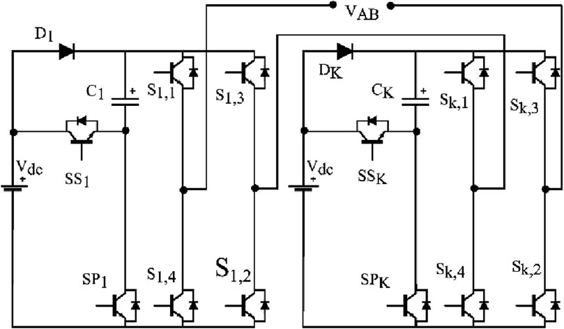
Figure 11. MLI switched capacitor with reduced switch count (Kumari et al., 2023).
In reference (Khan et al., 2022), a new topology of switched-capacitor is presented as shown in Figure 12. The topology and switching patterns implemented for it are designed to achieve inherent self-balancing of capacitor voltages, eliminating the need for auxiliary circuits and reducing the control complexity. The authors solve the issue of high inrush currents by incorporating a series inductor and implementing a precharge soft-start modulation scheme. The quasi-resonant recharging operations reduce losses considerably, a big advantage as low-loss capacitor charging or resonant charging in multilevel inverters is a current topic. With the inclusion of the pre-charge soft start, the control complexity has increased.
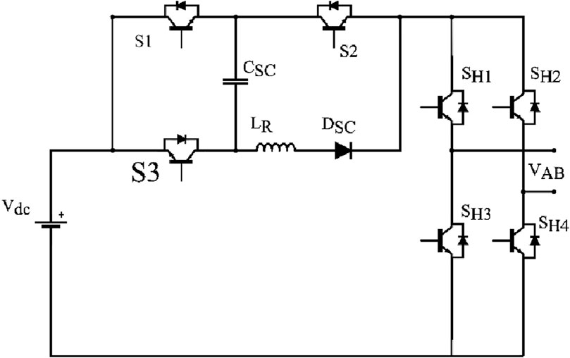
Figure 12. Single-phase 5-level SC MLI (Khan et al., 2022).
Sheik Tanzim et al. (Meraj et al., 2021), proposed a novel hybrid T-type inverter, a hybridization of a T-type, and a cross-switched MLI shown in Figure 13. The multisource structure allows for asymmetric configurations for increased level generation. The structure is extensible although the requirement for many isolated voltage sources is a drawback, and complexity is greatly increased. The cross-connected voltage sources require higher voltage blocking devices, a variation that will increase costs. Notwithstanding, the topology uses low-frequency switching, resulting in good efficiency results. The main drawback of this topology is the many different voltage sources.
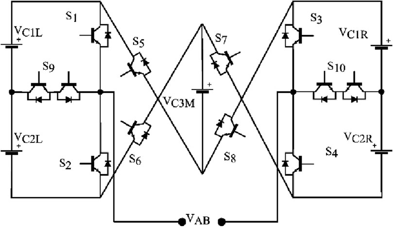
Figure 13. Hybrid T-type multilevel inverter (Meraj et al., 2021).
Dhanamjayulu et al. (2022b), have proposed a novel 35-level asymmetric inverter applicable to renewable energy and electric mobility systems, comprising of eight unidirectional switches, 2 bidirectional switches, and five voltage sources. The inverter is shown in Figure 14. All asymmetrical topologies have the advantage of producing many levels with fewer components, but this topology contains a high number of voltage sources. The topology has four bidirectional switches designated as S1, S2, S6 and S12. The topology lacks extensibility and is limited to low to medium-voltage applications. As each of the voltage sources is of a different size, power distribution, and handling is unbalanced and varied. It is suited to battery systems where isolated power sources are readily available. The reported efficiency of the inverter is 93.37%, a comparatively poor performance figure in general, owing to the many switches present.
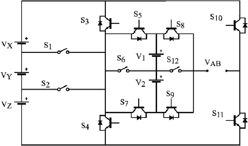
Figure 14. 35-level inverter in [Dhanamjayulu et al. (2022b)].
Figure 15 illustrates the 17-level asymmetric polygon-type asymmetric 17-level RSC MLI proposein (Samadaei et al., 2019). The topology is constructed with 2 voltage sources and 2 switched capacitors. One source has voltage Vdc while the second has 3Vdc, with the same scaling for the capacitor sources. The topology employs the NLC modulation technique that results in low switching losses. The switching states and the corresponding output voltages are presented in Table 14. The 1Vdc source is used to charge the 1Vdc capacitor, and the same is true for the 3Vdc source and capacitor. The inherent capacitor charging is achieved through careful planning of the switching paths. Both capacitors are charged one after the other within one window at the 0Vdc output voltage and their charging paths are created as follows: to charge the 1Vdc capacitor, switches S1, S2, S4, S8, and S11 are engaged; and to charge the 3Vdc capacitor, switches S4, S5, S6, S7 and S11 are switched ON. The sizing of the capacitors is such that it charges with sufficient charge to last all switching states within one-half of a single fundamental cycle. With such a long discharging period and a single short window for charging capacitors, high voltage ripples will be present. Very large and expensive capacitors will be necessary to keep voltage ripples to a minimum.
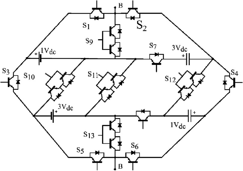
Figure 15. Polygon-type MLI proposed in [Samadaei et al. (2019)].
Srivivasan et al. proposed switch-ladder MLI (SLMLI) shown in Figure 16 (Srinivasan et al., 2021). The structure generates an output voltage of 81 levels. The output voltage levels can be increased by increasing the number of DC sources within the cell or through cascading modules or stages with fixed DC sources. The latter will use fewer switching devices compared to the former when increasing MLI voltage levels. In the presented topology. V1 = Vdc, V2=(z+2) * Vdc, V3=(4z) *V1, V4=(z+2) *V3. Negative output values are generated by the polarity inversion full bridge. The nearest-level modulation technique was employed and achieved low THD values. The topology can generate a high number of levels, however the modules use four voltage sources and cascading the modules increases the cost and complexity even further.
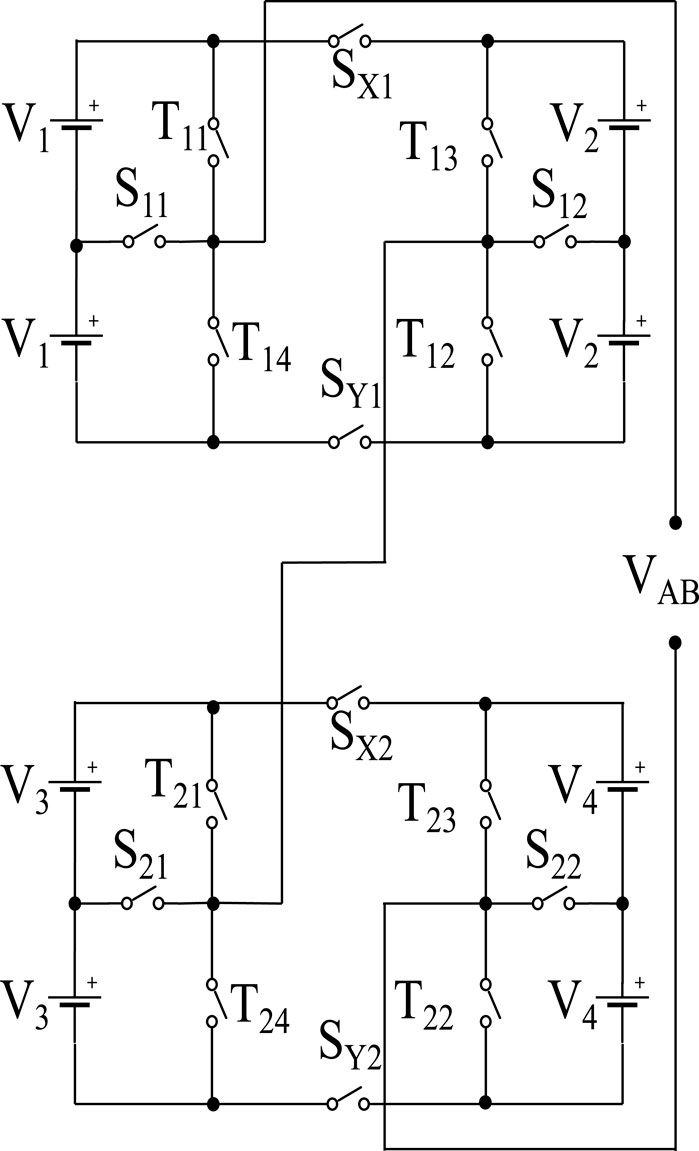
Figure 16. Switch-ladder MLI in [Srinivasan et al. (2021)].
In (62) an asymmetric H-6 topology is proposed and depicted in Figure 17. The structure uses an H-6 inverter with a string of isolated DC sources on either side of the H-6 cell. The DC sources are controlled by the outer switches for level generation and the center switches SH1-SH6 are used for polarity inversion. The level generation switches operate at high PWM frequencies while the H-bridge switches operate at fundamental frequency to reduce the switching loss. Asymmetric voltage sources can be chosen for the DC source values yielding a high number of output levels. This is a highly complex topology and requires isolated voltage sources. In practical terms, obtaining different voltage ratios with photovoltaic systems or fuel cells can make the implementation expensive. It is suitable for battery operated inverters.
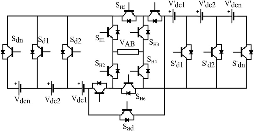
Figure 17. Hybrid H-6 MLI proposed in [Radhakrishnan et al. (2024)].
Siddique et al. proposed in (63) a new design of 11-level active neutral-point clamped (ANPC) inverter with high gain for photovoltaic applications. Figure 18 shows the inverter topology, consisting of a single voltage source, two switched capacitors, and 12 switching devices. Of the 12 switches, S1, S2, S5, S8, S9, and S10 have voltage ratings of the input DC source, S3 and S4 have half the DC source rating, switched S6, S7, S11 and S12 have voltage ratings twice the DC source voltage. The variability in the switch rating makes the inverter design complicated. Since the topology has a voltage gain of 2.5, it is well suited for use in photovoltaic systems and eliminates the need for a separate boost converter. The switch utilization, however, is low.
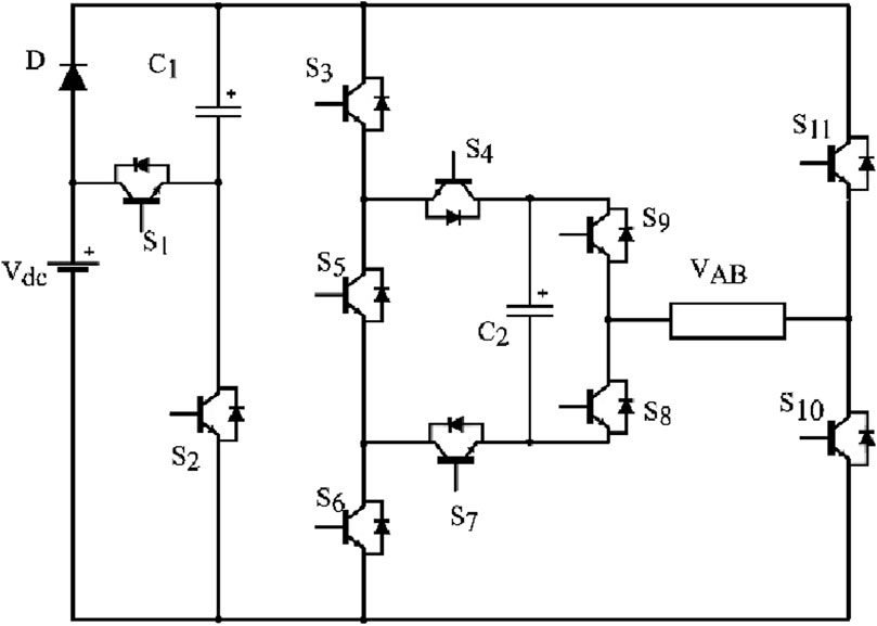
Figure 18. 9-level SC proposed in [Daula Siddique et al. (2022)].
In (64), a 9-level SC inverter with voltage boost and capacitor self-balancing capability is proposed and shown in Figure 19. It consists of two switched capacitors, C1 and C2. C1 is charged to the input voltage and C2 is charged to 2Vin, through a series connection of C1 and the input voltage source. The topology is capable of switching at fundamental frequency, leading to efficient implementation. Having a gain of four eliminates the need for boost converter for photovoltaic applications. The topology’s main drawback is that it retains many switches. It boasts inherent capacitor voltage balancing but suffers from high inrush currents at startup.
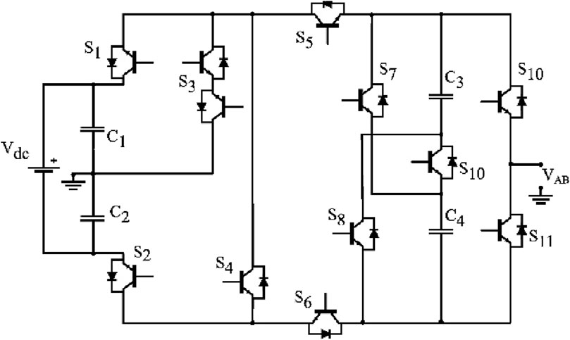
Figure 19. 11-level ANPC proposed in [Samadaei et al. (2019)].
In (65), a modified 7-level packed U-cell (PUC) inverter with voltage gain is presented and shown in Figure 20. The traditional 7-level PUC has a single voltage source Vdc and a capacitor source clamped to Vdc/3. The downside of this topology is the requirement for external closed-loop control for capacitor voltage balancing. The complexity is high. To solve the issue of voltage balancing, a PUC5 was invented along with a novel modulation method with inherent voltage balancing in (Abarzadeh et al., 2019). Both the PUC7 and the PUC5 are attractive with their low switch counts, but they lack voltage gain and as such not suitable for where voltage boosting is required as so in photovoltaic systems. The generic PUC is extensible but requires many voltage sources because the level generation is done for the most part by subtraction of voltage sources. In the modified PUC presented here, the capacitor is replaced by a voltage source with reversed polarity, and this allows the generation of higher voltage amplitude through the additive series connection of V1 and V2. In the case of modified PUC, V1 = 2V2, and the output voltages that are generated are 0, ±Vdc, ±2Vdc, ±3Vdc. The requirement for more than one voltage source is a disadvantage for this topology. An opportunity presents itself to explore a PUC7 with inherent voltage balancing and will be mentioned in the following section.
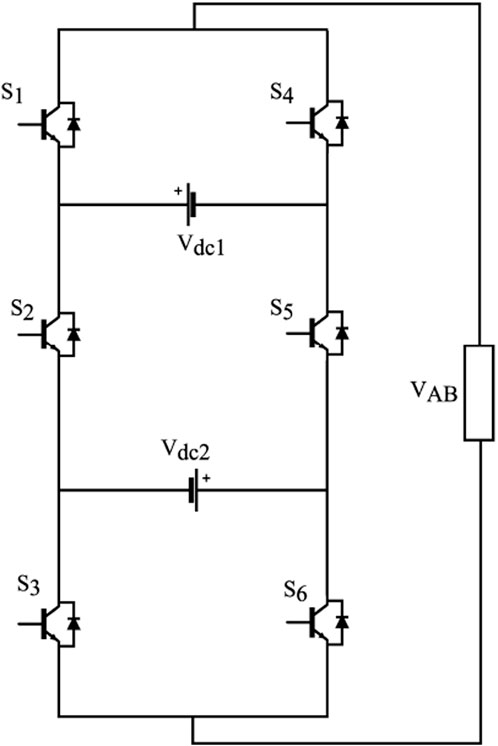
Figure 20. Modified 7-level PUC (Shojaei et al., 2019).
5 Discussion
Table 3 summarizes the features, and points out the merits, and demerits of the reviewed MLI topologies. Table 4 shows a comparative analysis of the different topologies on the basis of the number of levels generated (NL), number of switches (NSW), number of diodes (ND), number of magnetic transformers or inductors (NTR/IND), the ratio of levels to the total number of components (NL/NCOMP), and lastly a statement of the whether the reported topology employes asymmetric sources or not.It is crucial to understand that the overall cost of MLIs increase with a rise in the number of components, voltage sources and the complexity involved to implement the modulation strategies. The review looked at recently proposed inverters categorized as reduced switch count topologies. While galvanic isolation can be mandatory, the trend is in favor of nonisolated topologies as they are cost-effective. The topologies reported in (Ahmed et al., 2018; Samadaei et al., 2019; Islam et al., 2020; Meraj et al., 2021; Srinivasan et al., 2021; Dhanamjayulu et al., 2022b; Thakre et al., 2022; Hatas et al., 2023; Radhakrishnan et al., 2024) benefit from the use of asymmetric configurations to achieve high switch utilization or generate a high number of levels. This comes at the expense of a loss of modularity, which is highly desired to extend topologies for high voltage applications. The aforementioned topologies, utilizing multiple active voltage sources, present with high complexities as it is not the case that isolated voltage source are readily available. The cost of implementing multiple voltage sources is likely to be prohibitive. Single voltage source topologies utilizing capacitors to achieve voltage gain and level generation are attracting more attention from industry because or their low cost and manageable complexities. Many switched capacitor topologies are proposed, as those reviewed in this article, (Khan et al., 2022; Deng et al., 2023; Islam et al., 2023; Jena et al., 2023; Kumari et al., 2023), and increased research in this domain will lead to more optimal designs. Single source switched-capacitor topologies are favourable. In developing many-level SC topologies, soft-charging of capacitors becomes ever more important to be incorporated in inverters beyond five levels or single capacitor.

Table 3. Summarized features, merits, and demerits of reviewed topologies.
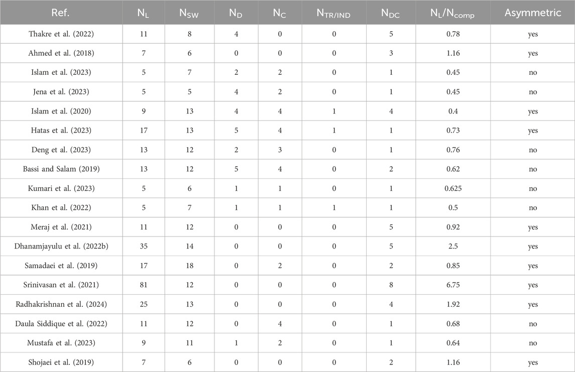
Table 4. Comparison of presented topologies based on component counts and switch utilization.
The focus of the review work was to identify opportunities for further development in multilevel inverter research. Insightful observations are made from the work presented in the paper.
⁃ Asymmetry is used extensively in the development of new reduced switch count topologies and its superiority is documented in the mentioned review article (Vinay Kumar and GowriManohar, 2023). Although it helps to generate more levels with a small number of switches as in the asymmetric CHB, and as evidenced from Table 20, the technique still retains the requirement for isolated active sources. The asymmetry in voltage sources is used in SC topologies such as (Samadaei et al., 2019) and others of the same type. It will be noticed that such topologies only use the additive operations possible for asymmetric topologies, to the exclusion of subtractive operations as in [56]. Including the subtraction of asymmetric voltage sources has the potential to generate more levels, especially in switched capacitor topologies, eliminating the need for isolated DC sources, and development in this direction can yield positive outcomes.
⁃ (Khan et al., 2022) incorporates soft charging for the single boost capacitor, resulting in reduced losses during capacitor charging. SC topologies with more than one capacitor level, such as in (Deng et al., 2023), do not employ any soft charging. Although the voltage ripples may be low by design, the more levels there are in the topology, the more losses we can expect from hard charging of these capacitors. The topologies can benefit from including soft charging for all switched capacitors involved. Development in this area can yield higher efficiency and elimination of deleterious high-inrush capacitor currents.
⁃ Resonant charging is widely adopted for SC converters (Zhu et al., 2021; Zhu et al., 2023), and this is possible because they have a fixed voltage transfer ratio and are usually operated with a fixed duty cycle. On the contrary, SC multilevel inverters have a sinusoidal variable instantaneous voltage transfer ratio (or variable duty cycle), and this makes achieving fully soft charging challenging. The frequent mismatch resulting from the change in duty cycle in HFPWM will equate to power loss during capacitor charging, as shown in Eq. 1. NLC modulation is based on comparison of the reference signal to constant values, and the output waveform only switches to the next voltage level if the comparison yields above a midpoint threshold. Because the modulation is carried out at low frequency, the output voltage level is held for considerably longer time compared to HFPWM and presents an opportunity to explore resonant switched capacitor charging. If achieved, this can result in highly efficient SC multilevel inverters.
⁃ Many SC MLIs have the capacitors charged to multiples of the source voltage, translating to the use of larger capacitors as the gain and output power capacity of the inverter is increased. This results in the use of expensive capacitors. Charging the capacitors to a fraction of the source voltage will result in the use of smaller, low voltage and less costly capacitors. However, this will require voltage clamping or other voltage charge control mechanisms which can be costly. The benefits can be weighed against the cost, depending on the target application. In (45), it was demonstrated that power processing for an asymmetric configuration of {1:2:6} in the asymmetric CHB is 4.2% for the first source, 15.8% for the second source and 80% for the third voltage source. Effectively, the first two voltage sources are primarily for waveform quality improvement. If we assign the first two sources to be capacitors, then we can expect to use smaller and low voltage capacitors. Low power processing can lead to more efficient inverters. Furthermore, because the capacitor will not be isolated, it will be possible to retain modularity, which is lost in the asymmetric CHB.
⁃ An interesting research opportunity is to experiment the development of a PUC7 with inherent capacitor voltage balancing and voltage gain. Eliminating the requirement for auxiliary circuits or an additional voltage source. The combinations of a sensor-less self-balancing PUC5 in (66) and reversal of the second voltage source, the capacitor in this case, (Shojaei et al., 2019), could yield a PUC7 with a gain of 1.5. This however may require 2 additional cross switches in the middle cell. Other high level implementations of the PUC employ sophisticated model-predictive modulation method and sensors such as the hybrid PUC in (Sorto-Ventura et al., 2020) are unattractive for industrial use because of the high complexity.
6 Conclusion
The focus of this work was to review reduced switch count and hybridized improvement types and identify challenges and opportunities to conduct research and development to improve multilevel inverters. The merits and drawbacks of classical topologies have been reviewed and presented as the primary motivation for the advancement and development of new reduced switch count and hybrid multilevel inverters. It is observed that even in the recent topologies, there still exist some challenges and opportunities for further development of multilevel inverters. The use of asymmetry has been a crucial technique in reducing the number of switches, and topologies with the highest output level count to the number of switches are asymmetric. However, asymmetric topologies have increased cost and complexity as they require many isolated active voltage sources. Elimination of additional active sources prompts the use of switched capacitors that employ the full set of operations applicable to asymmetric MLIs, addition, and subtraction of voltage sources. This remains unexplored in SC topologies and has the potential to achieve a high switch utilization as it does in isolated voltage source topologies. The problem of high inrush currents in multi-capacitor SC inverters still needs to be resolved with the developmemt of new topologies involving many capacitors. Resonant charging of capacitors in multilevel converters remains a challenge because of the high-frequency variable voltage transfer ratio. Fundamental frequency-modulated topologies present an opportunity to explore the resonant charging of the switched capacitors. The authors intend to explore the opportunities presented in this review article for further research and development and hope it to be helpful to other researchers as well.
Author contributions
BM: Conceptualization, Investigation, Project administration, Resources, Visualization, Writing–original draft, Writing–review and editing. RS: Supervision, Writing–review and editing. LA: Supervision, Writing–review and editing.
Funding
The author(s) declare that no financial support was received for the research, authorship, and/or publication of this article.
Conflict of interest
The authors declare that the research was conducted in the absence of any commercial or financial relationships that could be construed as a potential conflict of interest.
Publisher’s note
All claims expressed in this article are solely those of the authors and do not necessarily represent those of their affiliated organizations, or those of the publisher, the editors and the reviewers. Any product that may be evaluated in this article, or claim that may be made by its manufacturer, is not guaranteed or endorsed by the publisher.
References
Abarzadeh, M., Vahedi, H., and Al-Haddad, K. (2019). Fast sensor-less voltage balancing and capacitor size reduction in PUC5 converter using novel modulation method. IEEE Trans. Industrial Inf. 15, 4394–4406. doi:10.1109/TII.2019.2893739
Abd Halim, W., Ganeson, S., Azri, M., and Tengku Azam, T. N. A. (2016). Review of multilevel inverter topologies and its applications. J. Telecommun. Electron. Comput. Eng. (JTEC). Available at: https://jtec.utem.edu.my/jtec/article/view/1278.
Ahmad, M., Khan, J. A., Khan, H., Izaz, M., Hayat, Y., and Ali, L. (2024). Designing of different high efficiency diode clamped multilevel inverters and their performance analysis. Available at: https://core.ac.uk/download/234685392.pdf (Accessed February 1, 2024).
Ahmed, M., Sheir, A., and Orabi, M. (2018). Asymmetric cascaded half-bridge multilevel inverter without polarity changer. Alexandria Eng. J. 57, 2415–2426. doi:10.1016/j.aej.2017.08.018
Ashok Kumar, L., Albert Alexander, S., and Rajendran, M. (2021). in Power electronic converters for solar photovoltaic systems. Editors L. Ashok Kumar, S. Albert Alexander, and M. Rajendran (Academic Press) xvii–xviii. doi:10.1016/B978-0-12-822730-5.02001-8
Atar, T., Balci, S., and Kayabasi, A. (2023). Determination of output current THD of multilevel inverter by ANN. Measurement 210, 112525. doi:10.1016/j.measurement.2023.112525
Barnawi, A. B., Alfifi, A. R. A., Elbarbary, Z. M. S., Alqahtani, S. F., and Shaik, I. M. (2023). Review of multilevel inverter for high-power applications. Front. Eng. Built Environ. 4, 77–89. doi:10.1108/FEBE-05-2023-0020
Barros, L. A. M., Martins, A. P., and Pinto, J. G. (2022). A comprehensive review on modular multilevel converters, submodule topologies, and modulation techniques. Energies 15, 1078. doi:10.3390/en15031078
Barzegarkhoo, R., Vosoughi, N., Zamiri, E., Kojabadi, H. M., and Chang, L. (2016). A cascaded modular multilevel inverter topology using novel series basic units with a reduced number of power electronic elements. J. Power Electron. 16, 2139–2149. doi:10.6113/JPE.2016.16.6.2139
Bassi, H. M., and Salam, Z. (2019). A new hybrid multilevel inverter topology with reduced switch count and dc voltage sources. Energies, MDPI 12, 977. doi:10.3390/en12060977
Bhaskar, M. S., Meraj, M., Iqbal, A., Ben-Brahim, L., Padmanaban, S., and Abu-Rub, H. (2020). EKθ multilevel inverter - a minimal switch novel configuration for higher number of output voltage levels. IET Power Electron. 13, 2804–2815. doi:10.1049/iet-pel.2019.0945
Bressan, M. V., Rech, C., and Batschauer, A. L. (2019). Design of flying capacitors for n-level FC and n-level SMC. Int. J. Electr. Power Energy Syst. 113, 220–228. doi:10.1016/j.ijepes.2019.05.030
Bughneda, A., Salem, M., Richelli, A., Ishak, D., and Alatai, S. (2021). Review of multilevel inverters for PV energy system applications. Energies 14, 1585. doi:10.3390/en14061585
Busarello, T. D. C., De Sousa Marcondes Reuter, A. L., Péres, A., and Godoy Simões, M. (2018). Understanding the staircase modulation strategy and its application in asymmetric cascaded H-bridge multilevel inverter. IEEE Ind. Appl. Soc. Annu. Meet. doi:10.1109/IAS.2018.8544721
Busarello, T. D. C., De Sousa Marcondes Reuter, A. L., Peres, A., and Simoes, M. G. (2019). Understanding the staircase modulation strategy and its application in both isolated and grid-connected asymmetric cascaded H-bridge multilevel inverters. IEEE Trans. Industry Appl. 55, 5371–5382. doi:10.1109/TIA.2019.2927189
Chang-xin, M., Li-ping, S., Tai-xu, W., and Cheng-bao, C. (2009). Flying capacitor multilevel inverters with novel PWM method. Procedia Earth Planet. Sci. 1, 1554–1560. doi:10.1016/j.proeps.2009.09.240
Cherkaoui Jaouad, N., Chaikhy, H., Belhora, F., and Hajjaji, A. (2022). Comparison between two levels and multi-level (NPC and Cascad) inverters. Mater. Today; Proc. 66, 162–180. doi:10.1016/j.matpr.2022.04.338
Chitra, S., and Valluvan, K. R. (2020). Design and implementation of cascaded H-Bridge multilevel inverter using FPGA with multiple carrier phase disposition modulation scheme. Microprocess. Microsystems 76, 103108. doi:10.1016/j.micpro.2020.103108
Choudhury, S., Bajaj, M., Dash, T., Kamel, S., and Jurado, F. (2021). Multilevel inverter: a survey on classical and advanced topologies, control schemes, applications to power system and future prospects. Energies 14, 5773. doi:10.3390/en14185773
Daula Siddique, M., Prathap Reddy, B., Iqbal, A., Sarwar, A., Ahmed Memon, M., Dahri, K., et al. (2022). A new design of active NPC converter topology with higher voltage gain for solar PV applications. Sustain. Energy Technol. Assessments 54, 102850. doi:10.1016/j.seta.2022.102850
Deng, Z., Zhu, X., Duan, J., Ye, J., and Wang, Y. (2023). A multilevel switched capacitor inverter with reduced components and self-balance. Appl. Sci. MPDI 13, 8955. doi:10.3390/app13158955
Dhanamjayulu, C., Rudravaram, V., and Sanjeevikumar, P. (2022b). Design and implementation of a novel 35-level inverter topology with reduced switch count. Electr. Power Syst. Res. 212, 108641. doi:10.1016/j.epsr.2022.108641
Dhanamjayulu, C., Sanjeevikumar, P., and Muyeen, S. M. (2022a). A structural overview on transformer and transformer-less multi level inverters for renewable energy applications. Energy Rep. 8, 10299–10333. doi:10.1016/j.egyr.2022.07.166
Es-Saadi, M., Khafallah, M., Chaikhy, H., Brik, A. A., and Khoukh, A. (2018). Using the five-level NPC inverter to improve the FOC control of the asynchronous machine. IEEE Xplore. doi:10.1109/IRSEC.2017.8477356
Ghani, A. A., Ahmed, Q. S., Ihsan, M., and Yang, S. (2023). Design of three-level NPC AC/DC bidirectional converter using model predictive controller for DC bus voltage stability of subway. Eng. Proc. 46(1), 37. doi:10.3390/engproc2023046037
Harin, M. M., Vanitha, V., and Jayakumar, M. (2017). Comparison of PWM techniques for a three level modular multilevel inverter. Energy Procedia 117, 666–673. doi:10.1016/j.egypro.2017.05.180
Hatas, H., and Almali, M. N. (2023). Design and control of a novel topology for multilevel inverters using high frequency link. Electr. Power Syst. Res. Elsevier 221, 109458. doi:10.1016/j.epsr.2023.109458
Humayun, M., Khan, M. M., Muhammad, A., Xu, J., and Zhang, W. (2020). Evaluation of symmetric flying capacitor multilevel inverter for grid-connected application. Int. J. Electr. Power Energy Syst. 115, 105430. doi:10.1016/j.ijepes.2019.105430
Islam, M. T., Alam, M. A., Lipu, M. S. H., Hasan, K., Meraj, S. T., Masrur, H., et al. (2023). A single DC source five-level switched capacitor inverter for grid-integrated solar photovoltaic system: modeling and performance investigation. Sustainability 15, 8405. doi:10.3390/su15108405
Islam, M. T., Islam, M. R., and Muttaqi, K. M. (2020). A novel high frequency magnetic linked reduced switch multilevel inverter for solar photovoltaic systems. Hobart, Australia: Australasian Universities Power Engineering Conference AUPEC. Available at: https://ieeexplore.ieee.org/document/9344497 (Accessed February 11, 2024).
Jana, J., Saha, H., and Das Bhattacharya, K. (2017). A review of inverter topologies for single-phase grid-connected photovoltaic systems. Renew. Sustain. Energy Rev. Elsevier 72, 1256–1270. doi:10.1016/j.rser.2016.10.049
Jayakumar, V., Chokkalingam, B., and Lange Munda, J. (2021). A comprehensive review on space vector modulation techniques for neutral point clamped multi-level inverters. IEEE Access 9, 112104–112144. doi:10.1109/ACCESS.2021.3100346
Jena, K., Kumar, D., Hemanth Kumar, B., Janardhan, K., Singh, A. R., Naidoo, R., et al. (2023). A single DC source generalized switched capacitors multilevel inverter with minimal component count. Compon. Count 2023, 1–12. doi:10.1155/2023/3945160
Jiang, W., Gao, Y., Wang, J., and Wang, L. (2017). A hybrid modulation strategy with reduced switching losses and neutral point potential balance for three-level NPC inverter. J. Electr. Eng. Technoly, Korea Sci. 12, 738–750. doi:10.5370/JEET.2017.12.2.738
Kabalcı, E. (2021). Multilevel inverters: introduction and emergent topologies. Academic Press, 2–28.
Kala, P., and Arora, S. (2017). A comprehensive study of classical and hybrid multilevel inverter topologies for renewable energy applications. Renew. Sustain. Energy Rev. 76, 905–931. doi:10.1016/j.rser.2017.02.008
Kannan, C., Mohanty, N. K., and Selvarasu, R. (2017). A new topology for cascaded H-bridge multilevel inverter with PI and Fuzzy control. Energy Procedia 117, 917–926. doi:10.1016/j.egypro.2017.05.211
Khan, M. N. H., Barzegarkhoo, R., Siwakoti, Y. P., Khan, S. A., Li, L., and Blaabjerg, F. (2022). A new switched-capacitor multilevel inverter with soft start and quasi resonant charging capabilities. Int. J. Electr. Power and Energy Syst. 135, 107412. doi:10.1016/j.ijepes.2021.107412
Kieferndorf, F., Basler, M., Fabian, J., and Coccia, A. (2000). The five-level converter. ABB. Available at: https://library.e.abb.com/public/8c65d75ced8b80d6c1257988005b5c69/41-46%201m127_ENG_72dpi.pdf (Accessed February 1, 2024).
Kumar, K. B., Bhanuchandar, A., Vamshy, D., Gurunath, H., Mohandas, A., and Palle, K. (2022). A nearest level control technique for an asymmetric source configuration of multi-level inverter topology. Int. J. Eng. Sci. Technoly 14, 1–9. doi:10.4314/ijest.v14i3.1S
Kumar Gupta, K., and Bhatnagar, P. (2018). Multilevel inverters-conventional and emerging topologies and their control. Academic Press.
Kumari, A., Gopal, Y., Kumar Dhaked, D., Panda, K. P., and Vijaya Kumar, Y. N. (2023). A single source five-level switched-capacitor based multilevel inverter with reduced device count. e-Prime-Advances Electr. Eng. Electron. Energy, Elsevier 5, 100235. doi:10.1016/j.prime.2023.100235
Laamiri, S., Ghanes, M., Amet, L., and Santomenna, G. (2017). Direct control strategy for a three phase eight-level flying-capacitor inverter. IFAC-PapersOnLine 50, 15786–15791. doi:10.1016/j.ifacol.2017.08.2315
Lewicki, A., Odeh, C., and Morawiec, M. (2023). Space vector pulsewidth modulation strategy for multilevel cascaded H-bridge inverter with DC-link voltage balancing ability. IEEE Trans. Industrial Electron. 70, 1161–1170. doi:10.1109/TIE.2022.3158005
Mayorga, N., Roncero-Clemente, C., Llor, A. M., and Husev, O. (2021). A simple space vector modulation method with DC-link voltage balancing and reduced common-mode voltage strategy for a three-level T-type quasi-Z source inverter. IEEE Access 9, 82747–82760. doi:10.1109/ACCESS.2021.3087035
Mehta, S., and Puri, V. (2022). A review of different multi-level inverter topologies for grid integration of solar photovoltaic system. Renew. Energy Focus 43, 263–276. doi:10.1016/j.ref.2022.10.002
Meraj, S. T., Yahaya, N. Z., Hasan, K., and Masaoud, A. (2021). A hybrid T-type (HT-type) multilevel inverter with reduced components. Ain Shams Eng. J. 12, 1959–1971. doi:10.1016/j.asej.2020.12.010
Mustafa, S., Sarwar, A., Tariq, M., Ahmad, S., and Mahmoud, H. A. (2023). Development and control of a switched capacitor multilevel inverter. Energies 16, 4269. doi:10.3390/en16114269
Odeh, C. I., Lewicki, A., and Morawiec, M. (2021). “A single-carrier-based pulse-width modulation template for cascaded H-bridge multilevel inverters,” in IEEE access. doi:10.1109/ACCESS.2021.3065743
Oghorada, O. J. K., Zhang, L., Esan, B. A., and Dickson, E. (2019). Carrier-based sinusoidal pulse-width modulation techniques for flying capacitor modular multi-level cascaded converter. Heliyon 5, e03022. doi:10.1016/j.heliyon.2019.e03022
Radhakrishnan, A., Arasan, E. S., Ramalingam, B. C., and Chandrasekaran, K. (2024). A new asymmetric H-6 structured multilevel inverter with reduced power components. Symmetry 16, 72. doi:10.3390/sym16010072
Ramu, V., Satish Kumar, P., Srinivas, G. N., and Lspwm, PSPWM (2022). LSPWM, PSPWM and NLCPWM on multilevel inverters with reduced number of switches. Mater. Today Proc. 54, 710–727. Available from. doi:10.1016/j.matpr.2021.10.410
Rodriguez, J., Franquelo, L. G., Kouro, S. L., JosÉ, I. P., Prats, R. C., Perez, M. M., et al. (2009). “Multilevel converters: an enabling technology for high-power applications,” in Proceedings of the IEEE, 1786–1817. doi:10.1109/JPROC.2009.2030235
Rotella, M., Peñailillo, G., Pereda, J., and Dixon, J. (2006). PWM method to eliminate power sources in a nonredundant 27-level inverter for machine drive applications. Montreal: IEEE International Symposium on Industrial Electronics. doi:10.1109/ISIE.2006.295789
Samadaei, E., Kaviani, M., Iranian, M., and Pouresmaeil, E. (2019). The P-type module with virtual dc links to increase levels in multilevel inverters. Electronics 8, 1460. Available from. doi:10.3390/electronics8121460
Sedaghati, A., Horrillo-Quintero, P., Sánchez-Sáinz, H., and Fernández-Ramírez, L. M. (2022). Staircase modulation improvement to balance output power of stages of cascade H-bridge multilevel inverter. Comput. Electr. Eng. 103, 108331. Available from. doi:10.1016/j.compeleceng.2022.108331
Shojaei, A. A., Najafi, B., and Vahedi, H. (2019). Standalone operation of modified seven-level packed U-cell (MPUC) single-phase inverter. Electronics 8, 268. doi:10.3390/electronics8030268
Sorto-Ventura, K. R., Abarzadeh, M., Al-Haddad, K., and Dessaint, L. A. (2020). 23-level single DC source hybrid PUC (H-PUC) converter topology with reduced number of components: real-time implementation with model predictive control. IEEE Open J. Industrial Electron. Soc. 1, 127–137. Available from. doi:10.1109/OJIES.2020.3007989
Srinivasan, G. K., Rivera, M., Loganathan, V., Ravikumar, D., and Mohan, B. (2021). Trends and challenges in multi-level inverter with reduced switches. Electronics 10, 368. Available from. doi:10.3390/electronics10040368
Stöttner, J., Hanzl, C., and Endisch, C. (2022). Extensive investigation of symmetrical and asymmetrical cascaded multilevel inverters for electric vehicle applications. Electr. Power Syst. Res. 209, 108009. Available from. doi:10.1016/j.epsr.2022.108009
Tamilvani, P., and Valluvan, K. R. (2012). Hybrid modulation technique for cascaded multilevel inverter for high power and high quality applications in. Renew. Energy Syst. Available at: http://www.irphouse.com/ijeee/ijeev5n1_6.pdf (Accessed February 11, 2024).
Thakre, K., Mohanty, K. B., Kommukuri, V. S., Chatterjee, A., Nigam, P., and Gupta, S. K. (2022). Modified cascaded multilevel inverter for renewable energy systems with less number of unidirectional switches. Energy Rep. Elsevier 8, 5296–5304. Available from. doi:10.1016/j.egyr.2022.03.167
Ullah, S., Haidar, A. M. A., Hoole, P., Zen, H., and Ahfock, T. (2020). The current state of Distributed Renewable Generation, challenges of interconnection and opportunities for energy conversion based DC microgrids. J. Clean. Prod. 273, 122777. doi:10.1016/j.jclepro.2020.122777
Vakacharla, V. R., Gnana, K., Xuewei, P., Narasimaharaju, B. L., Bhukya, M., Banerjee, A., et al. (2020). State-of-the-art power electronics systems for solar-to-grid integration. Sol. Energy 210, 128–148. Available from. doi:10.1016/j.solener.2020.06.105
Vincotech, F. (2024). Capacitor inverter the advantages and operation of flying capacitor inverter. Available at: https://www.vincotech.com/fileadmin/user_upload/content_media/documents/pdf/support-documents/technical-papers/Vincotech_TP_Solar_The_Advantages_and_Operation_of_Flying_Capacitor_Inverter_2020.pdf (Accessed February 11, 2024).
Vinay Kumar, N. V., and GowriManohar, T. (2023). A comprehensive survey on reduced switch count multilevel inverter topologies and modulation techniques. J. Electr. Syst. Inf. 10, 3. Available from. doi:10.1186/s43067-023-00071-8
Wikipedia (2024). Total harmonic distortion. Available at: https://en.wikipedia.org/wiki/Total_harmonic_distortion (Accessed April 4, 2024).
Zhu, Y., Ye, Z., and Pilawa-Podgurski, R. C. N. (2021). “Modeling and analysis of resonant switched-capacitor converters with finite terminal capacitances,” in 2021 IEEE 22nd workshop on control and modelling of power electronics (COMPEL), Available from. doi:10.1109/COMPEL52922.2021.9646020
Keywords: hybrid topologies, multilevel inverters, photovoltaic systems, reduced switch count topology, renewable energy
Citation: Mosepele B, Samikannu R and Amuhaya L (2024) A structural review on reduced switch count and hybrid multilevel inverters. Front. Energy Res. 12:1396149. doi: 10.3389/fenrg.2024.1396149
Received: 05 March 2024; Accepted: 11 June 2024;
Published: 09 July 2024.
Edited by:
Terence O’Donnell, University College Dublin, IrelandReviewed by:
Fateh Krim, University Ferhat Abbas of Setif, AlgeriaFei Li, Hefei University of Technology, China
Copyright © 2024 Mosepele, Samikannu and Amuhaya. This is an open-access article distributed under the terms of the Creative Commons Attribution License (CC BY). The use, distribution or reproduction in other forums is permitted, provided the original author(s) and the copyright owner(s) are credited and that the original publication in this journal is cited, in accordance with accepted academic practice. No use, distribution or reproduction is permitted which does not comply with these terms.
*Correspondence: Boikhutso Mosepele, bW9yb2JhbmFAZ21haWwuY29t