 Hajer Gaied1
 Flah Aymen
 Habib Kraiem
94% of researchers rate our articles as excellent or good
Learn more about the work of our research integrity team to safeguard the quality of each article we publish.
Find out more
ORIGINAL RESEARCH article
Front. Energy Res., 23 August 2024
Sec. Process and Energy Systems Engineering
Volume 12 - 2024 | https://doi.org/10.3389/fenrg.2024.1391310
In this study, we performed a detailed simulation of the PIDRN controller associated with a three-phase converter, taking into account different initial battery charging conditions. After introducing the concept of PIDRN and explaining the operation of the three-phase converter, we proceeded to model the system, defining the necessary parameters. We then configured several simulations, varying the initial charging conditions of the battery, and analyzed the numerical results obtained. This comparative analysis revealed variable system performance depending on the initial battery charge level, highlighting advantages and disadvantages in each case. In particular, we found that the PIDRN controller proves to be an optimal choice for this type of converter, thanks to its ability to effectively regulate voltage and current under varying battery charging conditions. We discussed the implications of these findings. In conclusion, this study provides an in-depth overview of the performance of the PIDRN controller in a three-phase converter context and highlights the importance of taking into account the initial battery conditions in the design and optimization of energy control.
Rising demand for clean energy has led to the use of renewable energy. Energy sources (RES) are a possible approach to participating in energy generation. The elimination of hazardous techniques for energy production is becoming a current necessity worldwide. Traditional methods of energy production have resulted in significant global environmental impacts, resulting in high and costly costs. Renewable energy sources (RES) have proven to be a boon because of their cost-effectiveness and respect for the environment. Historically, power plants were powered by crude oil (Zhang et al., 2023; Rasouli Heikalabad, 2024). Recently, it has been found that the massive consumption of crude oil has finally led to the scarcity of crude oil, and the researchers have developed hybrid energy production systems that can be used with natural gas and crude oil. However, there was a decrease in power plant efficiency due to the hybrid use of fuel, which eventually led to the scarcity of natural gas. However, there was a decrease in power plant efficiency due to the hybrid use of fuel, which ultimately contributed to the lack of natural gas. In addition, the use of fossil fuels has had a significant impact on the environment and has become an expensive method of generating electricity. Thus, the emergence of the concept of renewable energy sources is examined in depth and put into practice. Given their abundance and absence of adverse environmental effects.
Converters play a crucial role in any hybrid renewable energy system as they maintain voltage stability during fluctuation periods. The stability of the power converter and its control technique play a crucial role in the energy quality of renewable energy systems. Let’s take the example of a thrust converter, which is widely used in MPPT solar systems. A controlled closed-loop boost converter can keep the DC link voltage stable by increasing the low input voltage of the photovoltaic cells (Gao et al., 2022). However, the majority of conventional converters and control methods have several disadvantages that minimize their efficiency in HRES systems. Thus, recently, researchers have begun to focus on the creation of improved DC-DC converters and effective control techniques (Grisales-Noreña et al., 2019). DC-DC electronic converters offer greater efficiency than traditional power conversion methods. Conventional methods using transformers and rectifiers often have many disadvantages while being extremely expensive. In contrast, power converters are small in size, have a limited number of components, and are neutral to voltage fluctuations and electromagnetic interference (EMI). In addition, it is easy to filter the output of the power converter using a simple filter and adjust or manipulate it using a control technique adapted to the requirements of the system (Song et al., 2022a; Zhang et al., 2021).Therefore, by enabling effective conversion and management of the DC voltage generated by renewable energy sources, integration of energy storage systems, and performance optimization of energy systems, DC-DC converters play a crucial role in renewable energy applications. Enhancing energy efficiency, downsizing converters, and integrating renewable energy sources more deeply into power systems are the main goals of this field’s research and development (Song et al., 2022b). These two varieties of DC-DC converters are Energy storage systems, industrial and electrical applications, as well as renewable energy sources, can all make use of these insulated and non-insulated varieties. The particular needs of the application in terms of insulation, voltage regulation, power, and other criteria will determine whether to use an insulated or uninsulated converter (Fei et al., 2024).The interlaced DC-DC converter, often referred to as the cross-switched DC-DC converter, is one kind of uninsulated converter that is used to change a DC voltage from one level to another. Its primary function is to alter a DC power source’s voltage in order to satisfy the demands of an electronic system. A switch, an inductor, and a capacitor are often included in each of the two conversion stages that make up an interlaced DC-DC converter. Efficient voltage conversion is achieved by synchronizing and operating in alternate phases. When compared to traditional DC-DC converters, the primary benefit of an interlaced DC-DC converter is its capacity to minimize energy losses. The energy held in the capacitors and inductors can be shared by leveraging the link between the two conversion stages, which improves energy efficiency. Combining various renewable energy sources into a system: Interlaced DC-DC converters work well for combining various renewable energy sources (Deng et al., 2023; Zhu et al., 2024). They can effectively handle various output voltages and transform them into a common voltage or one that is tailored to the needs of the entire system (Li et al., 2022). Improving voltage regulation: The output voltage is more optimally regulated when using layered DC-DC converters. They can maintain correct and steady voltage, which is necessary to guarantee the dependable operation of associated devices and loads, by employing sophisticated control techniques (Zhou et al., 2024; Shen et al., 2023). Diminished dimensions and weight of the system: Passive components like inductors and capacitors can have their sizes and weights decreased by using interlaced DC-DC converters that operate at high switching frequencies. This enables the creation of lighter and more compact renewable energy systems, which is especially helpful for installations with limited space or mobile applications. The advancement of technology has led to a greater dependence on electrical products for daily needs. Achieving sustainable growth in society and the economy requires striking a balance between energy use and environmental conservation more than ever. For example, using fossil fuels or natural gas to generate thermal power causes a great deal of environmental harm, as Figure 1 illustrates.
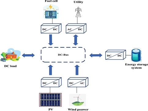
Figure 1. Energy storage system in DC microgrid.
In this work, we combined a short conversion duration with a control technique created for the suggested topologies of the DC-DC converter. The terminal voltages of renewable energy sources are usually low and change with time. Therefore, in order to offer reliable electrical energy, it is standard procedure to interface with the DC bus using a bidirectional DC-DC converter with a high conversion ratio. The converter must lower the load current in order to ensure a smooth power transfer; however, this has the unforeseen consequence of restricting the power capacity during conversion. This article also assesses the energy conversion between operating modes to offer a rapid energy conversion method (Fu et al., 2023).
This diagram illustrates the primary distinctions between a neural network-based PID controller and a conventional PID controller with regard to their structure, optimization technique, performance, flexibility, computation time, resilience, and implementation cost (Feng et al., 2024). When selecting the controller that is most appropriate for a particular battery state of charge management application, several distinctions must be considered Figure 2.
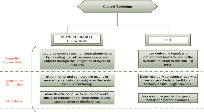
Figure 2. Traditional PID and PID controller with neural networks performance and adaptability organization for battery charge state management.
The purpose of this work is to compare the effectiveness and versatility of two control strategies the conventional PID controller and the PID controller with neural networks—for managing battery state of charge (SOC) in renewable energy systems.
The effectiveness of the two strategies is compared in a number of studies under varied circumstances, including changes in system load. The findings demonstrate that while the PID controller with neural networks offers improved accuracy and increased flexibility to changes in operating circumstances, its implementation may necessitate more processing time and resources. This study’s conclusion emphasizes how crucial it is to select the controller that best meets the unique requirements of each application, taking into account factors like cost, performance, adaptability, and computation time.
These days, several DC-DC converters are employed to change the input voltage according to the requirements of the application. DC-DC converters are generally classified into two basic types: isolated and non-isolated. Because isolated converters use a transformer to divide the input and output sides of the DC-DC converter, they have galvanic isolation. The input has no effect on the output side of the converter because it has a separate ground (Chen et al., 2024). The converter’s output value may have a positive or negative polarity, depending on how it was designed. It can generate a consistent output while operating with a range of inputs. Isolated converters are more costly than non-isolated converters and have significant risks related to leakage inductance, core saturation, thermal impact, high voltage spikes across the switches, and large bulk. Changes made on the input side immediately affect the output sides of the converters since there is no galvanic isolation between the input and output sides in a non-isolated converter architecture. They have fewer components than the isolated converter topology. They do, however, also have a few minor issues that require attention, like as excessive duty cycle ratio, insufficient voltage gain, and additional circuitry for optimal operation. The advantages and disadvantages of every class of converter topologies are different. The application’s requirements serve as the basis for the decision. The power converter family is shown in Figure 3, with the traditional converter topologies in both groups highlighted.
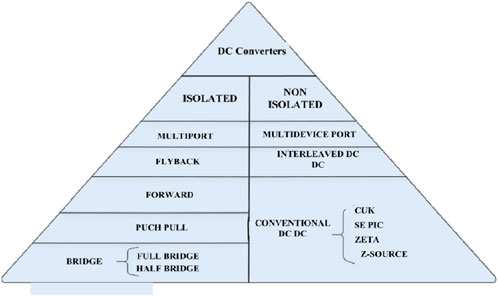
Figure 3. Classification of DC converters.
Because of their superior performance, cost-effectiveness, structural simplicity, and higher efficiency, non-isolated interleaved DC-DC converters have nearly completely replaced conventional converters in renewable energy applications. For this reason, the configurational and performance analysis of these converters is extremely important. The application of control techniques, such as proportional integral (PI) modeling and control of traditional non-isolated interleaved converter topologies, was also thoroughly covered in this paper. It did not, however, provide any additional control methods for DC-DC converter functioning beyond PI modeling.
One of the converters used most frequently when charging or discharging a battery is the elevating converter, which is well-liked for its excellent conversion range and ease of usage (Xue et al., 2017; Zhu et al., 2024). This kind of converter allows the battery voltage levels to be adjusted to the DC bus voltage levels by maintaining a steady voltage level and controlling the disruptions caused by connecting and disconnecting loads and energy sources. However, the battery receives the ripple in the switch’s current, which leads to power losses and battery deterioration (Bai et al., 2022; Syah et al., 2022).
Interleaved converters for high-power, high-current applications, like energy storage systems, general-purpose motor drives, and renewable energy conversion systems, have been the subject of numerous publications in the literature (Wang et al., 2023).
The output power can even approach tenths of a kilowatt when N phases consisting of semiconductors and filter components are employed. Because the operating frequency is now an integer multiple of the switching frequency, this leads to reduced filter element size. The drive signals of the active switches must be phase-shifted by 360°/N, which is easily accomplished by using low-cost microcontrollers instead of complex analog circuitry. The common interleaved bidirectional dc-dc converter is a simple solution for the application addressed in this study, as was already mentioned (Mayer et al., 2021; Duan et al., 2023). A two-phase structure is shown in Figure 4, where V1 and V2 represent the DC link and the SC, respectively (Zhang et al., 2023). Moreover, I1 and I2 are the corresponding currents across the SC and the dc link, whereas
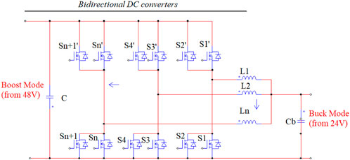
Figure 4. Interleaved bidirectional DC DC converter.
Table 1 depicts the interleaved bidirectional DC-DC converter tree phase employing n parallel-connected Mosfets. Eight power switches (
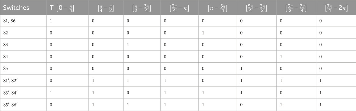
Table 1. Switches signal commands three phases converter.
Energy moves from the battery side to the DC bus side when the proposed converter is operating in step-up mode (boost), where DH is the duty cycle of the gate signals S1–S6. Energy is transferred from the DC bus to the battery side in step-down mode (buck), where DL is the duty cycle of the gate signals S1′–S6′.
The main waveforms for the duty cycle range that belongs to [0,0.25].
First stage [t0 - t1]: (
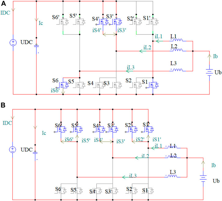
Figure 5. Equivalent circuits of boost mode using interleaved converter three phases. (A): first stage, (B): second stage.
Inductor
Second stage [t1 − t2]: (
Through;
With n = 1,2,3 and m = 2,3,6.
Buck mode features eight steps in one switching time and two operation regions, just like boost mode. The circuit is symmetric, so just the fourth period is examined.
The main waveforms for the duty cycle range that belongs to [0,0.25].
First stage [t0 − t1]: (S3, S4,
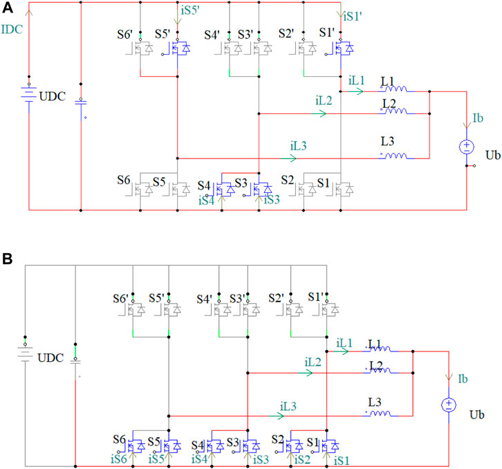
Figure 6. Equivalent circuits of buck mode using interleaved converter three phases. (A): first stage, (B): second stage.
As energy from the υDC is stored through the inductor L1stars, its current iL1(t) grows linearly until t1. The voltage UDC- Ub and Ub is delivered to L1, L2 and L3, respectively, and the current iL2(t) continues to fall linearly. The stored energy in L2 is transferred to the load through S3 and S4 as a result. Eqs 5–7, correspondingly, can be used to calculate the instantaneous currents and voltages of L1, L2 and L3.
Second stage
Through
As a result, the instantaneous current/voltage equations for inductor is illustrated in Eq. 8, respectively, and the current through all inductors falls linearly.
With n = 1,2,3 and m = 2,3,5.
The DC for three-phase converter voltage gain can be calculated in boost and buck mode using the following expressions Eq. 9, Eq. 10:
Because of their ability to approximate nonlinear functions, artificial neural networks (ANN) have found widespread use in the estimation and control of nonlinear systems. Moreover, adaptive controllers can be created using the properties of changing the ANN weights. Numerous applications have explored the use of ANN and control together (Sun et al., 2024).
Only the functions of the variables that need to be controlled are employed in the 12 system transfer functions that may be obtained from this state space (Guo and Hu, 2023). The control structure shown in Figure 7 is employed, where it is evident that measuring the three system status variables is required to manage the bus voltage and lower the current ripple in the battery. For a very long time, PID control schemes, which are based on classical control theory, have been extensively utilized for a variety of process control systems. Nevertheless, because these systems have nonlinear characteristics, it is challenging to identify appropriate PID parameter sets. This section covers a new neural network-based system identification scheme and a PID control scheme based on the estimations. The recently presented approach does not require any information on the system Jacobian, making it applicable to nonlinear systems with unknown time-delays (Song et al., 2022). An activation function must be provided to map the neural signal to the output in order to input the neural signal from the neurons in the input layer to the hidden layer for neurotransmission.
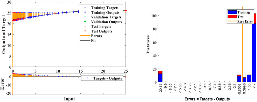
Figure 7. Redes neuronales artificiales.
Network Neural Artificial neural networks are used in PID control to learn from and modify control based on historical data and experiences. A type of machine learning is involved. As they gain knowledge from data, they can automatically modify their parameters. They may therefore gradually adjust to changes in the system. And are frequently more implicit as a result of the neural network’s ability to modify internal weights and biases in order to attain ideal control. Compared to traditional PID, this may make the control process less cross-parent (Sun et al., 2024).The primary distinction is in the control strategy employed. Neural network control is based on machine learning and altering the weights of the neural network to accomplish the desired control, whereas PID is based on mathematical equations and predetermined parameters (Luo et al., 2023; Mohammadzadeh et al., 2024).
The specifics of the application and the properties of the system to be managed will determine which of these two approaches is best, as illustrated by the artificial neural networks Figures 7, 8A.
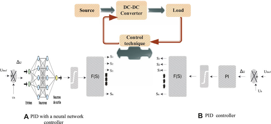
Figure 8. Control system. (A): PID neural network, (B): classic PID.
Two PI controllers are used to regulate the charging and draining of batteries: One is for the generation of reference current, which varies according to the mode of operation (charging or discharging). The other is for battery current control.
The case study that is being given has two modes of operation:
Charging mode: automatic when the DC bus is connected and, as shown in Figure 8B, the control objective set point (of the first PI closed loop) reaches the full voltage of the battery.
Discharging mode: this mode is automatically initiated when the DC bus is disconnected and the first PI closed loop’s control target is changed to load voltage in order to maintain a steady load voltage during discharging.
Measurements were conducted utilizing a DC source connected to a battery in order to verify the PWM functioning and the comparison between the two topologies examined in the preceding sections.
Table 2 displays the configuration of simulation parameter values with fixed DC bus voltage UDC = 48 V, battery voltage Ub = 24 V, and
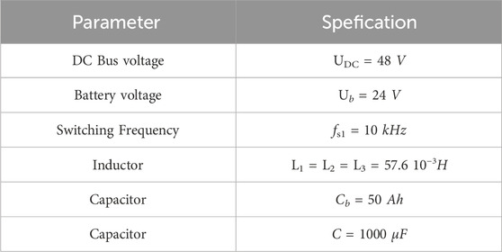
Table 2. Parameters of the experimental system.
PID and PID with neural network are the two battery voltage controllers that are compared using a simulation of an interleaved DC converter with a three-phase parallel MOSFET during discharge and charge. In order to mimic the converter in boost mode (discharge mode) on the 24 V, 50 Ah50 ah low-voltage battery, which is thought to be supplied by the 48-V DC bus voltage, a 4.4 oh resistive load is added. Similarly, a 24-V, 50 AH battery that is charged during operation is linked to the remaining DC bus replacement load. The battery voltage regulation simulation results for the two control topologies for this kind of interleaved converter are displayed in Figure 10.
As demonstrated in Figure 9 this control indicates that the error at the conclusion of the simulation is equal to 0.1 and that the control with the PID is equal to 0.2. Additionally, the RN PID is faster than the standard PID: Quick adaptation: Neural networks have the capacity to pick up on changes in the system and change accordingly. This implies that RN-based controllers, as opposed to traditional PID controllers with set parameters, can respond to changing situations more quickly. Better prediction: By using RNs to forecast future system changes, deviations can be identified and fixed before they happen. This helps to get more precise and quick control. Disruption management: Because RNs are skilled at modeling non-linear systems, they are better equipped to handle unforeseen disruptions.
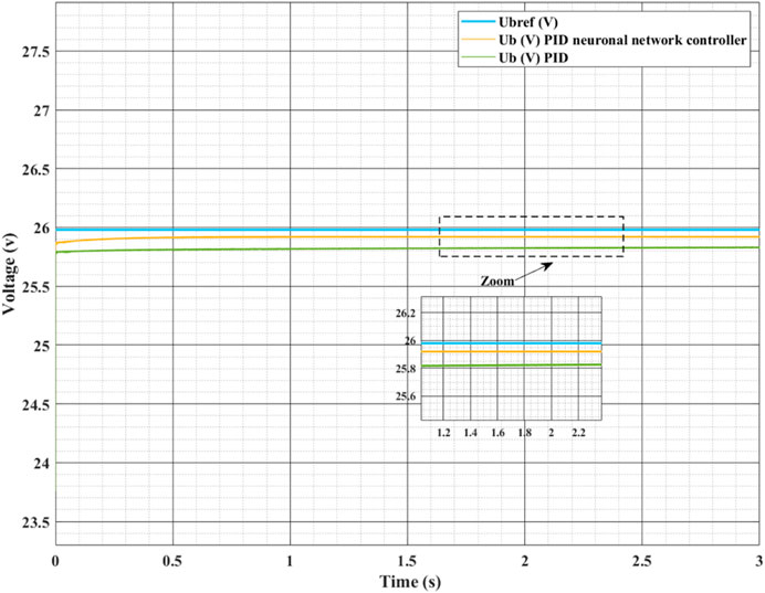
Figure 9. Battery voltage regulation.
When using PID control with neural networks for the three-phase converter in the initial scenario of 40% battery SOC and input voltage, as seen in Figure 10, 11, the battery power output then displays a power of 1,650 w.
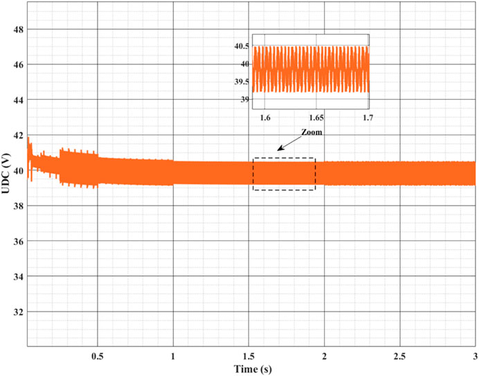
Figure 10. DC voltage.
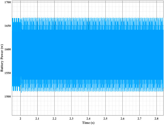
Figure 11. Zoom of Battery power.
However, it should be mentioned that individual system needs and design limitations determine which three-phase interleaved converter is best. The complexity and cost of the system may rise due to the three-phase converter’s potential need for additional components and control. Therefore, prior to selecting the appropriate type of converter, it is crucial to evaluate system requirements, performance standards, and budgetary restrictions. It is crucial to examine a number of factors in order to compare the outcomes and functionality of the parallel MOSFET and the three-phase interleaved DC-DC converter. The number of phases used is where the primary distinction is found. On the other hand, the three-phase converter employs three phases for switching. The phase distribution between the parallel MOSFETs can be affected by the number of phases. This load distribution might affect conduction losses and system efficiency in the case of the three-phase converter, where it is split among three transistors. Additionally, the number of phases can affect battery status control. A system’s dynamics, stability, and accuracy of control can all be affected differently by initial battery SoC values. There are certain simulations and studies that are needed in order to better comprehend the distinctions between these two scenarios. It will be feasible to ascertain the benefits and drawbacks of each strategy by analyzing the dynamic performance, efficiency, stability, and regulation of the SoC for various configurations and starting SoC levels using two distinct battery voltage management approaches. This will allow you to select the configuration that best suits the unique needs of the battery control system and energy conversion. It's crucial to remember that particular outcomes could vary depending on the simulation settings, battery properties, and converter parameters.
In Figure 12A and in Figure 12B, the initial value of the state of charge (SoC) of 20% is first taken. It can be observed that when the three-phase converter is operated with PID control using neural networks, the SoC value increases beyond 20.02; however, when the battery is charged or discharged, the SoC value decreases and reaches 20.01. The values for SoC 35% are equal. In addition, the three-phase converter increases to more than 35.01% for PID control using neural networks, whereas the other control’s SoC value decreases to less than 35.01%.
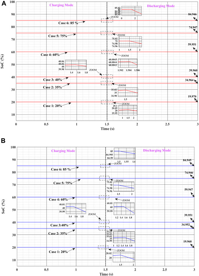
Figure 12. State of Charge level of Li-ion battery during charging and discharging mode for different % soc initiative with three phases converters: (A) PID with neuronal network controller; (B) Traditional PID controller.
In the alternative scenario, we propose PID control for closed-loop battery voltage regulation using neural networks. With a three-phase DC converter, a battery with an initial value of 40% SoC may require more charging and discharging to reach the target value of more than 40.01% when charging and 39.96% when discharging. As for PID, we note that the value reaches more than 40% when charging the battery and 35.95% when charging the battery.
The simulation results guarantee the same interpretation when the initial value of the SoC is large, i.e., 60% and more. In this scenario, the three-phase converter with PID control using neural networks increased to more than 60.005% when under load and 59.95% when under discharge than PID. Additionally, it is noted that for PID neural networks and PID control. , the maximum value in the case of 75% load becomes 75.001% in the case of charge and less than 74.95% in the case of discharge. Specifically, the SoC value reaches 85.0002% with PID control network neurons in the case of charge and less than 84.95% in the case of discharge. Concluded that the suggested three-phase converter for battery charging with PID control neural networks can change based on the different starting values of the SoC battery with a big configuration when using PID control neural networks compared to the other. The three-phase converter with PID regulation and neural network is more efficient and has a better SoC due to its decreased energy loss. In fact, the three-phase converter may store a lot more energy in the battery for the same amount of energy provided by the power source, leading to a greater SoC. It's crucial to remember that RN regulation can be trickier to set up and learn than traditional PID controller regulation. Large data sets and a learning phase might be necessary, which could be a drawback in some situations. Hence, the decision between these two approaches will be based on the particular needs of your system, the accessibility of learning data, and the intricacy of the intended regulation. Overall, the effectiveness of RN regulation in your simulation shows its benefits for modeling complex systems and adaptability, which makes it a good option for battery regulation applications.
Tables 3, 4 illustrate the SOC gains for a PID control technique using neural networks during battery charging and discharging. Taking the first case of SoC value, we observe that the SOC gain, with an initial state-of-charge value of 20%, is 0.01% in the case of charge, and 0.03% in the event of discharge. In conclusion, for all other circumstances, we discovered a rapid gain using the neural network PID. In this regard, for alternative beginning states other than the charge value, and because our research focuses on energy management, it is necessary to include both battery charge and discharge.
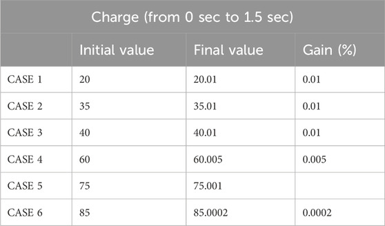
Table 3. Specifications of the gain SoC value for phase charge with PID neuronal network.
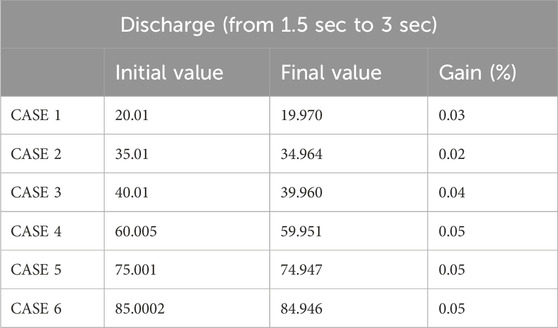
Table 4. Specifications of the gain SoC value for phase discharge with PID neuronal network.
Three sets of MOSFET in parallel enable a more effective distribution of current between phases in a three-phase interleaved DC-DC converter. The system’s voltage dips and conduction losses are decreased by this balanced current distribution. The three-phase converter can supply a larger current with a more consistent output voltage when charging the battery. Higher voltage at the battery terminal is produced by this capacity to supply more current, which enables quicker and more effective charging. In a similar vein, the three-phase converter can sustain a higher output voltage during battery drain while still supplying the required current for charging. As a result, the battery can hold onto more energy while still producing an output voltage that is steady. The two-phase converter, on the other hand, might have a less effective current distribution, which could result in higher conduction losses and a larger voltage drop. As a result, the battery voltage is marginally lower than with the three-phase converter. It is significant to remember that there are additional elements, including component design, switching losses, conversion losses, etc., that can also affect the output voltage. Therefore, it is crucial to consider these parameters while comparing two battery voltage control topologies in the three-phase converter structure and analyzing the results. Figure 13 presents the outcomes of the simulation. As seen in Figures 13A–C, PID control in conjunction with neural networks to control battery voltage offers an inventive method that delivers a high voltage that gives emphasis to initial low SoC values in the application of interlaced converters. As seen in Figures 13D–F, the voltage levels are nearly comparable for the other SoC value scenarios. Traditionally, the PID controller has been utilized to modify the converter outputs to maintain the ideal battery voltage. Nevertheless, the system can learn and adapt to intricate models of battery and charge changes by integrating neural networks, increasing control precision and efficiency. With the ability to adjust to changes in the interlaced converter’s working environment and dynamic load variations, this hybrid approach provides a more resilient and flexible solution. This method advances battery voltage management in interleaved converter applications significantly by fusing the advantages of classical PID control with the learning capacity of neural networks.
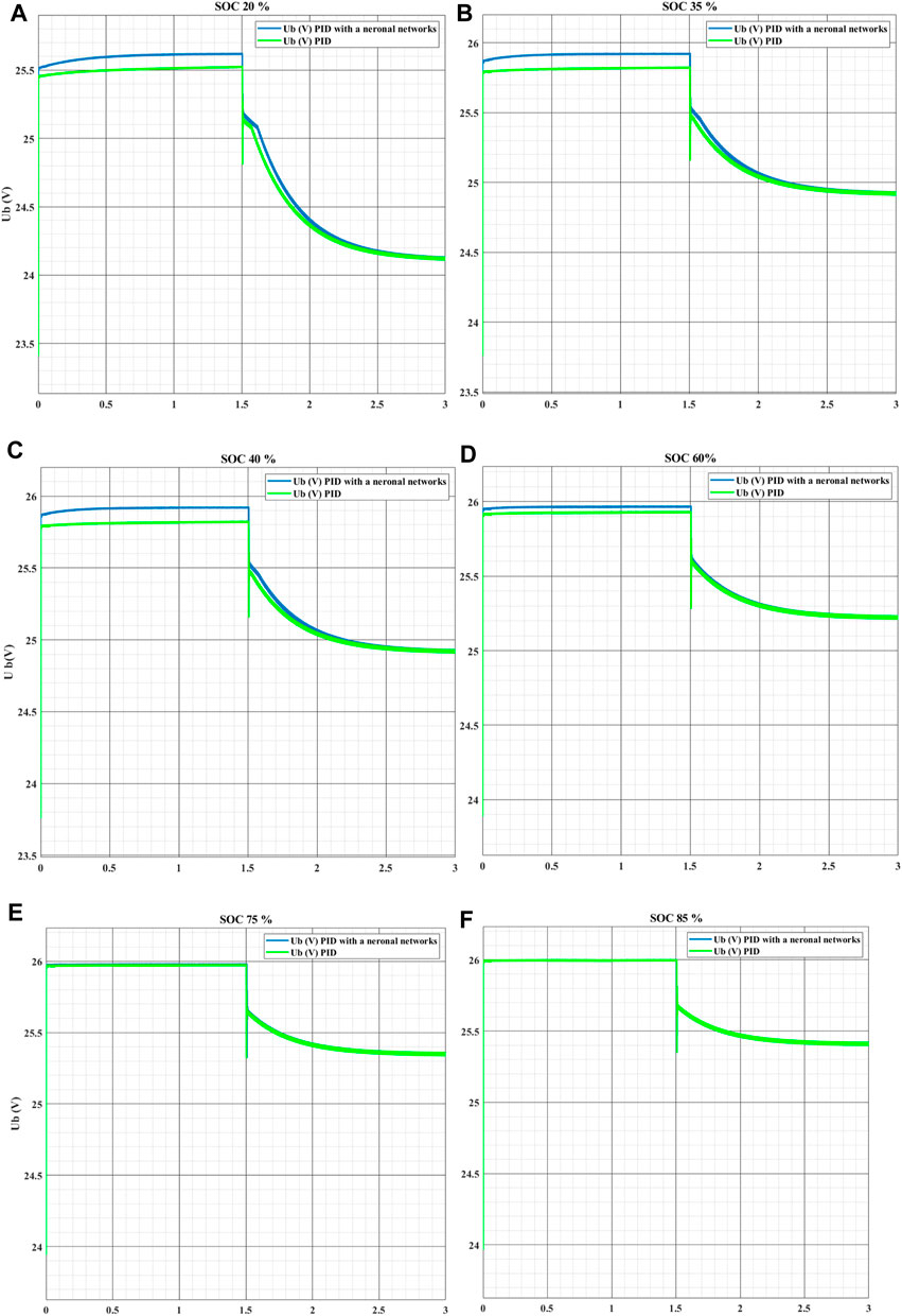
Figure 13. Battery voltage for three phases converters: (A) battery voltage for SoC 20%; (B) battery voltage for SoC 35%; (C) battery voltage for SoC 40%; (D) battery voltage for SoC 60%; (E) battery voltage for SoC 75% and (F) 85%.
An efficient option for applications needing a large output capacity and stability is the interlaced converter. Systems for transmitting energy and industrial applications are typical examples. This study suggests a unique modulation applied to a DC-converter topology in order to achieve improved efficiency and an outstanding distribution of the current between the switches. Two-way interlaced DC with two parallel switches in each phase and a battery acting as an energy storage component. The converter’s analytical explanation is finished. The converter’s analytical explanation is finished. When connecting a battery to a DC bus, the converter works wonderfully. It is clear that the particular application requirements and operating conditions influence the selection of a three-phase parallel MOSFET converter. When there is a large variation in the SoC boot value, there are a few critical considerations to take into account. With fewer parts and a more compact design, the converter including MOSFET in parallel provides a more straightforward and cost-effective solution. When SoC variations stay within a reasonably small range, it may be recommended. However, under severe load and discharge conditions, it might have limitations on output current and energy efficiency. On the other hand, in situations when there are notable changes in SoC, the converter utilizing a three-phase parallel MOSFET offers notable benefits. It provides improved output current stability, less switching losses, and improved power distribution. For energy storage systems that need to be highly reliable and efficient under a range of load and discharge situations, this makes it a better alternative.
In conclusion, because of its simplicity and lower cost, the parallel MOSFET converter might be a suitable choice for SoC boot values that vary more narrowly. On the other hand, the three-phase parallel MOSFET converter performs better in terms of output current stability, energy efficiency, and power distribution when SoC changes are substantial. A careful examination of the unique application requirements and operational limitations must form the basis of the ultimate decision. By employing synchronous MOSFET switching, a three-phase DC-DC converter with parallel MOSFETs transforms an input DC voltage into an output DC voltage. Better load distribution, increased efficiency, and more accurate output voltage regulation are made possible by this arrangement. According to this study, voltage regulation loops (PID with neural networks) can be installed on three-phase DC-DC converters to keep the output voltage constant in the face of changes in the load and input voltage.
Because of their affordability and ease of use, they may be a suitable choice. On the other hand, the three-phase converter performs better in terms of power distribution, energy efficiency, and output current stability in scenarios where SoC changes are substantial. A careful examination of the unique application requirements and operational limitations must form the basis of the ultimate decision. For a number of reasons, the combination of PID control with neural network in interlaced converters is crucial. Firstly, PID control provides a tried-and-true, effective way to control dynamic systems like voltage converters. Its straightforward design and movable settings provide accurate real-time battery voltage regulation, which is necessary to guarantee peak performance and extended battery life.
However, the incorporation of neural networks gives the control system an additional layer of flexibility and intelligence. The behavior of the battery and converter can be represented by complicated, non-linear models using neural networks, which enables control to be optimized in erratic and changing circumstances. By doing this, the system becomes more resilient to changes in load, the environment, and battery deterioration over time. PID control with neural networks, which combines these two methods, provides a comprehensive solution that combines the accuracy and adaptability of neural networks with the dependability and simplicity of PID. This makes interleaved converters more capable, more energy-efficient, and capable of intelligently managing battery voltage. It is essential for a variety of applications, including renewable energy storage systems and electric cars.
In the future, numerous lines of research can be pursued to improve and widen the conclusions reached. First, the PID with neural network controller should be tested with various battery kinds and three-phase converter technologies to ensure its durability and flexibility. Second, the use of machine learning techniques could allow for the dynamic optimization of PID with neural network settings in real time, based on load fluctuations and operational conditions. Third, it would be useful to investigate the effect of external disturbances such as temperature changes and electromagnetic interference on system performance. Finally, the development of a physical prototype and the execution of actual tests in real-world situations would provide a practical validation of the simulation results, allowing us to quantify the PID with neural network's performance in a concrete context and identify any necessary improvements. These research views will help to improve the reliability and efficiency of PID with neural network -based control systems in a variety of industrial applications.
The original contributions presented in the study are included in the article/Supplementary Material, further inquiries can be directed to the corresponding author.
HG: Funding acquisition, Methodology, Project administration, Software, Writing–original draft, Writing–review and editing. FA: Investigation, Resources, Software, Supervision, Project administration, Writing–original draft, Writing–review and editing. HK: Methodology, Project administration, Validation, Writing–original draft, Writing–review and editing. CE-B: Data curation, Resources, Software, Visualization, Writing–original draft, Writing–review and editing. YS: Software, Validation, Visualization, Writing–review and editing. MA: Software, Validation, Visualization, Writing–review and editing.
The author(s) declare financial support was received for the research, authorship, and/or publication of this article. This work was supported in part by the Deanship of Scientific Research, Northern Border University, Arar, Saudi Arabia, under Project NBU-FFR-2024-2484-6.
The authors declare that the research was conducted in the absence of any commercial or financial relationships that could be construed as a potential conflict of interest.
All claims expressed in this article are solely those of the authors and do not necessarily represent those of their affiliated organizations, or those of the publisher, the editors and the reviewers. Any product that may be evaluated in this article, or claim that may be made by its manufacturer, is not guaranteed or endorsed by the publisher.
Bai, X., Xu, M., Li, Q., and Yu, L. (2022). Trajectory-battery integrated design and its application to orbital maneuvers with electric pump-fed engines. Adv. Space Res. 70 (3), 825–841. doi:10.1016/j.asr.2022.05.014
Chen, J., Xu, J., Zhang, Y., Zhao, J., Hou, J., and Wang, Y. (2024). Geometrical state-plane-based synchronous rectification scheme for LLC converter in EVs. IEEE Trans. Transp. Electrification, 1. doi:10.1109/TTE.2024.3383208
Deng, Z., Jin, Y., Gao, W., and Wang, B. (2023). A closed-loop directional dynamics control with LQR active trailer steering for articulated heavy vehicle. Proc. Institution Mech. Eng. Part D J. Automob. Eng. 237 (12), 2741–2758. doi:10.1177/09544070221121859
Duan, J., Wang, S., Xu, Y., Fan, S., Zhao, K., and Sun, L. (2023). Variable multiple interleaved Bi-directional DC/DC converter with current ripple optimization. Appl. Sci. 13 (3), 1744. doi:10.3390/app13031744
Fei, M., Zhang, Z., Zhao, W., Zhang, P., and Xing, Z. (2024). Optimal power distribution control in modular power architecture using hydraulic free piston engines. Appl. Energy 358, 122540. doi:10.1016/j.apenergy.2023.122540
Feng, Y., Chen, J., and Luo, J. (2024). Life cycle cost analysis of power generation from underground coal gasification with carbon capture and storage (CCS) to measure the economic feasibility. Resour. Policy 92, 104996. doi:10.1016/j.resourpol.2024.104996
Fu, Z., Hu, M., Guo, Q., Jiang, Z., Guo, D., and Liao, Z. (2023). Research on anti-rollover warning control of heavy dump truck lifting based on sliding mode-robust control. Proc. Institution Mech. Eng. Part D J. Automob. Eng. 238, 1330–1351. doi:10.1177/09544070231160901
Gao, Y., Doppelbauer, M., Ou, J., and Qu, R. (2022). Design of a double-side flux modulation permanent magnet machine for servo application. IEEE J. Emerg. Sel. Top. Power Electron 10 (2), 1671–1682. doi:10.1109/JESTPE.2021.3105557
Grisales-Noreña, L. F., Montoya, O. D., and Gil-González, W. (2019). Integration of energy storage systems in AC distribution networks: optimal location, selecting, and operation approach based on genetic algorithms. J. Energy Storage 25, 100891. doi:10.1016/j.est.2019.100891
Guo, C., and Hu, J. (2023). Time base generator-based practical predefined-time stabilization of high-order systems with unknown disturbance. IEEE Trans. Circuits Syst. II Express Briefs 70 (7), 2670–2674. doi:10.1109/TCSII.2023.3242856
Li, S., Zhao, X., Liang, W., Hossain, M. T., and Zhang, Z. (2022). A fast and accurate calculation method of line breaking power flow based on taylor expansion. Front. Energy Res. 10 (Jul). doi:10.3389/fenrg.2022.943946
Luo, R., Peng, Z., Hu, J., and Ghosh, B. K. (2023). Adaptive optimal control of affine nonlinear systems via identifier–critic neural network approximation with relaxed PE conditions. Neural Netw. 167, 588–600. doi:10.1016/j.neunet.2023.08.044
Mayer, R., El Kattel, M. B., and Oliveira, S. V. G. (2021). Multiphase interleaved bidirectional DC/DC converter with coupled inductor for electrified-vehicle applications. IEEE Trans. Power Electron 36 (3), 2533–2547. doi:10.1109/TPEL.2020.3015390
Mohammadzadeh, A., Taghavifar, H., Zhang, C., Alattas, K. A., Liu, J., and Vu, M. T. (2024). A non-linear fractional-order type-3 fuzzy control for enhanced path-tracking performance of autonomous cars. IET Control Theory & Appl. 18 (1), 40–54. doi:10.1049/cth2.12538
Rasouli Heikalabad, S. (2024). Reversible priority encoder in quantum-dot cellular automata. Inorg. Chem. Commun. 164, 112401. doi:10.1016/j.inoche.2024.112401
Shen, Y., Liu, D., Liang, W., and Zhang, X. (2023). Current reconstruction of three-phase voltage source inverters considering current ripple. IEEE Trans. Transp. Electrification 9 (1), 1416–1427. doi:10.1109/TTE.2022.3199431
Song, F., Liu, Y., Shen, D., Li, L., and Tan, J. (2022c). Learning control for motion coordination in wafer scanners: toward gain adaptation. IEEE Trans. Industrial Electron. 69 (12), 13428–13438. doi:10.1109/TIE.2022.3142428
Song, J., Mingotti, A., Zhang, J., Peretto, L., and Wen, H. (2022a). Fast iterative-interpolated DFT phasor estimator considering out-of-band interference. IEEE Trans. Instrum. Meas. 71, 1–14. doi:10.1109/TIM.2022.3203459
Song, J., Mingotti, A., Zhang, J., Peretto, L., and Wen, H. (2022b). Accurate damping factor and frequency estimation for damped real-valued sinusoidal signals. IEEE Trans. Instrum. Meas. 71, 1–4. doi:10.1109/TIM.2022.3220300
Sun, Y., Peng, Z., Hu, J., and Ghosh, B. K. (2024). Event-triggered critic learning impedance control of lower limb exoskeleton robots in interactive environments. Neurocomputing 564, 126963. doi:10.1016/j.neucom.2023.126963
Syah, M. N., Firmansyah, E., and Utomo, D. R. (2022). “Interleaved bidirectional DC-DC converter operation strategies and problem challenges: an overview,” in 2022 IEEE International Conference in Power Engineering Application (ICPEA), Shah Alam, Malaysia, 07-08 March 2022 (IEEE), 1–6.
Wang, Y., Xu, J., Qiao, L., Zhang, Y., and Bai, J. (2023). Improved amplification factor transport transition model for transonic boundary layers. AIAA J. 61 (9), 3866–3882. doi:10.2514/1.J062341
Xue, F., Yu, R., and Huang, A. Q. (2017). A 98.3% efficient GaN isolated bidirectional DC–DC converter for DC microgrid energy storage system applications. IEEE Trans. Industrial Electron. 64 (11), 9094–9103. doi:10.1109/TIE.2017.2686307
Zhang, H., Wu, H., Jin, H., and Li, H. (2023b). High-dynamic and low-cost sensorless control method of high-speed brushless DC motor. IEEE Trans. Ind. Inf. 19 (4), 5576–5584. doi:10.1109/TII.2022.3196358
Zhang, X., Gong, L., Zhao, X., Li, R., Yang, L., and Wang, B. (2023a). Voltage and frequency stabilization control strategy of virtual synchronous generator based on small signal model. Energy Rep. 9, 583–590. doi:10.1016/j.egyr.2023.03.071
Zhang, X., Lu, Z., Yuan, X., Wang, Y., and Shen, X. (2021). L2-Gain adaptive robust control for hybrid energy storage system in electric vehicles. IEEE Trans. Power Electron 36 (6), 7319–7332. doi:10.1109/TPEL.2020.3041653
Zhou, X., Cai, Y., and Li, X. (2024). Process arrangement and multi-aspect study of a novel environmentally-friendly multigeneration plant relying on a geothermal-based plant combined with the goswami cycle booted by kalina and desalination cycles. Energy 299, 131381. doi:10.1016/j.energy.2024.131381
Zhu, C., Wang, M., Guo, M., Deng, J., Du, Q., Wei, W., et al. (2024b). Optimizing solar-driven multi-generation systems: a cascade heat recovery approach for power, cooling, and freshwater production. Appl. Therm. Eng. 240, 122214. doi:10.1016/j.applthermaleng.2023.122214
Keywords: interleaved bidirectional DC-DC converter, parallel-connected MOSFET, buck-boost DC-DC converter, battery storage, SOC
Citation: Gaied H, Aymen F, Kraiem H, El-Bayeh CZ, Said Y and Almalki MM (2024) Three phase bidirectional DC-DC converters based neural network controller for renewable energy sources. Front. Energy Res. 12:1391310. doi: 10.3389/fenrg.2024.1391310
Received: 25 February 2024; Accepted: 14 June 2024;
Published: 23 August 2024.
Edited by:
Hugo Morais, University of Lisbon, PortugalReviewed by:
Sheeraz Iqbal, University of Azad Jammu and Kashmir, PakistanCopyright © 2024 Gaied, Aymen, Kraiem, El-Bayeh, Said and Almalki. This is an open-access article distributed under the terms of the Creative Commons Attribution License (CC BY). The use, distribution or reproduction in other forums is permitted, provided the original author(s) and the copyright owner(s) are credited and that the original publication in this journal is cited, in accordance with accepted academic practice. No use, distribution or reproduction is permitted which does not comply with these terms.
*Correspondence: Habib Kraiem, YWxoYWJlZWIua2FyZWVtQG5idS5lZHUuc2E=
Disclaimer: All claims expressed in this article are solely those of the authors and do not necessarily represent those of their affiliated organizations, or those of the publisher, the editors and the reviewers. Any product that may be evaluated in this article or claim that may be made by its manufacturer is not guaranteed or endorsed by the publisher.
Research integrity at Frontiers
Learn more about the work of our research integrity team to safeguard the quality of each article we publish.