 Chuanbao Yi1,2Zequan Zhang3Haiyang Dong3
 Yonggang Lu3Shuangquan Xu1Xiji Li1Chuanzhen Sun1Shuaishuai Zhang1
 Zhengwei Wang3*
- 1State Grid Xinyuan Shandong Weifang Pumped Storage Co., Ltd., Weifang, Shandong, China
- 2School of Control and Computer Engineering, North China Electric Power University, Beijing, China
- 3State Key Laboratory of Hydroscience and Engineering, Tsinghua University, Beijing, China
The vibration issue of pumped storage power station unit will directly affect the safe and stable operation of the unit, and the pressure pulsation in the vaneless region is an important index to evaluate the stability of the unit. In order to study the pressure fluctuation characteristics of the vaneless region of the pump-turbine in the turbine mode, the unsteady numerical simulation of the maximum head condition and the rated head condition is carried out in this research. The amplitude-frequency characteristics of the pressure fluctuation in the vaneless region under different head and the influence of the internal flow characteristics on the pressure fluctuation are analyzed. The results show that the non-uniform pressure field is formed in the vaneless region due to the rotor-stator interaction (RSI) between the long and short blades of the runner and the guide vanes. The main frequency of pressure pulsation in the vaneless region is 5fn, which is half of the blade passing frequency (BPF), that is, the blade combination passing frequency. The main sub-frequencies are 10fn, 15fn, and 20fn. In addition, the amplitude of pressure pulsation at each frequency under the rated head condition is higher than that under the maximum head condition. In a rotating cycle, the discrete blade vortex in the runner flow channel gradually accumulates and evolves into the big scale vortex on the side of the pressure surface of the short blade, which aggravates the pressure fluctuation in the vaneless region. The intensity of the vortex under the rated head condition is larger, which reasonably explains the reason why the pressure fluctuation amplitude under the rated head condition is larger.
1 Introduction
The continuous depletion of fossil energy sources and the deterioration of the environment have become a major problem restricting energy development, and the development of renewable energy sources has become an unstoppable trend to solve this problem. As a clean energy source, hydropower plays the roles of peak and trough regulation in hydropower system by virtue of its strong load capability and fast response. Pumped storage, as a mature large-scale energy storage method, is a flexible regulation battery in the power system (Kulpa et al., 2024). Vibration and noise problems may occur during the operation of the pump-turbine, mainly due to the hydraulic imbalance caused by the internal flow of the unit, such as rotor-stator interaction (RSI) (Zhang et al., 2021; Hu H. et al., 2023). The resulting pressure pulsation characteristics are important indicators for evaluating the stability of the unit. The pressure pulsation characteristics of the pump-turbine have become the focus of research by scholars at home and abroad in recent years.
Due to the RSI between the guide vanes and the runner, which makes a large pressure pulsation in the vaneless region, the unit may vibrate, thus affecting the safe and stable operation of the whole unit, so it is necessary to study the flow mechanism and pulsation characteristics in the vaneless region. Scholars have studied the pressure pulsation characteristics of pump-turbine under different working conditions, and found that the main frequency of pressure pulsation in the vaneless region is basically the blade passing frequency (BPF) and its frequency doubling, and the main frequency is also half of the BPF (Li et al., 2016; Zhang et al., 2017; Xie et al., 2022; Hu J. et al., 2023). The source and formation mechanism of pressure pulsation in the vaneless region are also studied. Hu et al. (2021) proposed the expression of the relationship between the frequency pressure amplitude and the speed factor of the blade in the vaneless region, and quantitatively compared the RSI intensity of different pump-turbines. Trivedi et al. (2018) found that the pressure amplitude of the vaneless region and the runner is about 10%–20% of the hydraulic energy, and the high amplitude fluctuation occurs at the pulsation frequency caused by the RSI. Su et al. (2021) studied the pressure pulsation characteristics of the pump-turbine during the runaway transition process, and found that the low-frequency pulsation components caused by the flow rate change are common in the flow channel, and the frequency amplitude caused by the RSI is the largest at the runner. Fan et al. (2022) found that the use of long and short blades in the runner will significantly reduce the amplitude of pressure pulsation and effectively alleviate the vibration problems in the operation of the unit. Zheng et al. (2023) found that the pressure fluctuation in the vaneless region is caused by the unstable flow in the vaneless region and the low-frequency vortex rope in the draft tube. Rode and Kumar (2023) found that RSI, runaway and load rejection can aggravate the pressure pulsation in the vaneless region. Xu et al. (2020) proposed that the high-amplitude pressure pulsation in the vaneless region is mainly due to the mechanism of the vortex on the pressure surface of the runner blade.
The pressure fluctuation in the vaneless region is affected by many factors. Studies have shown that factors such as unstable flow and rotating stall can affect the pressure fluctuation in the vaneless region. Li et al. (2015) used the dynamic mesh technique to simulate the dynamic process of pressure pulsation in the vaneless region, and found that the rotation of the guide vane would greatly affect the pressure pulsation in the vaneless region. Xia et al. (2017) studied the influence of flow evolution in the S-region of the pump-turbine on the pressure fluctuation. It was found that the reverse flow vortex structure (RFVS) distributed on the hub side of the runner enhanced the local RSI. In addition, the rotating stall makes the low-frequency components of the pressure fluctuation unevenly distributed in the vaneless region along the circumferential direction. Deng et al. (2022) studied the influence of local flow in the vaneless region on the characteristics of pressure pulsation, and found that the instability factors in the vaneless region mainly include RSI and eddy motion, and the eddy motion in the vaneless region also enhances the pressure pulsation caused by RSI. Wang et al. (2021) used PIV technology to find that unstable flow in the vaneless region causes high-amplitude pressure pulsations. Zhao et al. (2023) found that the pressure in the vaneless region during load rejection is mainly affected by the rotational speed, and the peak-to-peak value of pressure pulsation is affected by the RSI and rotating stall. Huang et al. (2020) found that the pressure pulsation in the vaneless region with different guide vane heights was significantly different, and the amplitude of the RSI frequency from the vaneless region to the guide vane outlet was continuously attenuated.
Therefore, the pressure fluctuation in the vaneless region is an important index to evaluate the stable operation of the unit. Therefore, this research analyzes the pressure fluctuation characteristics of the vaneless region under the rated head working condition and the maximum head working condition of the pump-turbine under the 100% load of the turbine mode, and obtains the main frequency and peak-to-peak value of the pressure fluctuation in the vaneless region, which provides a theoretical reference for improving the operational stability of the unit.
2 Calculation model and numerical simulation
2.1 Research object
The research object of this research is the vertical shaft single-stage mixed-flow reversible pump-turbine of a certain pumped storage power station. The runner adopts a special structure with five long blades and five short blades staggered arrangement. The full flow channel pump-turbine model is shown in Figure 1, mainly including spiral casing, stay vane, guide vane, runner, draft tube, upper crown and lower ring clearance and pressure balance pipe. The rated head of the pump-turbine is 326 m, the rated rotation speed is 333.3 rpm, and the rated output is 306 MW. The main parameters of the pump-turbine are shown in Table 1.
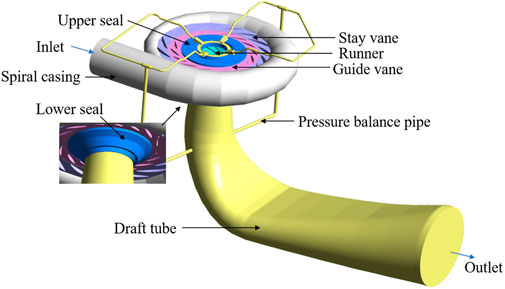
Figure 1. Calculation model of full channel fluid domain of pump-turbine.
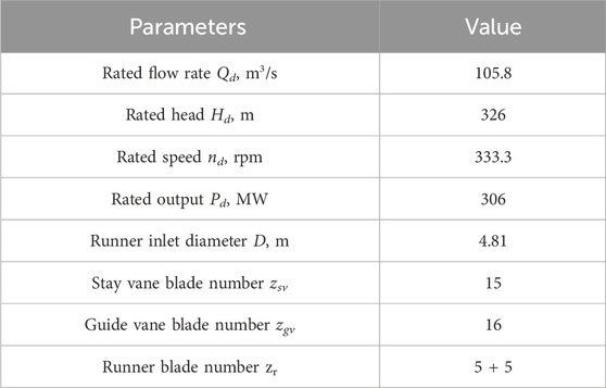
Table 1. Main parameters of pump-turbine.
2.2 Governing equation and turbulence model
Numerical simulation is a method that the governing equations of the flow field are discretized to the grid nodes by computational mathematics to obtain the discrete numerical solution. The flow of fluid follows the law of conservation of mass, the law of conservation of momentum and the law of conservation of energy. The equations are expressed as follows:
The continuity equation is shown as Equation 1 (Gu et al., 2024):
where
The momentum equation is shown as Equation 2:
where ρ is fluid density, t is time coordinate,
In this research, the Shear Stress Transport (SST) k-ω turbulence model is selected for numerical simulation. The turbulence viscosity of the model takes into account the propagation of shear stress, and has a large scope of application and high calculation accuracy. The turbulence model equations are as Equations 3, 4:
where k is turbulence kinetic energy, xj is spatial coordinate, Pk is production term of k, μ is dynamic viscosity, ω is the specific dissipation rate, μt is turbulence kinematic viscosity, Cω is the coefficient of the production term, F1 is blending function, σω, β and σω2 are closure parameters.
2.3 Grid division and CFD setup
In this research, ICEM CFD grid division software is used to mesh the whole flow channel fluid domain of the pump-turbine. The stay vane, the guide vane, the draft tube and the upper crown and lower ring clearance adopt the form of hexahedral grid. The volute, the runner and the pressure balance pipe adopt the tetrahedral grid with eminent adaptability. In order to eliminate the influence of the elements of grids on the numerical simulation result, as shown in Figure 2, five sets of grid division schemes are set up to verify the grid independence. It can be seen that with the increase of the elements of grids, the increase of the flow rate is less significant. Considering the calculation accuracy and efficiency, the third set of grid schemes is selected for numerical simulation, and the total number of grids is 8.5 million. The specific division results are as follows: the elements of grids of spiral casing, stay vane, guide vane, runner, draft tube, pressure balance pipe, upper seal and lower seal are 1.64 million, 0.4 million, 0.9 million, 3.7 million, 1.2 million, 0.18 million, 0.22 million, and 0.26 million respectively. The grid division of the fluid domain of the pump-turbine is shown in Figure 3.
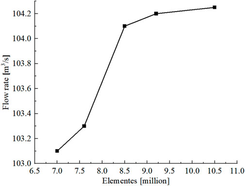
Figure 2. Verification of grid independence.
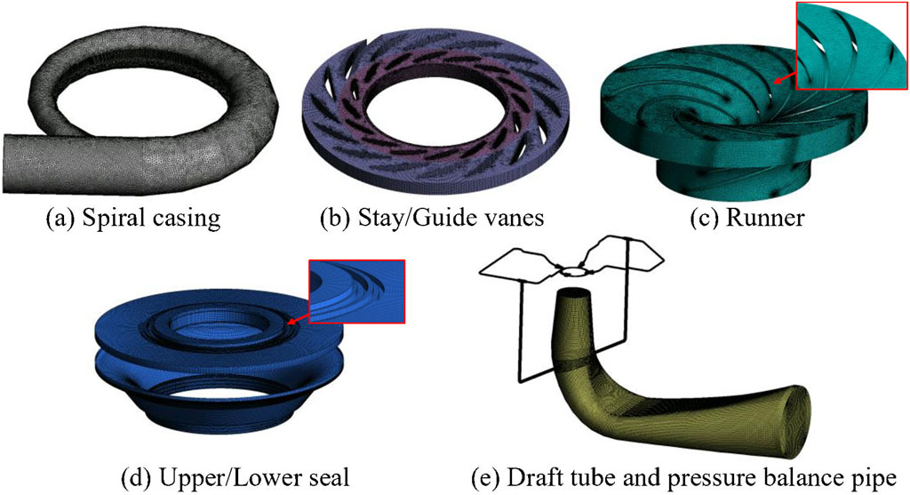
Figure 3. Grid division of different components of pump-turbine.
In this research, the inlet boundary condition is set to Total Pressure, and the outlet boundary condition is set to Static Pressure (Zhang et al., 2024). The reference pressure is set to 1 atm. The wall condition adopts the No Slip Wall, and the standard wall function is used in the near-wall region. The convergence residual accuracy is set to 10−4. In the steady calculation, the dynamic and static interface between the guide vane and the runner is set to Frozen Rotor, and in the unsteady calculation, the dynamic and static interface is set to Transient Rotor Stator. The unsteady calculation takes the steady calculation result as the initial value, takes the time of the runner rotating 2° as a calculation step, and the total time is 1.440144 s corresponding to eight rotation cycles.
3 Results and analysis
In this research, numerical simulation was carried out at the rated rotation speed of 333.3 rpm to study the pressure pulsation characteristics and internal flow characteristics of the vaneless region under the maximum and rated head conditions in the turbine mode of the pump-turbine. The numerical calculation results are shown in Figure 4. From the results of numerical calculation, the flow rate, output and efficiency of the rated head working condition are slightly higher than those of the maximum head working condition. The two calculation working conditions are simulated under 100% output (306 MW). It can be seen that the simulation value of the rated head working condition is closer to the theoretical value.
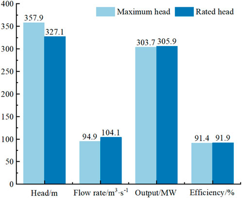
Figure 4. The main calculation results of two working conditions.
3.1 Analysis of pressure pulsation characteristics in the vaneless region
The vibration of pumped storage unit is a common engineering phenomenon, which will affect the safe and stable operation of the unit and the economic benefit of the power station, especially the vibration of the unit and the plant caused by pressure pulsation in the vaneless region. The pressure pulsation in the vaneless region is the main excitation source that causes the vibration of the pumped storage unit, and it is also the pressure pulsation with the largest amplitude of the full flow channel of the pump-turbine unit, which is mainly manifested as the rotor-stator interaction between the fixed and rotating parts.
The pressure peak-to-peak value is used to characterize the intensity of pressure pulsation. Figure 5 shows the distribution of pressure pulsation peak-to-peak value (ΔH, m) in the middle flow surface of the guide vane channel. It can be seen that the pressure pulsation peak-to-peak value in the vaneless region is significantly higher than that in other regions, and the peak-to-peak value in the vaneless region under the rated head condition is slightly higher than that under the maximum head condition. In addition, due to the asymmetry of the spiral casing and other factors, there are some differences in the peak and peak values of pressure pulsation at different positions in the vaneless region. The larger peak and peak values of pressure pulsation appear near the trailing edge of the guide vane. Therefore, it is of great significance to study the amplitude-frequency characteristics of pressure pulsation in the vaneless region. The calculation formula of peak and peak value of pressure pulsation is as Equation 5:
where Pmax is the maximum pressure in a rotation period, Pa. Pmin is the minimum pressure in a rotation period, Pa. ρ is the density of fluid, kg/m3. g is the acceleration of gravity, m/s2.
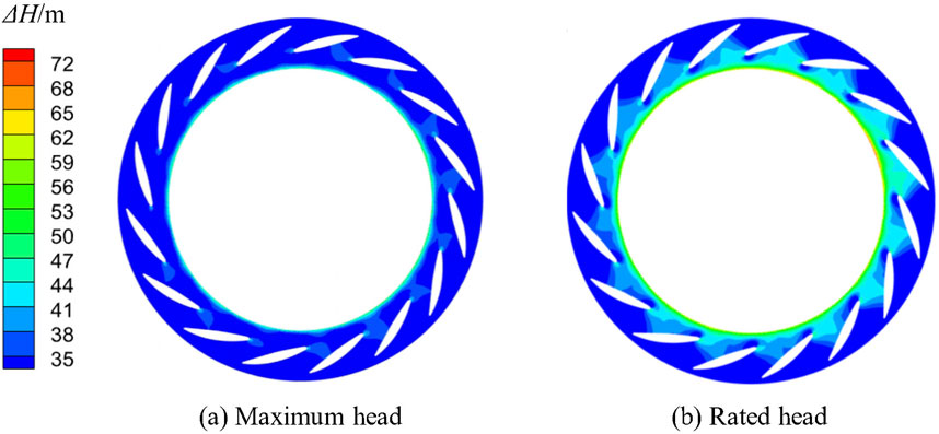
Figure 5. Pressure peak-to-peak value distribution in vaneless region.
In order to further study the pressure pulsation characteristics at different positions in the vaneless region, eight pressure monitoring points VR01∼VR08 are set up in the vaneless region of the middle flow surface of the guide vane, and the distribution is as shown in the Figure 6. In order to better characterize the degree of pressure fluctuation in the vaneless region, the dimensionless coefficient Cp of pressure fluctuation is introduced to explore the pressure fluctuation of the monitoring points in a rotation period. The equation is shown as Equation 6:
where P is the pressure value at different times in a period, Pa.
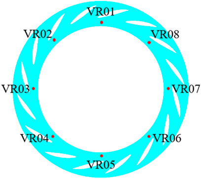
Figure 6. Distribution of pressure monitoring points in the vaneless region.
The time domain distribution of the pressure monitoring points in the vaneless region under the maximum head condition and the rated head condition is shown in Figure 7. It can be seen that the pressure in the vaneless region shows five obvious peaks and five troughs in a rotation period, and the pressure fluctuation trend of each monitoring point is basically the same. During this period, the runner rotates by 72°, and the periodicity comes from the rotor-stator interaction (RSI) between the guide vane and the runner blade, and the pressure fluctuation peak value of the rated head condition is slightly higher than that of the maximum head condition.

Figure 7. Time domain distribution of the pressure monitoring points in the vaneless region.
In order to further study the amplitude-frequency characteristics of pressure pulsation in the vaneless region, the time domain signal of pressure pulsation is transformed into frequency domain signal by Fast Fourier Transform (FFT), and the influence of different frequency components on pressure pulsation is obtained. The Figure 8 shows the spectrum distribution of pressure pulsation under maximum head condition and rated head condition respectively. It can be seen that the frequency distribution of pressure pulsation at different positions in the vaneless region is basically the same. The main frequency of pressure pulsation under both conditions is 5fn, half of the blade passing frequency (BPF) of 10fn, that is, the passing frequency of blade combination. The main sub-frequencies are 10fn, 15fn, and 20fn, all of which are integer multiples of the passing frequency of blade combination of the runner. The Figure 9 shows the amplitude distribution corresponding to the main frequencies of pressure pulsation in the vaneless region under maximum head condition and rated head condition. It can be seen that each frequency amplitude under rated head condition is higher than that under maximum head condition, and the pulsation amplitude difference between rated head condition and maximum head condition is the largest when the pulsation main frequency is 0.5 BEP. The distribution uniformity of pressure pulsation in the vaneless region is worse in the circumferential direction under the maximum head condition, and the amplitude of each frequency varies greatly at different positions, while the difference of each frequency amplitude at different positions in the vaneless region under the rated head condition is small, which shows a nearly circular distribution in the radar map.
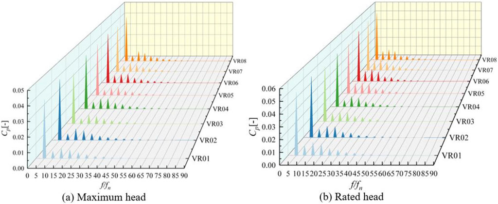
Figure 8. Time domain diagram of the pressure monitoring points in the vaneless region.
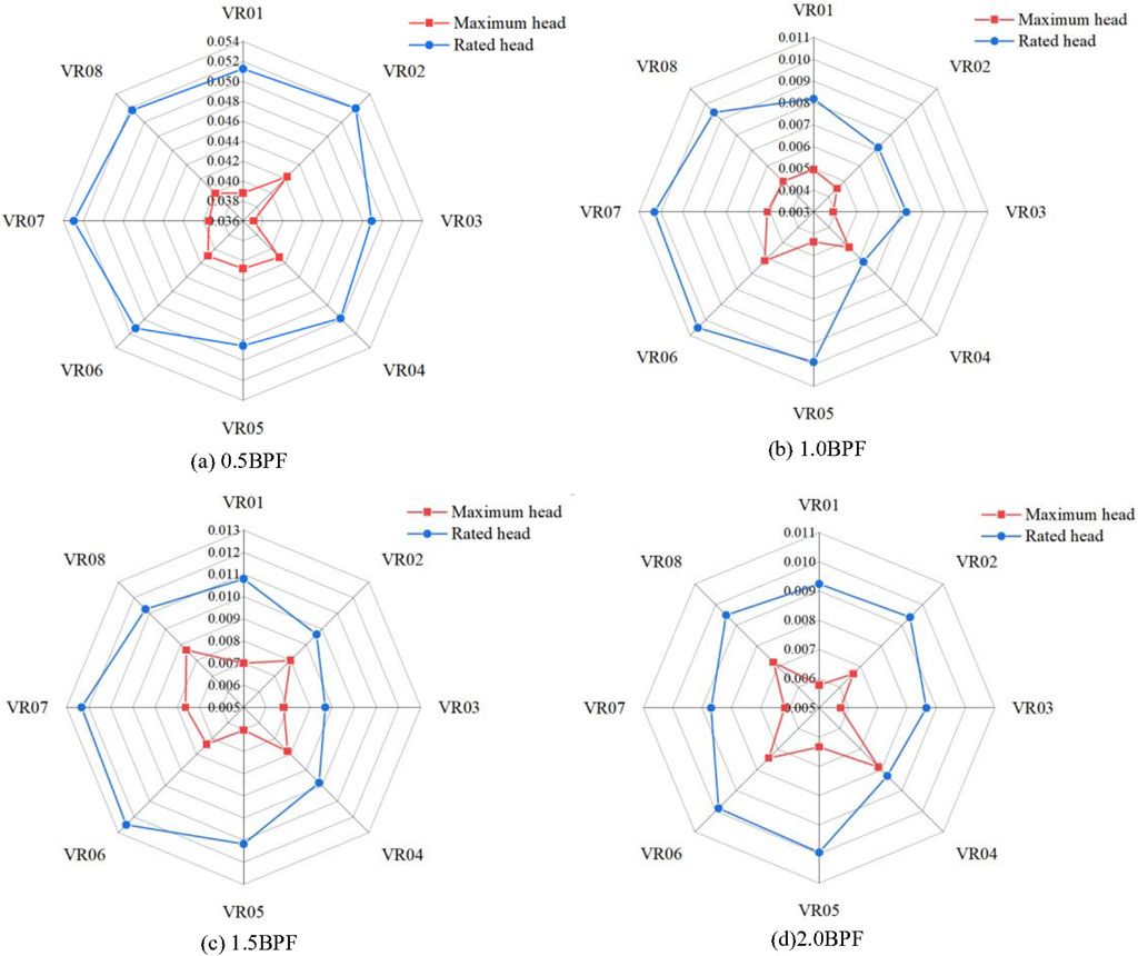
Figure 9. Amplitude of the main frequencies of pressure pulsation in the vaneless region.
3.2 Analysis of internal flow characteristics of pump-turbine
The pressure fluctuation in the vaneless region mainly comes from the disturbance of the long and short blades of the runner to the fluid. The uneven pressure distribution in the runner leads to the alternating high and low pressure passing through the vaneless region, thus forming the pressure fluctuation. Therefore, the pressure fluctuation characteristics of the vaneless region of the pump-turbine are closely related to the internal flow.
In order to further study the formation mechanism of pressure pulsation in the vaneless region, the pressure distribution of the monitoring point VR01 at the maximum head condition in the five moments of the 1/5 period is studied. Each moment is correspondence with the marking time of Figure 7A. Figure 10 is the pressure cloud diagram of the middle flow surface of the guide vane at different times. It can be seen that there will be a low pressure area in the vaneless region facing the short blade of the runner, so the pressure of the point VR01 is affected by this and shows obvious periodic changes. When t1 = 0T, the pressure at VR01 reaches the peak, which corresponds to the high pressure area in the pressure cloud diagram. At this time, the distance between the short blade and the point VR01 is the farthest. When t2 = 0.072T, the short blade is constantly approaching VR01, resulting in a pressure valley at the monitoring point. As the runner continues to rotate, a small peak and a small trough appear at t3 = 0.094T and t4 = 0.122T, respectively. When t5 = 0.2T, the runner rotates 72°, the relative position of the runner blade and the guide vane remains unchanged, and the pressure peak appears again at point VR01. It can be seen that the rotor-stator interaction (RSI) between the runner and the guide vane forms a non-uniform pressure field in the vaneless region, and the rotor-stator interaction (RSI) in the vaneless region is more affected by the short blades of the runner.

Figure 10. Pressure distribution of different moments at the maximum head condition.
In order to study the internal flow characteristics of different blade height positions in the vaneless region, Figure 11 shows the velocity streamline distribution of the stay/guide vane and the runner on different blade height surfaces under two working conditions. It can be seen that the streamlines in the vaneless region and the runner are relatively uniform, and there is no obvious unstable flow such as vortex and backflow. The high-speed flow mainly occurs in the vaneless region between the guide vane and the runner inlet, and there is an obvious high-speed circularity flow in the vaneless region of the maximum head, which is mainly due to the obvious high-speed circularity flow in the vaneless region at the maximum head. In addition, under the maximum head condition, the incoming flow angle of the runner does not match the runner blade, and there is a more obvious flow separation phenomenon on the side of the short blade pressure surface in the middle flow surface of the runner, which blocks part of the runner channel, so there is a more obvious stall area here.
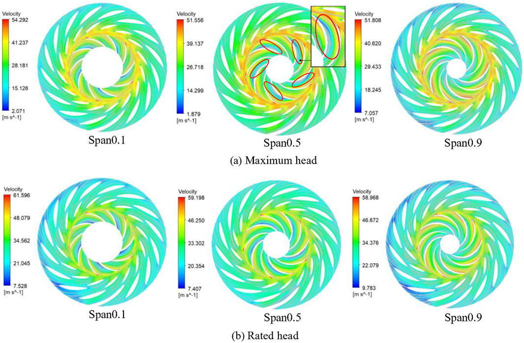
Figure 11. Velocity streamline distribution of the stay/guide vane and the runner.
Figure 12 shows the distribution of Turbulent Kinetic Energy (TKE) on the middle flow surface of the stay/guide vane and the runner. It can be seen that due to the asymmetric distribution of the spiral casing, there is a circumferential difference in the flow of the guide vane, so the TKE is not evenly distributed. The larger TKE in the guide vane area mainly occurs at casing tongue and the trailing edge of some guide vanes. The higher TKE in the runner is mainly distributed on the side of the pressure surface of the runner blade. This is because the flow on the side of the pressure surface hinders the flow of the mainstream, which makes the TKE larger and produces a larger hydraulic loss. Obviously, the TKE under the maximum head working condition is slightly higher than that under the rated head working condition, which is more consistent with the flow separation phenomenon in the runner under the maximum head working condition.
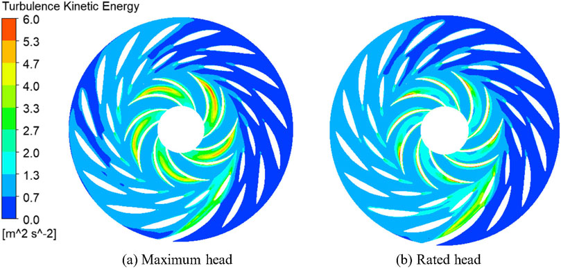
Figure 12. TKE distribution of the stay/guide vane and the runner.
Figure 13 shows the pressure distribution on the pressure surface and suction surface of the long and short blades of the runner under two working conditions. It can be seen that the pressure distribution of the runner under the maximum head condition and the rated head condition is basically the same. The pressure from the inlet to the outlet of the runner decreases gradually, and the pressure on the pressure surface is significantly higher than that on the suction surface. In addition, the pressure gradient distribution on the pressure surface is more uniform.
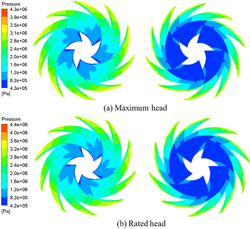
Figure 13. Pressure distribution on the pressure surface and suction surface of the runner.
3.3 Inner vortex evolution characteristics of the runner
When the pump-turbine is operating under the turbine condition, unstable flow phenomena such as flow separation and backflow will occur in the runner, thus forming common blade vortex, Karman vortex and flow separation vortex. The draft tube is prone to spiral vortex in the straight cone section, resulting in hydraulic loss of the pump-turbine, which leads to a decrease in operating efficiency. Therefore, the vortex extraction technology is used to extract the inner vortex of the runner under two working conditions, and the Q-criterion is used to identify it.
Figure 14 shows the evolution process of the inner vortex in a rotating period of the runner. It can be seen that the vortex distribution in the runner of the two working conditions is basically the same, and there is no significant difference. At 1/3 period, the runner flow channel is filled with small-scale blade vortex, which extends from the runner inlet to the runner outlet. At 2/3 period, the large-scale vortex in the runner gradually increases, mainly distributed on the side of the pressure surface of the short blade, and the scale of the blade vortex gradually increases, which still fills the whole runner channel. At 1 period, the blade vortex filled in the runner channel gradually disappears, and it gathers into a large-scale vortex at the pressure surface of the short blade near the runner inlet.
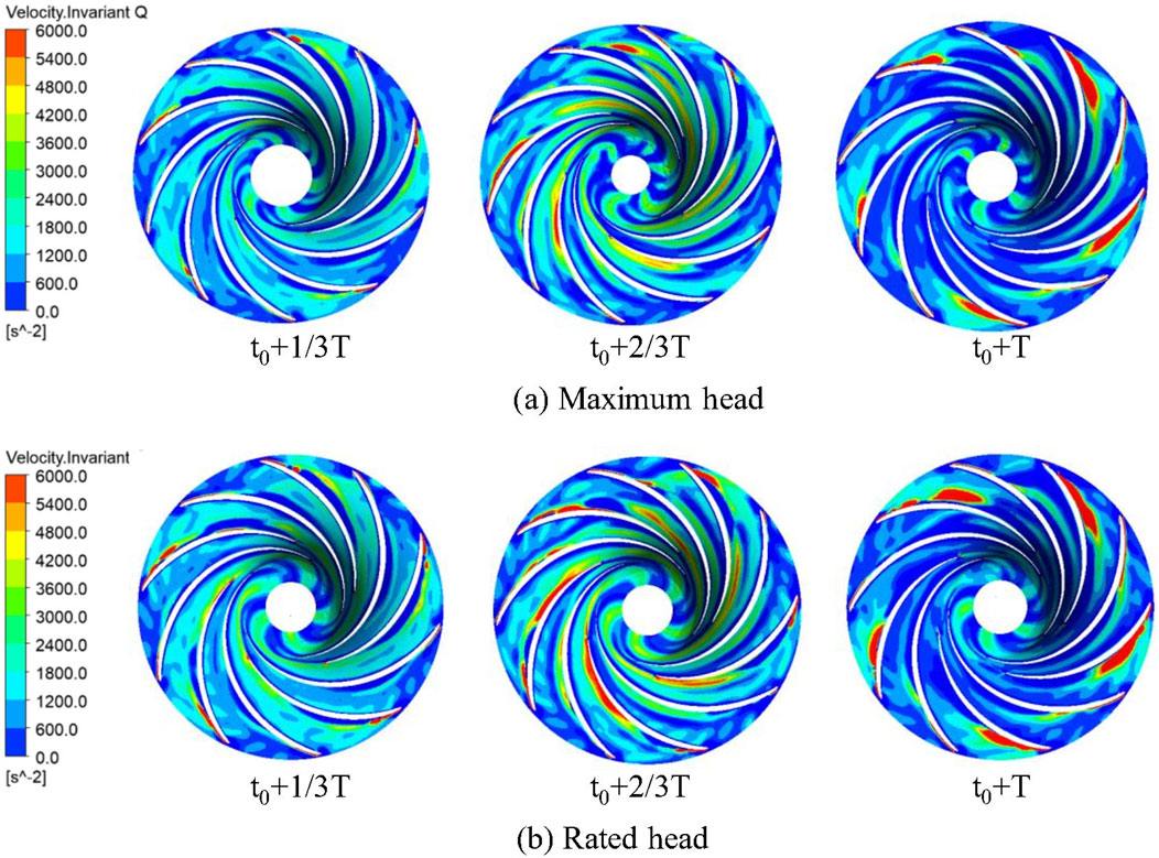
Figure 14. Inner vortex evolution of the runner in a rotating period.
It can be seen that the internal vortex of the runner gradually evolves from the blade vortex to the pressure surface big scale vortex of the leading edge of the short blade in a rotation period. The pressure of the vortex core of the vortex is low, while the pressure in the high pressure area is still high, forming a high and low pressure distribution at the inlet of the runner. Therefore, the rotation of the runner through the vaneless region will aggravate the pressure pulsation. The flow rate at the rated head condition exceeds that at the maximum head condition, leading to increased unstable flow in the runner. This enhances vortex intensity and aggravates pressure pulsations in the vaneless region, which is consistent with the amplitude characteristics of the pressure fluctuation.
4 Conclusion
In this research, the numerical simulation of the maximum head condition and the rated head condition of the pump-turbine in the turbine mode is carried out to study the amplitude-frequency characteristics and internal flow characteristics of the pressure pulsation in the vaneless region. In addition, the influence of the internal flow on the pressure pulsation in the vaneless region is also studied. This research is of great significance to the practical problems of unit vibration caused by RSI. To a certain extent, it ensures the stable operation of the unit and plays an important role in optimizing the operation of the unit. The main conclusions are as follows:
(1) According to the distribution of pressure pulsation peak-to-peak value ΔH, the vaneless region exhibits a significantly higher ΔH compared to other regions, with the larger values concentrated near the trailing edge of the guide vanes. Furthermore, under rated head working condition, the ΔH in the vaneless region is slightly higher than that under maximum head working condition.
(2) Through the analysis of pressure pulsation characteristics in the bladeless region, it is found that the main frequency of pressure pulsation in the vaneless region is half of the blade passing frequency (BPF), which is 5fn, that is, the blade combination passing frequency. The main sub-frequencies are 10fn (BPF), 15fn and 20fn, and the pulsation amplitude of the rated head condition is larger. And the uniformity of the circumferential distribution of pressure pulsation in the vaneless region under the rated head condition is better.
(3) Through the analysis of the internal flow characteristics, it is concluded that: under the influence of rotor-stator interaction (RSI), there is an obvious high-speed circularity flow in the vaneless region of the maximum head condition, and there is a more obvious flow separation phenomenon on the side of the pressure surface of the short blade of the runner, blocking part of the runner flow channel, and a stall area appears here.
(4) Through the analysis of the evolution characteristics of the inner vortex of the runner, it can be concluded that, during a rotating period, the discrete blade vortex in the runner flow channel gradually gathers into a vortex near the runner inlet on the side of the pressure surface of the short blade, and the intensity of the vortex under the rated head condition is greater, which aggravates the pressure fluctuation in the vaneless region.
Data availability statement
The original contributions presented in the study are included in the article/Supplementary Material, further inquiries can be directed to the corresponding authors.
Author contributions
CY: Conceptualization, Methodology, Project administration, Writing–original draft. ZZ: Data curation, Formal Analysis, Software, Writing–original draft. HD: Resources, Validation, Writing–review and editing. YL: Data curation, Funding acquisition, Writing–original draft. SX: Data curation, Formal Analysis, Writing–review and editing. XL: Resources, Visualization, Writing–original draft. CS: Formal Analysis, Resources, Writing–original draft. SZ: Data curation, Investigation, Writing–review and editing. ZW: Funding acquisition, Project administration, Supervision, Writing–review and editing.
Funding
The authors declare that this study received funding from State Grid Xinyuan Shandong Weifang Pumued Storage Co., LTD. (Contract No: SGXYWFOOJHJS2310027). The funder had the following involvement in the study: Joint Open Research Fund Program of State key Laboratory of Hydroscience and Engineering and Tsinghua–Ningxia Yinchuan Joint Institute of Internet of Waters on Digital Water Governance (sklhse-2024-Iow07), China Postdoctoral Science Foundation Funded Project (2021M701847), Natural Science Foundation of Jiangsu Province (BK20210771).
Conflict of interest
Authors CY, SX, XL, CS, and SZ were employed by State Grid Xinyuan Shandong Weifang Pumped Storage Co., Ltd.
The remaining authors declare that the research was conducted in the absence of any commercial or financial relationships that could be construed as a potential conflict of interest.
The authors declare that this study received funding from State Grid Xinyuan Group Company Limited. The funder had the following involvement in the study: the study design, data collection and analysis, decision to publish, or preparation of the manuscript.
Publisher’s note
All claims expressed in this article are solely those of the authors and do not necessarily represent those of their affiliated organizations, or those of the publisher, the editors and the reviewers. Any product that may be evaluated in this article, or claim that may be made by its manufacturer, is not guaranteed or endorsed by the publisher.
References
Deng, W., Xu, L., Li, Z., Tang, W., Wang, X., Shang, L., et al. (2022). Stability analysis of vaneless space in high-head pump-turbine under turbine mode: computational fluid dynamics simulation and particle imaging velocimetry measurement. Machines 10 (2), 143. doi:10.3390/machines10020143
Fan, Y. M., He, Q. Y., Wang, M. K., et al. (2022). Application and study on vibration improvement by runner with splitter blades. Water Resour. Hydropower Eng. 53 (07), 58–68. doi:10.13928/j.cnki.wrahe.2022.07.006
Gu, Y. D., Sun, H., Wang, C., Lu, R., Liu, B. Q., and Ge, J. (2024). Effect of trimmed rear shroud on performance and axial thrust of multi-stage centrifugal pump with emphasis on visualizing flow losses. J. Fluids Eng. 146 (1). doi:10.1115/1.4063438
Hu, H., Xia, M., Song, X., Zhao, W., Wang, W., and Wang, Z. A. (2023a). A field investigation of stability characteristics of pressure fluctuation and vibration in prototype pump turbine at multiple working points. Water 15 (19), 3378. doi:10.3390/w15193378
Hu, J., Yang, J., He, X., Zeng, W., Zhao, Z., and Yang, J. (2023b). Transition of amplitude–frequency characteristic in rotor–stator interaction of a pump-turbine with splitter blades. Renew. Energy 205, 663–677. doi:10.1016/j.renene.2023.02.008
Hu, J., Yang, J., Zeng, W., and Yang, J. (2021). Effect of the speed factor on the amplitude of the blade passing frequency in the vaneless space of a pump turbine in turbine mode. J. Fluids Eng. 143 (11), 111203. doi:10.1115/1.4051388
Huang, P., Xiao, Y., Zhang, J., Cai, H., and Song, H. (2020). The influence of flow rates on pressure fluctuation in the pump mode of pump-turbine with splitter blades. Appl. Sci. 10 (19), 6752. doi:10.3390/app10196752
Kulpa, J., Kopacz, M., Stecuła, K., and Olczak, P. (2024). Pumped storage hydropower as a part of energy storage systems in Poland—młoty case study. Energies 17 (8), 1830. doi:10.3390/en17081830
Li, D., Gong, R., Wang, H., Xiang, G., Wei, X., and Liu, Z. (2015). Dynamic analysis on pressure fluctuation in vaneless region of a pump turbine. Sci. China Technol. Sci. 58, 813–824. doi:10.1007/s11431-014-5761-4
Li, D. Y., Gong, R. Z., Wang, H. J., Wei, X. Z., Liu, Z. S., and Qin, D. Q. (2016). Analysis of rotor-stator interaction in turbine mode of a pump-turbine model. J. Appl. Fluid Mech. 9 (5), 2559–2568. doi:10.18869/acadpub.jafm.68.236.25086
Rode, B. R., and Kumar, A. (2023). Unstable pressure fluctuations in the vaneless space of high-head reversible pump-turbines–A systematic review. J. Energy Storage 72, 108397. doi:10.1016/j.est.2023.108397
Su, W. T., Li, X. B., Xia, Y. X., Liu, Q. Z., Binama, M., and Zhang, Y. N. (2021). Pressure fluctuation characteristics of a model pump-turbine during runaway transient. Renew. Energy 163, 517–529. doi:10.1016/j.renene.2020.08.101
Trivedi, C., Agnalt, E., and Dahlhaug, O. G. (2018). Experimental investigation of a Francis turbine during exigent ramping and transition into total load rejection. J. Hydraulic Eng. 144 (6), 04018027. doi:10.1061/(asce)hy.1943-7900.0001471
Wang, X. L., Liu, D. M., Liu, X. B., et al. (2021). Analysis on flow structures and pressure pulsation in vaneless space of reversible pump-turbine. J. Hydroelectr. Eng. 40 (04), 59–72. doi:10.11660/slfdxb.20210407
Xia, L., Cheng, Y., and Cai, F. (2017). Pressure pulsation characteristics of a model pump-turbine operating in the S-shaped region: CFD simulations. Int. J. Fluid Mach. Syst. 10 (3), 287–295. doi:10.5293/ijfms.2017.10.3.287
Xie, W. X., Zhang, Z. C., Pan, X., et al. (2022). Experimental study on pressure fluctuation in vaneless region of pump-turbine under turbine operation condition. Water Resour. Power 40 (08), 161–164. doi:10.20040/j.cnki.1000-7709.2022.20212248
Xu, H. Q., Lu, L., Wang, W. P., et al. (2020). Study on generating mechanism of pressure fluctuation in the vaneless region of the pump-turbine. J. China Inst. Water Resour. Hydropower Res. 18 (04), 248–256. doi:10.13244/j.cnki.jiwhr.20180217
Zhang, F., Lowys, P. Y., Houdeline, J. B., Guo, X. D., Hong, P., and Laurant, Y. (2021). Pump-turbine rotor-stator interaction induced vibration: problem resolution and experience. IOP Conf. Ser. Earth Environ. Sci. 774 (1), 012124. doi:10.1088/1755-1315/774/1/012124
Zhang, Y., Chen, T., Li, J., and Yu, J. (2017). Experimental study of load variations on pressure fluctuations in a prototype reversible pump turbine in generating mode. J. Fluids Eng. 139 (7), 074501. doi:10.1115/1.4036161
Zhang, Z. Q., Lu, Y. G., Zhu, R. S., Wang, Z. W., and Li, X. L. (2024). Analysis of hydraulic loss and entropy production characteristics of 1000MW Francis turbine under multi-operating conditions. J. Drainage Irrigation Mach. Eng.
Zhao, Y. F., Zhang, F., Chen, S. G., et al. (2023). Amplitude characteristic of vaneless zone pressure in load rejection process for Pumped-storage units. Yellow River 45 (07), 134–139. doi:10.3969/j.issn.1000-1379.2023.07.025
Keywords: pump-turbine, vaneless region, pressure pulsation, RSI, vortex
Citation: Yi C, Zhang Z, Dong H, Lu Y, Xu S, Li X, Sun C, Zhang S and Wang Z (2025) Research on pressure fluctuation distribution law and rotor-stator interaction of pump-turbine in vaneless region of turbine mode. Front. Energy Res. 12:1387367. doi: 10.3389/fenrg.2024.1387367
Received: 17 February 2024; Accepted: 25 June 2024;
Published: 04 April 2025.
Edited by:
Yang Yang, Yangzhou University, ChinaReviewed by:
Yandong Gu, Yangzhou University, ChinaWenwu Zhang, China Agricultural University, China
Xiaobing Liu, Xihua University, China
Jun Yang, University of Shanghai for Science and Technology, China
Copyright © 2025 Yi, Zhang, Dong, Lu, Xu, Li, Sun, Zhang and Wang. This is an open-access article distributed under the terms of the Creative Commons Attribution License (CC BY). The use, distribution or reproduction in other forums is permitted, provided the original author(s) and the copyright owner(s) are credited and that the original publication in this journal is cited, in accordance with accepted academic practice. No use, distribution or reproduction is permitted which does not comply with these terms.
*Correspondence: Zhengwei Wang, d3p3QG1haWwudHNpbmdodWEuZWR1LmNu