
94% of researchers rate our articles as excellent or good
Learn more about the work of our research integrity team to safeguard the quality of each article we publish.
Find out more
ORIGINAL RESEARCH article
Front. Energy Res. , 02 April 2024
Sec. Energy Storage
Volume 12 - 2024 | https://doi.org/10.3389/fenrg.2024.1383759
This article is part of the Research Topic Advancements in Thermal Safety and Management Technologies for Energy Storage Systems View all 7 articles
In the context of hydrogen-based energy storage systems, the safeguarding against spontaneous ignition during high-pressure hydrogen release is of paramount importance. This study delves into the thermal safety and management technologies pertinent to such systems by numerically investigating the effects of pipeline geometry on the risk of spontaneous ignition. Employing Large Eddy Simulation (LES) coupled with detailed chemical kinetics and a linear eddy model, the research assesses the impact of different pipe angles and burst pressures on ignition behavior. The simulations are validated against experimental data, ensuring the veracity of the findings. The results demonstrate a significant interplay between the ignition propensity and both the geometrical configuration of the pipeline and the pressure of hydrogen release. Notably, the emergence and interaction of transverse waves in pipe bends are revealed to amplify mixing processes, generating vortices that elevate the temperature and promote a conducive environment for chemical reactions leading to stable flame propagation. The ignition is shown to occur predominantly near the stoichiometric mixture ratio, suggesting a narrow ignition region. These insights are vital for enhancing the safety protocols and thermal management strategies of hydrogen-based energy storage systems, paving the way for safer and more efficient energy solutions.
Hydrogen, as an energy carrier, offers a promising avenue for clean energy storage; however, it introduces unique safety concerns that must be thoroughly addressed. The structural complexities inherent in hydrogen storage systems, particularly within facilities like nuclear power plants (NPP), have been associated with heightened safety risks. Incidents have highlighted the susceptibility of such systems to pipe ruptures, especially at critical junctures such as 90° bends, where the propagation of detonation waves can lead to catastrophic failures (Nuclear and Industrial Safety Agency and Ministry of Economy, 2002; NRC information notice, 2005). The potential for spontaneous ignition within hydrogen storage pipelines, irrespective of external ignition sources, upon the rapid decompression of stored hydrogen, further exacerbates these risks. Consequently, focused research into the ignition mechanisms and flame dynamics specific to hydrogen storage infrastructure is essential to advance the safety protocols and technologies necessary for safe hydrogen energy storage applications in NPPs and beyond.
Researchers conducting experiments have linked the likelihood of spontaneous ignition in hydrogen systems to factors such as burst pressure (Kim et al., 2013; Gong et al., 2016), the geometry of the piping (Blanchard et al., 2010; Uchida et al., 2011; Gwak and Yoh, 2013; Duan et al., 2016; Gong et al., 2017; Li et al., 2018), and diaphragms rupture (Golovastov and Bocharnikov, 2012; Kaneko and Ishii, 2016). Despite these insights, our understanding of the ignition mechanisms in such systems is still not comprehensive, hindered by the complexity and multitude of influencing variables. Studies have explored how pressure boundary characteristics, influenced by the various shapes of disk failure, affect ignition (Lee et al., 2015). These studies demonstrated that ignition patterns are significantly altered by the flow formation and mixing phenomena. Notably, the behavior of self-ignition or flame acceleration in bent pipes deviates considerably from that observed in straight pipes (Uchida et al., 2011; Duan et al., 2016; Gong et al., 2017). In recent years, a substantial amount of research, both numerical and experimental, has been devoted to elucidating the effects of bent pipe geometry on the likelihood of spontaneous ignition. Observations indicate that flame speed is notably increased in closed pipes with baffles and a 90° bend, with a marked increase at the bend itself (Blanchard et al., 2010). Moreover, numerical analyses have suggested that a 90° bend could enhance flame speeds by a factor of 2–3 (Sulaiman et al., 2014). Prior studies have also investigated the expansion of compressed hydrogen in T-shaped pipes, which led to shock ignition at relatively low storage pressures of 2.43 MPa—a pressure notably lower than that required in straight pipes, thereby hinting at a greater detonation risk (Bragin et al., 2013). Additionally, the use of a diffusion ignition model to simulate these events has revealed that the most significant mechanisms likely involve the interplay between multi-dimensional shock waves, turbulent mixing, and chemical reactions (Guo et al., 2007; Li et al., 2013; Sulaiman et al., 2014; Yuan et al., 2016).
Recent studies have predominantly concentrated on detonation wave propagation in pipelines with 90° bends, while research on bends with obtuse or acute angles remains limited. In this context, the present work employs a numerical diffusion ignition model integrated with detailed chemical kinetics to investigate the ignition mechanisms of high-pressure hydrogen release in pipes with various bend configurations. Additionally, this study examines the turbulent flame dynamics and their interaction with compressible hydrodynamics within these bends.
Figure 1 presents a schematic of the experimental apparatus designed to assess hydrogen safety in varying pipeline geometries. The assembly consists of three primary components: a high-pressure hydrogen tank with an internal diameter of 40 mm, a series of downstream pipes, and a capacious exhaust chamber measuring 500 mm in width. The downstream pipes, delineated in the lower section of the figure, showcase straight sections as well as pipes with 90° and 60° bend angles. These variations are intended to evaluate the impact of different pipe geometries on hydrogen flow and safety characteristics. For the bent pipe scenarios, the inlet section preceding the bend is 120 mm long, while the outlet section extends 240 mm from the bend, both measured along the centerlines, ensuring a consistent evaluation framework across all configurations. The system incorporates a burst disk strategically positioned to ensure the deliberate release of hydrogen upon reaching a pre-determined pressure. Prior to commencing each experiment, a thorough evacuation of air from the hydrogen tank is performed using a vacuum pump, thereby eliminating any potential for air-hydrogen mixing, which could influence the results. The gas compression sequence follows, with hydrogen gradually introduced into the tank until the calibrated burst disk responds to the exceeded pressure threshold, initiating the test sequence. Strategically stationed along the pipes are pressure transducers and light sensors, with the arrangement of sensors including positions at the intrados, extrados, and center of the bends. These sensors are key to capturing real-time data on pressure fluctuations and the propagation of light from hydrogen flames should ignition occur. The precise deployment of these sensors is essential and is triggered by the pressure wave emanating from the initial pressure transducer. More details about the gas compression system, data acquisition system, and sensor information can be found in the references (Duan et al., 2016; Gong et al., 2017).
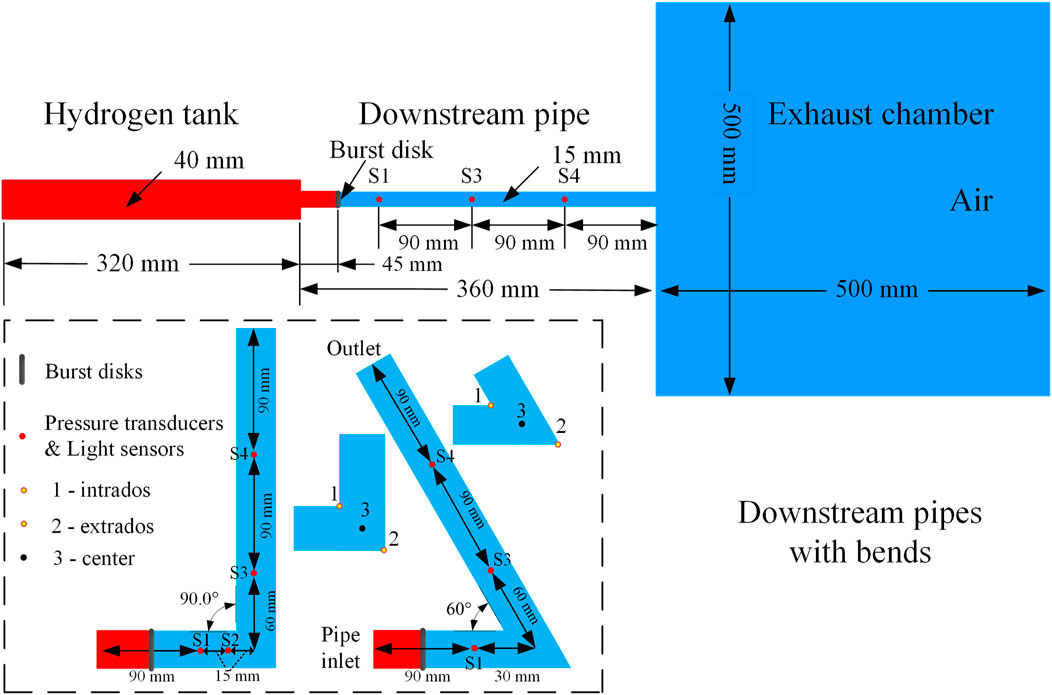
Figure 1. Schematic of experimental facility as well as the computational domain. The lower graph shows an enlarged view of three downstream pipes with bend angles of 90° and 60°, respectively.
The simulations are partially based on the in-house code, which is a three-dimensional parallel semi-implicit density-based computational fluid dynamics (CFD) code for hydrogen explosion risk analysis. The LES filtered governing equations for this study include the conservation equations of mass, momentum, energy, chemical species, and the state. The arbitrary Lagrangian-Eulerian approach, developed by Hirt (Hirt et al., 1997), is employed to solve the full Navier-Stokes equations for the purpose of covering all-speed flow. The compressible linear eddy model (LEM) was introduced as a subgrid model to investigate the role of turbulent mixing. In the LEM approach, spatial or temporal scales are resolved down to the minimum turbulence scales for each LES cell in one-dimensional formulation; thus, it makes small-scale resolution computationally affordable. Also, LEM has apparent advantages for turbulent mixing interacting with flame attributed to the explicit distinction between molecular diffusion, turbulence, and chemical reaction. Previous studies implied that the LES-LEM model presented promising predictions in non-premixed/partially premixed flame (Li et al., 2016; Zhou et al., 2016) and detonation flame (Maxwell et al., 2018). The numerical convective fluxes are evaluated by the HLLC scheme (van Leer, 1979) for shock capture.
Accurate calculation of the flame front is vital for hydrogen ignition and detonation simulation. The average reaction progress variable c in the transport equation (density-weighted) is computed (Ettner et al., 2014) to describe combustion by defining c = 1 for the completely burnt gas and c = 0 for fresh gas. The turbulent burning velocity, ST, can be obtained by implementing the turbulent flame speed closures. Furthermore, the polynomial dependence of ST on molar hydrogen fraction based on experiments is applied for robustness consideration (Konnov, 2008).
The gaseous mixture delay time in autoignition, tign, is a function of mixture fraction fH, pressure p, and temperature T. Here, mixture fraction fH is defined as hydrogen atom mass fraction in each cell. Since detonation waves consist of shock compression and subsequent reaction zone, an accurate ignition delay time is critical in determining the induction time and induction parameter. The induction parameter, which would be α = 1 when the unburned gas mixture is completely compressed or heated, indicates that an exothermic reaction will start. The source term controlled by chemical kinetics uses a detailed chemistry mechanism proposed by Conaire (Ó Conaire et al., 2014) with a reaction model comprised of 9 species and 20 elementary reactions for describing hydrogen detonation. This mechanism is preferred because it behaves well for both the ignition delay time and the heat release within a wide pressure/temperature range (Ströhle and Myhrvold, 2007). To avoid frequent re-computation of the local ignition delay time, a table of tign as a function of T, p, and fH is generated for convenience. The CFD code can access this table and gain the ignition delay time in each cell at any time step. Additionally, a sub-model (Li et al., 2016) is introduced to increase the autoignition modeling accuracy on relatively coarser grids. Thermal properties for the hydrogen-air mixture were cited from the Chemkin database, and molecular transport coefficients were calculated by the Sutherland correlation.
The accuracy of second-order time for multi-dimensional system is achieved by the operator splitting method. The code is both applicable for slow hydrogen deflagration, as well as supersonic flows and combustion-driven compressible flows. Simulations are conducted for the domain shown in Figure 1 without exhaust chamber. High pressure hydrogen was compressed in the tank (red color) and blocked by a flat disk. At the initial moment the non-inertial burst disk was thought instantaneously removed to induce the discontinuity decay. The atmospheric condition of air was taken as 101 kPa and 298 K. The air composition was adopted as 23 mas% of oxygen and 77 mas% of nitrogen. Non-slip impermeable adiabatic boundary conditions were applied for all wall surfaces. Non-reflecting far field boundary conditions for pressure were used for the downstream outlet and radial boundaries of the exhaust chamber. Flat pressure boundary (Lee et al., 2015) was adopted for the rupture disk.
In the LEM model, calibration was required for model parameters before the calculation considering the flow field evolution. Firstly,
where
and
respectively. Here, Cv is a constant related to Kolmogorov number, which has a significant influence on flame-shock interaction, researchers have addressed this in reference (Maxwell et al., 2018), where a series of validation studies and sensitivity analyses were reported. Additionally, N represented the number of elements in each LES cell. Cv and N were set as 0.045 and 9 in present study, respectively. As the primary focus of this article is on the physical phenomena associated with hydrogen detonation waves rather than the intricacies of the modeling approach, we have provided a concise summary of the governing equations (Eqs 1–3) and the model parameters as they are implemented. These parameters have been directly adopted from our previous work, where a comprehensive calibration process was described. We refer readers to our former paper, as indicated in reference (Zhou et al., 2016), for an in-depth discussion of the rationale and methodology behind the parameter choices.
A Cartesian grid system was used for downstream pipes with uniform size as well as a boundary layer refinement. To eliminate the influence of mesh size, tests with three types of mesh resolution including 60 μm, 30 μm and 15 µm were performed. In Figure 2, pressure evolutions of transducer S2 in pipe with 90° bend are presented by simulation. It’s found that the calculation curve for mesh of 30 µm is very close to that of 15 μm, especially in prediction of arrival time of leading shocks and reflected shocks. By density contours at 125 µs around the bends shown in Figure 3, it can be seen that the overall density distributions are similar, however, the position of incident shock is more identical for grid sizes of 30 μm and 15 µm. Based on the results in Figure 2 and 3, 30 µm-sized grid was adopted for all cases. Since the simulation were conducted by detailed chemistry with high cost of computation, the uniform grid width for all cases was set to be 30 µm for the downstream pipes uniformly, and the major grids for the pressure tank were 200 µm for a compromise. The total number of the cells was approximately 5.6 million.
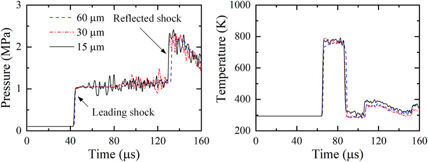
Figure 2. Grid convergence study with pressure and temperature evolutions (90°-pipe, burst pressure: 2.18 MPa).
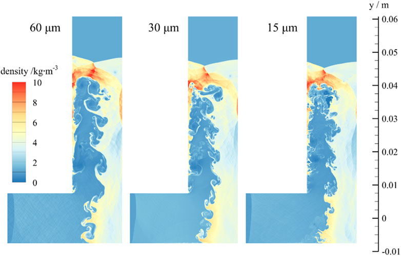
Figure 3. Density distributions at 120 µs with three resolutions (90°-pipe, burst pressure: 2.18 MPa).
Figure 4 depicts a comparison between experimental and numerical results of pressure variations observed in a pipe with a 90° bend and a burst pressure of 6.21 MPa. The moment denoted as t1 corresponds to when the initial group of shock waves passes the pressure transducer S1, resulting in the expansion waves inside the pipe, which is marked by a pronounced pressure surge. The correspondence between the experimental data and the simulation is quite satisfactory, particularly with respect to the arrival times of the subsequent shock waves, indicated by t2, t3, and t4.
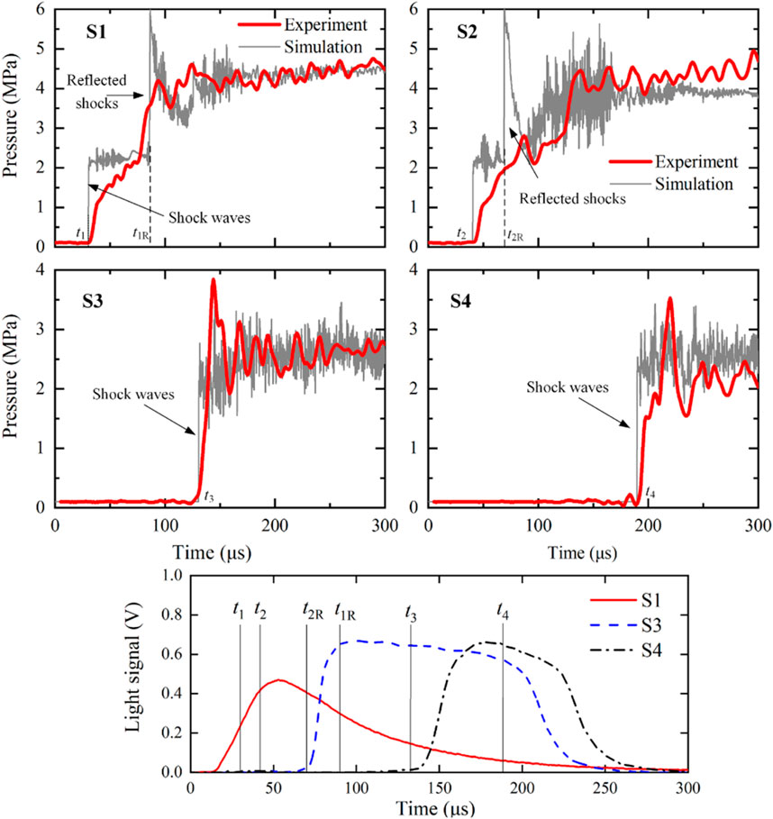
Figure 4. Upper 4 graphs: comparison between pressure transducer measurements and numerical results with burst pressure of 6.21 MPa and angle of 90°; Lower graph: photo-diodes signals at S1, S3, and S4.
The temporal resolutions for experiments and simulations are 0.1 ms and 0.02 ms, respectively. Additionally, the experimental data has been subjected to a 10-point smoothing average for reducing noise and clarifying the overall trend. Due to these reasons, the simulations are able to depict the dynamics of reflected shocks with more clarity and definition as compared to the experimental data. Therefore, the following analysis are mainly focused on the simulation results.
As depicted in Figure 4, an oscillatory pattern in the pressure waves between times t1 and t1R is indicative of self-ignition having transpired. This is reflected by a narrower variation range in the pressure readings of transducer S2 between t2 and t2R when compared to those of S1, suggesting an increased intensity of ignition at the location of sensor S2. This interpretation is bolstered by the concurrent experimental light sensor data, which reveal a rising trend in the photodiode signals from S1 between t1 and t2. From this observation, it may be inferred that the numerical results provide a richer depiction of the pressure wave characteristics, thereby affirming the capability of the numerical method to furnish an in-depth explanation of the ignition mechanism.
The presence of a high-pressure hydrogen discharge into a pipe with a bend is hypothesized to result in the generation of reflected shock waves. These reflections are postulated to account for the elevated pressure readings registered by S1 and S2, markedly surpassing those recorded by transducers S3 and S4. Notably, sensor S2 captures a peak pressure value, approximately thrice the magnitude of the stable propagating shock wave, at time t2. Despite the brevity of the oscillatory phase of this reflected pressure, the insights deduced from these limited measurements are corroborated by the experimental findings reported in reference (Uchida et al., 2011). Beyond the 200 µs mark, the intensity of the oscillations at S2 exhibits a discernible decrease, potentially attributable to the forward movement of the ignited flame and the resurgence of dominance by the hydrogen expansion waves.
The pressure of the reflected wave serves as a metric for the vigor of the transverse shock wave. Figure 5 illustrates that a pipe with a 60° bend induces a more intense reflected shock wave. The simulation outputs, which represent an averaged value over 50 µs commencing at the peak pressure point, generally exhibit strong concordance with experimental observations. Variations observed in the high-pressure burst region may be attributable to the real-gas effects or the omission of heat conduction between the gas and the solid boundaries. Furthermore, a smaller bend angle in the pipe leads to a greater deflection in flow, resulting in multiple shock waves reflecting along the upstream direction with augmented intensity.
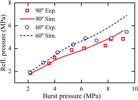
Figure 5. Comparison of the pressure of reflected shock wave against the burst pressure between experimental and numerical results computed for 90°- and 60°-pipes.
The average speed of the shock wave can be determined from the timing of detections by the pressure transducers and their intervening distances, as demonstrated in Figure 6. The velocity of the incident shock wave diminishes as it navigates through the bend. This attenuation is due to the cumulative effect of expansion waves produced when preceding waves collide with the walls, which reduces both the pressure and the momentum of the incident shock wave. Notably, in certain scenarios, the mean velocity of the shock wave actually increases after negotiating the corner. This acceleration is attributed to the more pronounced effects of reflections from subsequent shock waves and the interaction between shocks and vortices, which eclipse the dampening influence of expansion waves stemming from auto-ignition phenomena within the bends.
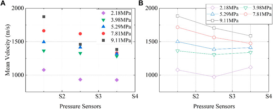
Figure 6. Pressure wave speed against distance (represent by pressure transducers’ location) along the 90°-pipe, (A) experimental, (B) numerical results (shapes with line).
The phenomenon of spontaneous ignition during high-pressure hydrogen release into straight pipes has been the subject of extensive investigation. The summarized understanding of the process involves a shock wave that travels into the ambient air, heating it through compression. The highest temperatures are typically observed within the boundary layer, where a decrease in velocity and a significant magnitude of vorticity prevail. Under critical conditions, this setup triggers spontaneous ignition, facilitated by turbulent mixing and the thermal effects of shock waves, as detailed in references (Uchida et al., 2011; Bragin et al., 2013; Lee et al., 2015). Figure 7 provides insights into the self-ignition process, showcasing the temporal evolution of temperature and hydroxyl (OH) mass fractions. Generally, the shock wave is followed by a contact surface which separates the cold hydrogen and the heated mixture, as depicted. The thickness of the heated air layer, demarcated by the isoline fH = 0, expands progressively over time. If the shock-vortex interaction in strong enough, chemical reaction will propagate in the direction from the wall to the pipe center as the contact surface propagates downstream. Given the thorough analysis of ignition mechanisms in straight sections, our investigation is primarily concerned with the variation in physical phenomena occurring within the bent regions of the pipe.
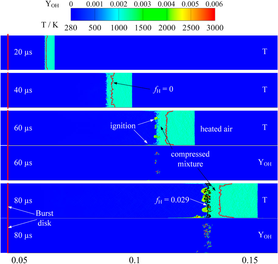
Figure 7. Ignition process interpreted by temperature (T) and OH mass fraction (YOH) profiles in straight pipe (burst pressure: 5.40 MPa).
In scenarios involving a straight pipe with a burst pressure of 2.18 MPa, neither experimental observations nor simulations indicate the onset of ignition. However, the presence of flames was registered by light sensors S3 and S4 under identical conditions in pipes with 90° and 60° bends. To explain the discrepancies observed in these configurations, simulations with burst pressure of 2.18 MPa were conducted.
Figures 8, 9 presents temperature variations over time in the 90°- and 60°-pipes respectively. The figures start from 95 µs, this initial time step, the pressure wave front has collided with the wall and reflected, forming a localized high-temperature and pressure zone around the bend that is not yet conducive to ignition. Isolines of stoichiometric mixture fraction (fH = 0.029) and mixture/air contact surface (fH = 0) are also shown in Figure 8. At this moment the reflected shocks are about to colliding with following mixtures which could be distinguished by isoline fH = 0. By 100 µs, the clearly defined boundaries of the reflected shock begin to deform and exhibit a wrinkled texture, indicating the heating of the mixture and the formation of small vortices in close proximity to the stoichiometric line induced by the collision process. The resulting vortices enhance turbulent mixing and promote heat transfer. Consequently, spontaneous ignition is observed at 102 µs within a region adjacent to and slightly richer than the stoichiometric line. Disturbance in the vicinity of isoline of fH = 0 is weak, and most vortices are observed in the rich mixture (except in the boundary layers), which means that the chemical reaction rate is very limited. However, with the contact between the first group of shocks and the inner wall surface, the heated air and mixture will be further heated due to compression and deceleration. Then reflected waves will be generated continuously and interact with subsequent pressure waves, as seen in the figures from time 100–140 µs. Within this interval, the air trailing strong shock fronts is substantially heated, creating conducive conditions for hydrogen reactions. The air behind strong shocks is readily heated for the hydrogen to react. Enlarged figures of ignition region from 102 to 115 µs are also shown in Figure 8. It is found that shock interactions with chemistry can create mixing and reacting regions such as a vortex ring in the bent area. Therefore, spontaneous ignition can be initiated and developed more easily.
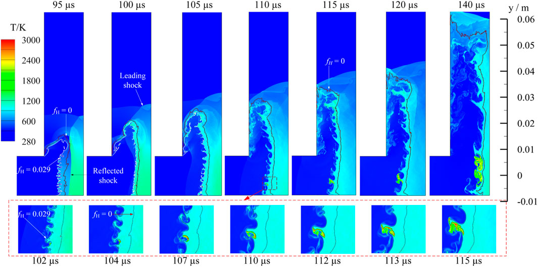
Figure 8. Top: temperature field variations in 90°-pipe (burst pressure: 2.18 MPa) with isolines of mixture fraction. Bottom: detailed development of ignition regions.
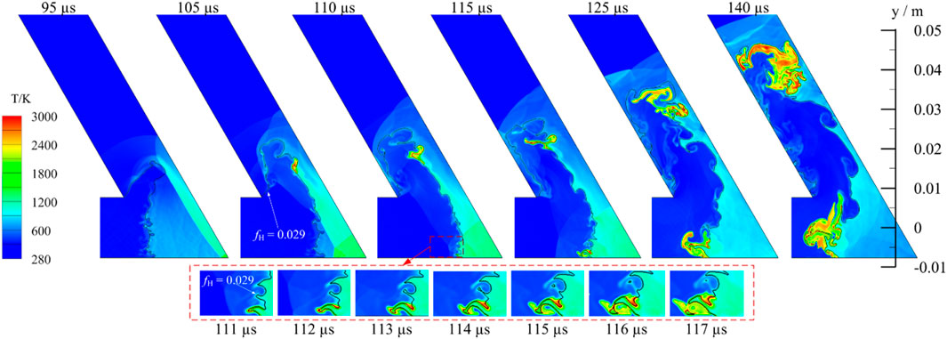
Figure 9. Top: temperature field variations in 60°-pipe (burst pressure: 2.18 MPa) with stoichiometric line. Bottom: detailed development of ignition regions.
Figure 9 depicts the spontaneous ignition process within the 60° pipe. The hot, reflected shocks colliding with compressed mixtures result in higher temperatures and more reactive mixtures, potentially decreasing ignition delay and facilitating ignition. Nevertheless, two ignition regions exist in 60° pipe. Ignition dynamics of the lower one are comparable to those observed in 90° pipe, albeit with a delayed ignition onset and an accelerated growth rate, as evidenced by the magnified details in the lower portion of Figure 9. The reason is attributed to that the reflected pressure wave interaction is stronger due to more violent deceleration. For pressure waves passing the intrados (point 1 showed in Figure 1) in both pipes, wave diffraction is observed continuously which resulting in considerable vortex. Moreover, the diffraction will collide with the reflected, heated air from 95 µs which leads to self-sustained ignition in the higher region. Compared to the case in 90° pipe, the same diffraction pressure wave fails in ignition. The reason maybe that the colliding in 60° pipe is more strenuous and the reflected air is more compressed and heated. One proof is that the heated air region downstream is thinner in 60° pipe.
To gain insights into the ignition mechanism and flame structure from a statistical perspective, scatter plots correlating temperature and mixture fraction at varying temporal stages are illustrated in Figure 10. The scatter data represented in Figure 10 was gained from comprehensive spatial sampling across the entire domain, ranging from the burst disk to the end of the pipe. The equilibrium temperature—computed based on a standard condition of 298 K and 1 atm—is delineated via red dashed lines. Initially, an uptick in temperature is observed within fuel-lean mixtures, followed by the temperature peak transitioning towards richer mixtures. This shift significantly demonstrates that ignition preferentially initiates under hot or stoichiometric conditions, featuring a shorter ignition delay. This phenomenon is different from premixed flame where auto-ignition starts from fuel-lean area (Echekki and Chen, 2003). Temperature reaches maximum in stoichiometric mixture fraction, and then decreases to a stable value from fH approximately equal to 0.1. This finding suggests that self-ignition transpires within a notably confined range of mixture fractions, with the most reactive mixtures situated close to stoichiometry. The relationship between mixture fraction and ignition propensity is corroborated by the data presented in Figure 7, which outlines the temperature profiles, and Figure 10, which details the ignition occurrences across different mixture fractions. The alignment of data between these figures provides a cross-validation for the conclusion that stoichiometric mixtures are the most reactive and, therefore, the most likely to undergo self-ignition under conducive conditions. According to temperature ranges and distributions, it can be concluded that reactions in 60°-pipe are more intensive than in 90°-pipe. Furthermore, extensive non-reacting but heated mixtures for all cases imply that flame propagation even detonation is promising.
Figure 11 presents numerical results of temperature profiles in a 90° pipe subjected to a burst pressure of 6.40 MPa, examining the influence of bend geometry on the downstream flame structure. Illustrated alongside are the stoichiometric mixture fraction (fH = 0.029) marked by a blue solid line and the boundary demarcating the mixture from the air (fH = 0) indicated by a red solid line. Given the elevated burst pressure, ignition can occur almost instantaneously in the reactive region near the boundary layer, resulting in flame formation as the flow traverses the bend. At 56 µs, flame sustainability is compromised along the upper wall due to flame-shock diffraction; nonetheless, at 64 µs, the reflected shock waves intensify, creating a region of extremely high temperature. Consequently, any prior extinction is overcome, with re-ignition being consistently observed between 66 and 74 µs. This sequence of events leads to significant shock heating and the emergence of a self-sustaining flame that propagates through the remainder of the tube. Once again, the most reactive area is identified as being slightly rich in mixture. It is evident that flames develop more extensively in bent pipes compared to straight ones. As previously mentioned, vortices generated near the boundary layer after navigating the bend contribute to the widespread distribution of reaction zones. In contrast, in a straight pipe, the heated area is considerably broader, leading to a less turbulent mix and a more confined reaction space, as indicated by the OH profile in the lower graph of Figure 7. The presence of bends appears to enhance turbulent mixing, promoting reactions throughout the downstream regions. It is thus deduced that the flame propagating along the boundary layer is a result of turbulence-induced reactions.
Figure 12 presents the pressure profiles along the intrados (point 1 indicated in Figure 1), extrados (point 2), and the centerline (point 3) for three distinct types of pipes. The profiles are examined at the specific moment when the pressure wave reaches the pipe outlet, providing a snapshot of the pressure loads. As seen in Figure 2, the pressure typically exhibits high oscillations. To enhance the clarity of the graphical representation, a smoothing process has been applied to the sample data. In the straight pipe, the pressure readings do not display significant variation across different points on the pipe wall. Conversely, in the bent pipes, the pressure prior to the bend is notably higher, attributed to the effect of reflected waves. The calculated average pressures between sensors S1 and S2, as well as S3 and S2, reveal that the pressure drop escalates with decreasing bend angle. The pressure profiles clearly demonstrate that the pressure loads in the bent pipe sections are greater compared to the corresponding straight tube sections near the corner in the experiments involving bends.

Figure 12. Pressure records of centerline, inner wall and outer wall in the bends from three different pipes at time when pressure wave just arrive the pipe outlet (burst pressures: 6.40 MPa).
It is observed that the reactions within a 60° bend are significantly more intense than those in a 90° bend. This increased intensity is attributed to greater deceleration and subsequent compression of the gas mixture at sharper angles, which can enhance the likelihood of flame acceleration and possibly lead to detonation in confined spaces. In light of these insights, it is recommended the following practical measures for the design and safety of hydrogen storage and transport systems:
1) Minimize Sharp Bends: Where possible, design pipelines to avoid sharp bends. The usage of gentler curves helps to minimize abrupt decelerations and compressions that can escalate reaction intensities.
2) Smooth Transition in Bends: In cases where bends are necessary, they should be designed to provide a smooth transition for the hydrogen flow. This can be achieved through the use of larger bend radii or gradual directional changes, which can reduce the risks associated with rapid gas deceleration and compression.
3) Leakage Monitoring and Prevention: The potential for self-ignition and sustained flames, even from minor leaks under high pressure, underscores the critical need for rigorous leakage monitoring systems. It is essential to implement advanced detection technologies capable of identifying leaks promptly to initiate immediate corrective actions.
4) Safety Measures and Emergency Planning: Given the potential for intense flames and detonation, it is imperative to incorporate robust safety measures, including emergency shutoff valves and blast mitigation designs. Furthermore, emergency response plans should be in place and regularly rehearsed to ensure rapid and effective action in case of an incident.
5) Regular System Inspections: Frequent inspections and maintenance of the hydrogen transport infrastructure are crucial to identify and rectify potential hazards such as material fatigue, corrosion, or mechanical damages that could compromise the system’s integrity.
This study provides a comprehensive numerical analysis of the flow dynamics and the varied spontaneous ignition characteristics associated with hydrogen release through pipes with different bend geometries. The accuracy of model is validated by comparing with pressure histories of incident and the reflected shock wave. The results indicate that the intensity of the reflected shock wave is higher in a pipe with a smaller angle, and the maximum pressure appears when reflected shock is formed.
The numerical results show that the ignition mechanism is closely connected with the flow formation inside the straight pipe. The shock and vortex induced by boundary play an important role in ignition in the straight part by mixing with reaction regions in the boundary layer of the pipe. For condition with low burst pressures, ignition cannot be successful in the straight part. Spontaneous ignition is induced by collision between reflected, heated shock and compressed mixture. The collision wrinkles the smooth boundary of reflected waves and produces substantial vortices beyond of the scope of boundary layers which enhance heat transfer and mixing. In addition, shock interactions can create mixing regions such as a vortex rings in the bent area which have facilitated the initiation of ignition. Reactions in 60° pipe are more intensive than in 90° pipe due to larger deacceleration and more compressed of heated mixtures. Based on mixture fraction analysis, it’s found that most ignitions take place in a narrow region around stoichiometric line. The most reactive and the highest temperature areas are observed in the vicinity of stoichiometric line but more likely in a fuel-rich area. The pressure profiles along the side wall, intrados and extrados indicate that pressure loads greater than the straight tube portion near the corner in the bent experiments. It can be concluded that bend structures make spontaneous ignition easier.
These practical insights aim to guide industry stakeholders in enhancing the safety profile of hydrogen storage and transport facilities, contributing to safer and more reliable hydrogen energy systems. Building on the insights gained from this study, future investigations will focus on detailed analysis of pipe geometries, scalability to real-world infrastructure and high-pressure cryogenic leak dynamics.
The original contributions presented in the study are included in the article/Supplementary material, further inquiries can be directed to the corresponding author.
XZ: Conceptualization, Methodology, Project administration, Writing–review and editing. JJ: Formal Analysis, Software, Writing–original draft. CC: Formal Analysis, Writing–original draft. LH: Data curation, Resources, Writing–review and editing.
The author(s) declare financial support was received for the research, authorship, and/or publication of this article. Natural Science Foundation of Xiamen, China (No. 3502Z202371015).
Author LH was employed by the China Nuclear Power Design Co., Ltd.
The remaining authors declare that the research was conducted in the absence of any commercial or financial relationships that could be construed as a potential conflict of interest.
All claims expressed in this article are solely those of the authors and do not necessarily represent those of their affiliated organizations, or those of the publisher, the editors and the reviewers. Any product that may be evaluated in this article, or claim that may be made by its manufacturer, is not guaranteed or endorsed by the publisher.
Blanchard, R., Arndt, D., Grätz, R., Poli, M., and Scheider, S. (2010). Explosions in closed pipes containing baffles and 90-degree bends. J. Loss Prev. Proc. 23, 253–259. doi:10.1016/j.jlp.2009.09.004
Bragin, M., Makarov, D., and Molkov, V. (2013). Pressure limit of hydrogen spontaneous ignition in a T-shaped channel. Int. J. Hydrogen Energy 38, 8039–8052. doi:10.1016/j.ijhydene.2013.03.030
Duan, Q., Xiao, H., Gao, W., Gong, L., and Sun, J. (2016). Experimental investigation of spontaneous ignition and flame propagation at pressurized hydrogen release through tubes with varying cross-section. J. Hazard. Mat. 15, 18–26. doi:10.1016/j.jhazmat.2016.08.005
Echekki, T., and Chen, J. H. (2003). Direct numerical simulation of autoignition in non-homogeneous hydrogen-air mixtures. Combust. Flame. 134, 169–191. doi:10.1016/S0010-2180(03)00088-9
Ettner, F., Vollmer, K. G., and Sattelmayer, T. (2014). Numerical simulation of the deflagration-to-detonation transition in inhomogeneous mixtures. J. Combust. 2014, 1–15. doi:10.1155/2014/686347
Golovastov, S., and Bocharnikov, V. (2012). The influence of diaphragm rupture rate on spontaneous self-ignition of pressurized hydrogen: experimental investigation. Int. J. Hydrogen. Energy 37, 10956–10962. doi:10.1016/j.ijhydene.2012.04.070
Gong, L., Duan, Q., Jin, K., and Sun, J. (2016). Experimental study of pressure dynamics, spontaneous ignition and flame propagation during hydrogen release from high-pressure storage tank through 15 mm diameter tube and exhaust chamber connected to atmosphere. Fuel 182, 419–427. doi:10.1016/j.fuel.2016.05.127
Gong, L., Duan, Q., Sun, Q., Jin, K., and Sun, J. (2017). Effects of the geometry of downstream pipes with different angles on the shock ignition of high-pressure hydrogen during its sudden expansion. Int. J. Hydrogen Energy 42, 8382–8391. doi:10.1016/j.ijhydene.2017.02.025
Guo, C., Wang, C., Xu, S., and Zhang, H. (2007). Cellular pattern evolution in gaseous detonation diffraction in a 90°-branched channel. Combust. Flame 148, 89–99. doi:10.1016/j.combustflame.2006.11.001
Gwak, M., and Yoh, J. (2013). Effect of multi-bend geometry on deflagration to detonation transition of a hydrocarbon-air mixture in tubes. Int. J. Hydrogen. Energy 38, 11446–11457. doi:10.1016/j.ijhydene.2013.06.108
Hirt, C., Amsden, A., and Cook, J. (1997). An arbitrary Lagrangian-Eulerian computing method for all flow speeds. J. Comput. Phys. 135, 203–216. doi:10.1006/jcph.1997.5702
Kaneko, W., and Ishii, K. (2016). Effects of diaphragm rupturing conditions on self-ignition of high-pressure hydrogen. Int. J. Hydrogen Energy 41, 10969–10975. doi:10.1016/j.ijhydene.2016.04.211
Kim, Y., Lee, H., Kim, S., and Jeung, I. (2013). A flow visualization study on self-ignition of high-pressure hydrogen gas released into a tube. Proc. Combust. Inst. 34, 2057–2064. doi:10.1016/j.proci.2012.07.020
Konnov, A. A. (2008). Remaining uncertainties in the kinetic mechanism of hydrogen combustion. Combust. Flame. 152, 507–528. doi:10.1016/j.combustflame.2007.10.024
Lee, H., Park, J., Kim, S., Kim, S., and Jeung, I. (2015). Numerical study on the spontaneous-ignition features of high-pressure hydrogen released through a tube with burst conditions. Proc. Combust. Inst. 35, 2173–2180. doi:10.1016/j.proci.2014.07.055
Li, J., Ren, H., and Ning, J. (2013). Numerical application of additive Runge-Kutta methods on detonation interaction with pipe bends. Int. J. Hydrogen. Energy 38, 9016–9027. doi:10.1016/j.ijhydene.2013.04.126
Li, L., Li, J., Teo, C., Chang, P., and Khoo, B. (2018). Experimental study on incident wave speed and the mechanisms of deflagration-to-detonation transition in a bent geometry. Shock Waves 28, 205–216. doi:10.1007/s00193-017-0721-0
Li, S., Zheng, Y., Martinez, D. M., Li, S., Zhu, M., and Jiang, X. (2016). “A LES-LEM study of preferential diffusion processes in a partially premixed swirling combustor with synthesis gases,” in Proceedings of the ASME Turbo Expo 2016: Turbomachinery Technical Conference and Exposition, Seoul, South Korea, June 13–17, 2016 (New York, NY: ASME). Volume 4B: Combustion, Fuels and Emissions. doi:10.1115/GT2016-57146
Maxwell, B., Pekalski, A., and Radulescu, M. (2018). Modelling of the transition of a turbulent shock-flame complex to detonation using the linear eddy model. Combust. Flame. 192, 340–357. doi:10.1016/j.combustflame.2018.02.013
Nuclear and Industrial Safety Agency and Ministry of Economy (2002). Trade and Industry Japan, Investigation report on pipe rupture incident at Hamaoka. Nucl. Power Stn. Unit-1. doi:10.3327/jaesj.44.784
Ó Conaire, M., Curran, H. J., Simmie, J. M., Pitz, W. J., and Westbrook, C. K. (2014). A comprehensive modeling study of hydrogen oxidation. Int. J. Chem. Kinet. 36, 603–622. doi:10.1002/kin.20036
Ströhle, J., and Myhrvold, T. (2007). An evaluation of detailed reaction mechanisms for hydrogen combustion under gas turbine conditions. Int. J. Hydrogen Energy 32, 125–135. doi:10.1016/j.ijhydene.2006.04.005
Sulaiman, S., Kasmani, R., Kiah, M., Kidam, K., Hassim, M., Ibrahim, N., et al. (2014). The influence of 90 degree bends in closed pipe system on the explosion properties using hydrogen-enriched methane. Chem. Eng. Trans. 36, 271–276. doi:10.3303/CET1436046
Uchida, M., Suda, T., Fujimori, T., Fujii, T., and Inagaki, T. (2011). Pressure loading of detonation waves through 90-degree bend in high pressure H2–O2–N2 mixtures. Proc. Combust. Inst. 33, 2327–2333. doi:10.1016/j.proci.2010.06.152
van Leer, B. (1979). Towards the ultimate conservative difference scheme. V. A second-order sequel to Godunov's method. J. Comput. Phys. 32, 101–136. doi:10.1016/0021-9991(79)90145-1
Yuan, X., Zhou, J., Lin, Z., and Cai, X. (2016). Adaptive simulations of detonation propagation in 90-degree bent tubes. Int. J. Hydrogen Energy 41, 18259–18272. doi:10.1016/j.ijhydene.2016.07.130
Keywords: spontaneous ignition, bent pipes, Pressurized hydrogen, large eddy simulation, detailed chemistry
Citation: Zhou X, Jing J, Chen C and He L (2024) Physics of pressurized hydrogen spontaneous ignition in pipes containing bends of different angles. Front. Energy Res. 12:1383759. doi: 10.3389/fenrg.2024.1383759
Received: 08 February 2024; Accepted: 13 March 2024;
Published: 02 April 2024.
Edited by:
Haotian Liu, University of California, Los Angeles, United StatesReviewed by:
Yunzhi Chen, The University of Utah, United StatesCopyright © 2024 Zhou, Jing, Chen and He. This is an open-access article distributed under the terms of the Creative Commons Attribution License (CC BY). The use, distribution or reproduction in other forums is permitted, provided the original author(s) and the copyright owner(s) are credited and that the original publication in this journal is cited, in accordance with accepted academic practice. No use, distribution or reproduction is permitted which does not comply with these terms.
*Correspondence: Xuejin Zhou, emhvdXhqQGhxdS5lZHUuY24=
Disclaimer: All claims expressed in this article are solely those of the authors and do not necessarily represent those of their affiliated organizations, or those of the publisher, the editors and the reviewers. Any product that may be evaluated in this article or claim that may be made by its manufacturer is not guaranteed or endorsed by the publisher.
Research integrity at Frontiers

Learn more about the work of our research integrity team to safeguard the quality of each article we publish.