 Hamza Waqar1
 Abdul Wadood
- 1Department of Electrical Engineering, The University of Azad Jammu and Kashmir, Muzaffarabad, Pakistan
- 2Renewable Energy and Environmental Technology Center, University of Tabuk, Tabuk, Saudi Arabia
- 3Electrical Engineering Department, Faculty of Engineering, University of Tabuk, Tabuk, Saudi Arabia
The integration of Distributed Energy Resources (DERs) into distribution grids has become increasingly feasible and sustainable due to the development of microgrids. However, the development of an effective protection strategy remains a challenge in the implementation of microgrids. To address this challenge, this paper presents a simple and novel microgrid protection method based on superimposed components, Wigner distribution function (WDF) and alienation index-based. The proposed method develops a new fault detection index (FDI) by applying the alienation coefficient and WDF on a superimposed current signal to detect faulty events in the microgrid. The scheme is inherently phase segregated because the FDI is obtained for each phase individually. In addition, the proposed strategy introduces a new fault zone identification method based on the superimposed positive sequence reactive power (SPSQ). After obtaining the complete fault information, a relevant trip signal is generated to isolate the faulty section from the rest of the grid. The proposed methodology is evaluated through simulations using MATLAB/SIMULINK software. Various fault types, with varying parameters are simulated to validate the proposed approach. The results indicate that the proposed methodology is capable of recognizing, classifying, and locating all fault types in both grid-connected and islanded modes of operation.
1 Introduction
A microgrid (MG) is a small-scale power distribution network that is composed of DERs, energy storage devices, and electrical loads. MGs can operate in both parallel and standalone/islanded modes, which ensures a reliable power supply and enhances the overall efficiency of the system (Bukhari et al., 2018). However, the implementation of microgrids presents some significant protection challenges. The protection challenges associated with microgrids include the bidirectional power flow, the presence of ring feeder and varying short circuit levels resulting from different modes of operation. In situations, when a MG functions autonomously, i.e., in islanded mode, the fault current produced by the inverter-based DERs is limited to 2–3 times the rated current by the inverter control system (Elkhatib and Ellis, 2017; Bukhari et al., 2022). In contrast, the contribution of the utility grid to the fault current results in higher fault currents during grid-connected operation. Traditional overcurrent relays can only protect grid-connected MGs because the presence of DERs and islanded mode of operation changes both the direction and magnitude of fault current (Sharma and Samantaray, 2019; Bukhari et al., 2021). Therefore, a protection strategy is essential to ensure the secure, adaptable, and consistent operation of MGs in both grid-connected and standalone modes.
Several protection strategies have been developed to ensure the safe and reliable operation of MGs. In (Sharma and Samantaray, 2019), a protection method based on integrated impedance angle was presented for microgrids that utilized wide-area positive sequence components of voltages and currents measured by phasor measurement units. The impedance angle was computed using data from both ends of the line and was used as a primary indicator for faults detection and location in MGs. In (Elkhatib and Ellis, 2017), the authors developed a new impedance-based protection scheme that used communication to track impedance trajectories at various feeder relays. In addition, directional elements were also employed to determine the direction of faults in MGs.
A communication assisted protection scheme with self healing capability was developed in (Gadde et al., 2022). The developed scheme used SEL 421-7 relay and hardware in loop for real-time implementation. The authors in (Elsadd et al., 2021) suggested a new protection method for deregulated distribution networks by using adaptive optimum overcurrent relays. This method was designed to reduce the inefficacy of traditional overcurrent protection under various fault conditions. In (Jain et al., 2018), an adaptive overcurrent relay-based dynamic protection method was presented for the primary protection of MGs. The maximum fault current contribution of DERs and status data of MGs were used to calculate the relay pickup currents. The coordination was achieved by blocking the signals between the relays. A new adaptive MG protection method based on digital overcurrent relay was developed in (Ghadiri and Mazlumi, 2020). The relay setting was divided into three parts by using a self-organizing map classification approach. In (Bamshad and Ghaffarzadeh, 2023), the miscoordination problem produced due to DERs was solved by using a quadratic multi-agent. Different agents were developed to handle specific protection and coordination issues, and a relay trip signal was generated to operate the breaker based on the output of all agents.
The authors in (Alam et al., 2021) introduced a new protection scheme for networked microgrids using directional overcurrent relays. The scheme had the ability to handle different connection statuses of microgrids in system. K-means clustering was used to divide the possible interconnections of microgrids into four groups. In (Alam, 2018), an interior point optimization solver-based adaptive relay coordination method was introduced. In case of a change in the operating condition of the MGs, the developed method offered the best relay settings for relay coordination based on fault current calculations of the network. To address coordination issues in both grid-connected and standalone modes, fault current limiters (FCLs) were used (Dehghanpour et al., 2016). In (Heidary et al., 2020), a high-temperature superconductive fault current limiter was developed that controlled the power flow in lines while limiting fault currents. On the other hand, a resistor and a set of inductive superconductor FCLs were used to limit the fault current of synchronous DERs (Sadeghi and Abasi, 2021).
To provide selectivity, some researchers had incorporated distance protection into microgrid protection (Brearley and Prabu, 2017). Such relays can protect the network in both grid-connected and standalone modes. In (Yin et al., 2021), a protection method utilizing a residual voltage correction and distance relay was proposed for the protection of microgrids against single-line-to-ground faults only. For ring distribution systems with a high DER penetration, the authors in (Tsimtsios et al., 2019) developed a pilot-based distance protection strategy that employed distance relays at both terminals of each main line section. The forward distance element was used to protect the feeders whereas the reverse distance element was used for buses and lateral protection. However, high impedance faults and bidirectional power flow in microgrids had a major impact on the efficacy of the developed protection method.
Different protection variables, such as current and voltage harmonics, sequence components, signal processing method and travelling waves can be used for MG protection. A protection method for inverter-based islanded MG was developed by using negative-sequence components and a definite-time grading technique (Zarei et al., 2019). However, this scheme did not consider balanced three-phase faults that lack negative sequence components. Moreover, unbalanced loads might cause additional issues in the suggested scheme. In (Saleh et al., 2020), a protection strategy based on synthetic harmonics was developed for inverter-based MGs. In the developed method, a voltage-restrained per-phase harmonic controller was added to the control system of the inverter of each DERs that injected up to three fictitious harmonic components in the current signal. The generated harmonics injected currents were collected locally by relays to decide the fault direction. The presented method was only applicable to inverter-based islanded microgrids. In (Dua et al., 2022), a protection scheme for microgrids with multi-energy DGs using positive sequence superimposed current differential angle was presented. The scheme used low-cost μ PMUs to measure current phasors. The scheme was tested with simulations and real-time control hardware-in-loop testing on different microgrid scenarios.
Various signal processing-based protection methods have also been developed for microgrids. A new protection method based on mathematical morphology was developed in (Peng et al., 2019). The wavefront polarity values were obtained at both terminals of the line to determine the presence of a fault in the line. However, this approach was not practical because of the 10 MHz sampling frequency. In (Langarizadeh and Hasheminejad, 2022), a differential protection strategy was presented by using the S-transform. The presented approach performed well for all types of faults in all operating modes of MGs. However, the scheme required a very long computing time. The authors in (Chaitanya et al., 2019) developed an improved differential protection method based on Hilbert transform and Variational mode decomposition. The developed approach used multiple threshold values to distinguish between various types of faulty events and normal switching transients. A differential line protection method was presented in (Nsengiyaremye et al., 2019) by using local fault identification and binary state outputs of the relays at both terminals of a distribution line. The scheme was flexible and simple and required a very low bandwidth communication system. In (Gururani et al., 2016), a Hilbert-Huang transform-based differential MG protection technique was proposed. The authors in (Chauhan et al., 2022) developed a protection method by using the rate-of-rise of fault current and an adaptive current threshold to provide quick and precise fault detection in MGs. The authors in (Qusayer and Hussain, 2024) presented a communication-assisted protection scheme for multi-microgrid using neural networks. The scheme identified and isolated faults in different operation modes and topologies. The scheme was tested with simulations and shows low delays and high effectiveness.
In (Awagan et al., 2021), the authors investigated decision tree (DT) and wavelet transform (WT)-based protection schemes for the distribution lines of an islanded hybrid MG. The instantaneous values of the signal obtained at the relay bus were pre-processed and features were extracted using WT. The features were then provided to DT to perform protection functions. In (Bukhari et al., 2020), a convolution neural network (CNN)-based approach was employed to identify and categorize the fault. The CNN classifier accurately distinguished between all healthy and faulty events in the MGs. The developed scheme provided extensive fault information to generate an appropriate trip signal for circuit breakers. In (Kulshrestha et al., 2020), a fault detection and classification method based on the Wigner distribution function and Stockwell transform has been presented for power networks with photovoltaic (PV) penetration. However, the proposed scheme was specifically designed for PV-based grid-connected networks and does not consider the low fault current levels typically found in the islanded mode of operation.
However, there is a significant research gap in the current state of research on microgrid protection strategies. Some of the studies mentioned above rely on synchronized measurement and communication medium (Elkhatib and Ellis, 2017; Sharma and Samantaray, 2019; Tsimtsios et al., 2019; Zarei et al., 2019; Yin et al., 2021), which makes them vulnerable to potential communication failures. Additionally, certain schemes (Tsimtsios et al., 2019; Yin et al., 2021) are only applicable to inverter-interfaced microgrids. Adaptive overcurrent protection schemes (Jain et al., 2018; Ghadiri and Mazlumi, 2020; Elsadd et al., 2021; Gadde et al., 2022; Bamshad and Ghaffarzadeh, 2023) necessitate prior knowledge of all operating scenarios and involve complex and sophisticated calculations to determine the relay settings. Fault current limiter (FCL)-based schemes (Dehghanpour et al., 2016; Alam, 2018; Alam et al., 2021) are expensive and impractical. Distance protection techniques (Brearley and Prabu, 2017; Sadeghi and Abasi, 2021) require precise measurements and are not suitable for MGs with small length distribution lines. Moreover, signal processing-based and intelligent microgrid protection methods (Gururani et al., 2016; Chaitanya et al., 2019; Nsengiyaremye et al., 2019; Peng et al., 2019; Zarei et al., 2019; Saleh et al., 2020; Dua et al., 2022; Langarizadeh and Hasheminejad, 2022) impose a substantial burden and necessitate a large amount of data during the training process. Furthermore, the selection and extraction of appropriate fault features are crucial and require expert knowledge in the field.
This paper introduces a novel methodology for fault identification, classification, and location in microgrids based on the Wigner distribution function and alienation index. Firstly, superimposed components of voltage and current are extracted from the measured voltage and current signals. Next, the fault detection index (FDI) is extracted from the superimposed current signals in the microgrid using the alienation coefficient and Wigner distribution function. The extraction of the FDI provides a comprehensive representation of the fault condition in the system. The FDI of each phase is then used to identify the faulty events by comparing them to a predetermined threshold value. Then, superimposed positive sequence reactive power (SPSQ) is estimated to obtain the direction of the fault. Afterwards, the direction of fault at both ends of a line is compared to distinguish between external and internal faults. Finally, a trip signal is generated based on the above information to isolate the faulty section from the rest of the grid. The proposed methodology is evaluated through simulations using MATLAB/SIMULINK software. Various fault types, with varying resistance, location, and fault inception angle are simulated to validate the proposed approach. The results demonstrate that the proposed approach can accurately recognize, classify, and locate all fault types in both grid-connected and islanded modes of operation. The contributions of this study are as follows:
• The proposed protection method is very simple and does not require long calculations and has an easy implementation.
• A new superimposed components-based fault detection index (FDI) is developed from the Wigner distribution function and alienation index. This FDI enables the utilization of the same threshold value for both grid-connected and islanded modes of operation.
• A novel superimposed positive sequence reactive power (SPSQ)-based fault direction and fault zone identification technique is developed.
• The proposed method can protect MGs in all operating modes in radial and looped configurations against all types of solid faults.
The rest of the paper is organized as follows: Section 2 presents the proposed protection scheme in detail. Section 3 offers the details of the test system used for the validation. Simulation results are presented in Section 4. The comparison of the scheme is given in Section 5. Section 5 presents the conclusion of the paper.
2 Proposed protection scheme
This paper presents a novel protection method for MGs by utilizing the Wigner distribution function and Alienation coefficients. The proposed protection method consists of five modules, namely, data acquisition and preprocessing, fault detection and classification, fault direction estimation, fault zone identification, and trip signal generation modules. These modules work together to detect, classify, and locate faults in the MG. The block diagram of the proposed protection scheme is shown in Figure 1. Each module of the proposed scheme has been presented in detail as follows:
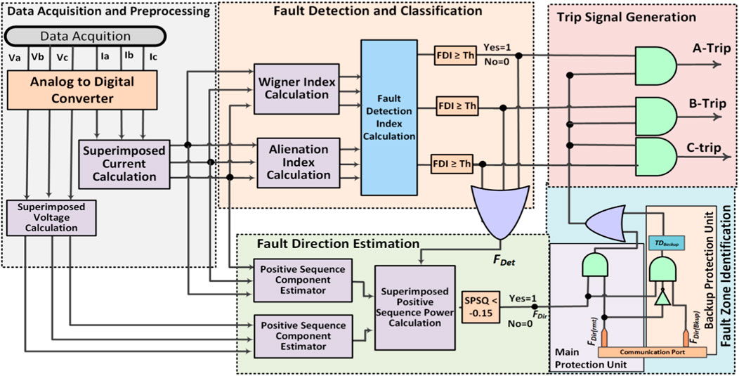
Figure 1. Schematic diagram of the proposed protection Scheme.
2.1 Data acquisition and preprocessing module
The data acquisition and preprocessing module initially acquires three-phase current and voltage signals at a relay point by using current and voltage transformers, respectively. The measured signals are then processed by a 12-bit analogue-to-digital converter having a sampling frequency of 3,840 Hz. The obtained signals are then used to calculate the superimposed components. The superimposed components of the three-phase current and voltage signals are obtained by subtracting the pre-fault/normal signal from the post-fault current/voltage signal (Awagan et al., 2021; Qusayer and Hussain, 2024). Mathematically, superimposed components can be expressed by Eq. 1:
Where XSIC(t) is the superimposed component at time t;
2.2 Fault detection and classification module
This module takes the three-phase superimposed current signals at the input and processes them by using the Wigner distribution function and alienation coefficients to develop a fault detection index (FDI) for fault detection and classification. The Wigner distribution is a mathematical tool that provides a time-frequency representation of a signal. It is defined as the joint time-frequency distribution of a signal. The Wigner distribution function for the superimposed current signal can be expressed by Eq. 2 (Ola et al., 2020; Ram Ola et al., 2020):
Where
The WI quantifies the energy concentration of a superimposed current in the time-frequency plane and tracks changes in the signal over time. The WI alone can be used for fault detection and classification. However, it may fail to track changes in islanding mode due to the small fault current level. Therefore, the proposed protection scheme also employs the alienation index (AI) along with WI.
The alienation index (AI) is a statistical measure that quantifies the amount of variance in a signal. It can be calculated using Eq. 4 (Ram Ola et al., 2020):
where AI is the alienation index, and r is the correlation coefficient. The correlation coefficient can be expressed as Eq. 5.
where x is the sum of superimposed current samples in a cycle measured at a time to, y is the sum of superimposed current samples in a cycle measured at the time
After obtaining the WI and AI from the superimposed current signal, a novel FDI is developed to detect and classify the faults. The developed FDI is obtained by multiplying the WI and AI, as given in Eq. 6.
The value of FDI should be zero during normal conditions because of the non-existence of the superimposed components. However, the FDI may have a small non-zero value under normal conditions due to noisy measurements, switching transients and load variations. Thus, a threshold of 100 is used on the FDI to avoid nuisance tripping in such conditions. Therefore, whenever the FDI crosses the threshold, the system is considered faulty. The proposed scheme calculates the FDI for each phase independently, so it does not require any additional fault classification algorithm.
2.3 Fault direction estimation unit
The fault direction estimation unit uses the superimposed positive sequence reactive power (SPSQ) to recognize the direction of the fault. The scheme involves the computation of superimposed reactive power by using superimposed positive sequence voltage and superimposed positive sequence current. The expression for the calculation of SPSQ is given in Eq. 7:
Where Isi1 and Vsi1 represent the positive sequence superimposed current and voltage respectively, and
2.4 Fault zone identification unit
In the proposed protection system, three adjacent relays communicate with each other for fault zone identification. These relays communicate with each other by sending either a “0” or “1” fault signal. A value of “1” specifies the existence of a forward fault, while a value of “0” indicates the nonexistence of a fault or a reverse fault. After receiving the signals from two adjacent relays, each relay determines the region in which a fault has occurred. Each protection relay is equipped with two protection zones - a main protection zone and a backup protection zone. The relay operates immediately when a fault occurs within the main protection zone whereas, the relay operates after a pre-specified time delay for the faults in the backup protection zone. This delay is necessary to allow the main protection of that zone to operate first, and it must be greater than the operating times of the primary protection relay and the associated circuit breaker. The block diagram of the fault zone identification is shown in Figure 2.
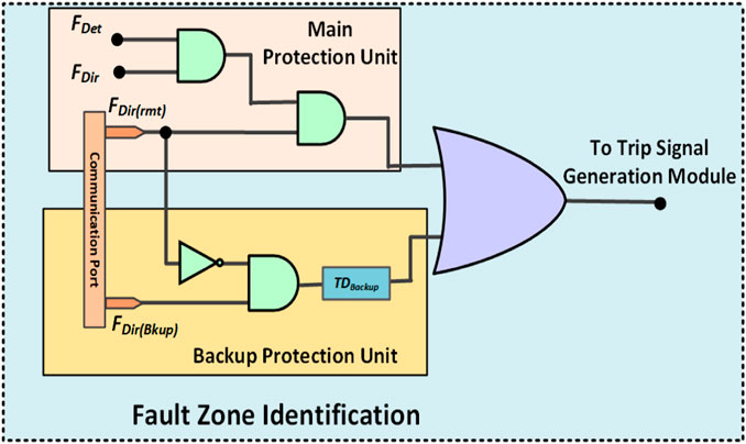
Figure 2. Fault zone identification module.
2.5 Trip signal generation
In the proposed protection method, the final step involves the generation of the trip signal upon detecting and locating a fault. A relevant trip signal is generated after receiving the fault occurrence, fault phase, and fault zone information from the fault detection and classification unit and fault zone identification unit. The generated trip signal is then used to operate the associated breaker in case of the occurrence of a forward fault within the zone of a relay.
3 Microgrid test system
This work uses a typical International Electrotechnical Commission (IEC) microgrid test system to validate the proposed protection method. The one-line diagram of the IEC microgrid is shown in Figure 3. The microgrid operates at 25 kV, and a 120/25 kV DYg transformer is employed to tie it to the main grid. The microgrid is composed of four DERs, including a synchronous generator, a photovoltaic system, wind turbines, and an energy storage device, linked to the MG by power electronics converters. To ensure the efficient working of the DERs in both standalone and grid-connected modes, a droop control scheme is implemented. The load and network parameters used in the simulations are given in Tables 1, 2.
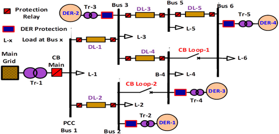
Figure 3. IEC microgrid test system.
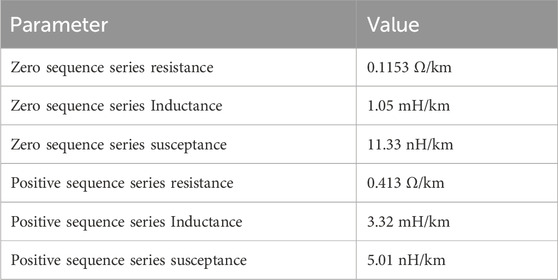
Table 1. Parameters of distribution lines for the IEC microgrid.
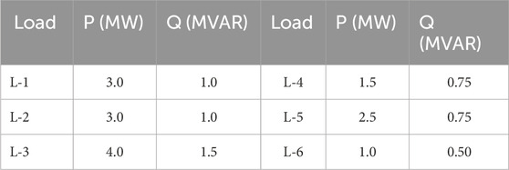
Table 2. Parameters of loads for the IEC microgrid.
4 Simulation results and discussion
To assess the effectiveness of the proposed protection method, exhaustive simulations were conducted on the IEC MG using MATLAB/SIMULINK software in both grid-connected and standalone modes. All ten types of short-circuit faults were created at each distribution line of the IEC microgrid under looped and radial configurations in both modes of operation.
4.1 Grid-connected mode
In grid-connected mode, the microgrid experiences significant transients as compared to the islanded mode because the main grid contributes to fault currents. Extensive simulations were performed by simulating all types of faults on each feeder of the MG to validate the usefulness of the proposed scheme in grid-connected mode. The three-phase current, FDI, SPSQ and Trip signal obtained at Bus-3 for a solid single-line-to-ground (B-G) fault at DL-4 of the test MG during grid-connected mode are shown in Figure 4. The FDI graph illustrates that the proposed fault index successfully detected the fault within one cycle. It is evident from the figure that the FDI of phase A exceeded the threshold, i.e. 100, while the FDI of the healthy phases remained below it. This verifies the fault classification capability of the proposed scheme for single-phase-to-ground faults. Furthermore, the negative value of the SPSQ for this fault confirms the effective operation of the fault direction unit.
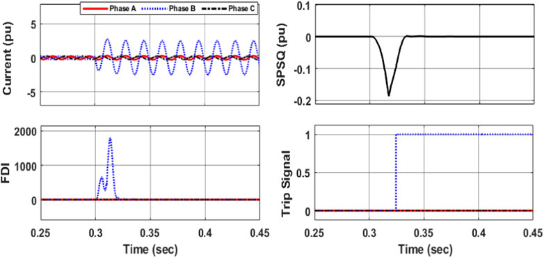
Figure 4. Simulation results obtained at Bus-3 during a solid B-G fault at DL-4 of microgrid in grid-connected mode.
To authenticate the operation of the presented method, extensive tests were also conducted by simulating the double line-to-ground fault at each line of the test microgrid. Figure 5 displays the simulation results obtained upstream of the line when an ABG fault hits the DL-1 of the microgrid. It can be seen from the figure that the FDIs of the faulty phases are greater than the threshold, i.e. 100 whereas it is less than the threshold for phase A which is a healthy phase. The SPSQ is negative because the fault is a forward fault for the relay point.
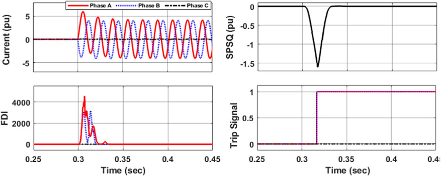
Figure 5. Simulation results obtained at upstream of DL-1 during an ABG fault at the line.
To confirm the operation of the proposed scheme in the looped configuration, an ACG fault at DL-1 of the microgrid was simulated. The looped configuration was achieved by closing the CB-1 and CB-2 of the test microgrid. The simulation results for the fault at Bus-3 are presented in Figure 6. The results demonstrate that the presented method operated successfully for the fault in the looped configuration.
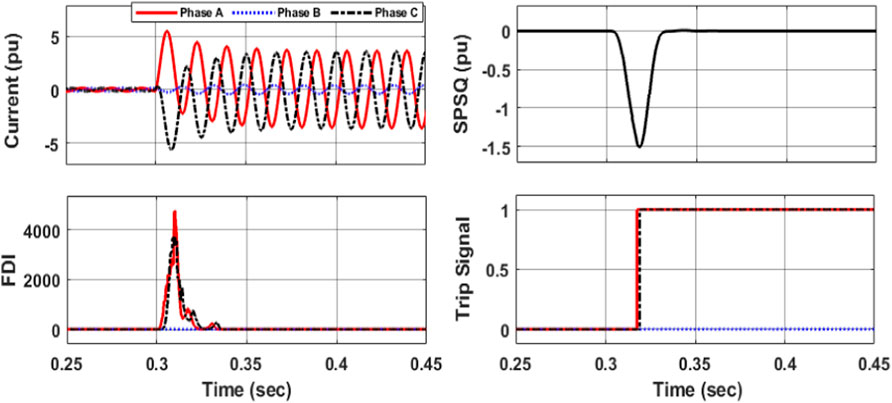
Figure 6. Simulation results obtained at upstream of DL-1 during an ACG fault in Looped Configuration.
To test the capability of the presented method during reverse faults, a three-phase fault was simulated at DL-3 of the IEC MG which is a reverse fault for the upstream relay of DL-5. The results obtained at the upstream relay of DL-5 are presented in Figure 7. The relay distinguished the fault successfully as FDIs for all the phases are greater than the threshold value. However, the SPSQ is positive in this case because the fault is a reverse fault for this relay. This verifies the effectiveness of the proposed scheme in case of reverses faults.
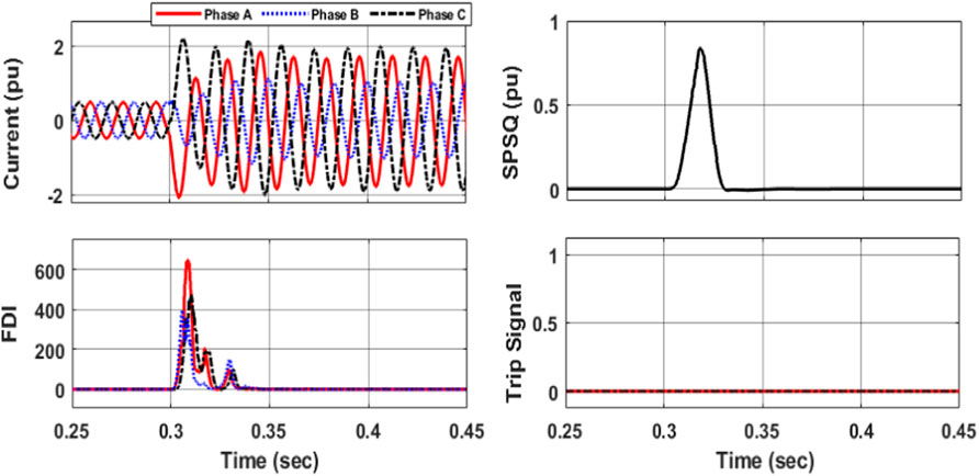
Figure 7. Simulation results obtained at upstream of DL-5 during an ABCG fault at the DL-3.
To evaluate the performance of the proposed method under challenging conditions, simulations were conducted involving the switching of a 2 Mvar capacitor at Bus-4 and a heavy load of 6 MW at Bus-6. The simulation results are depicted in Figure 8 and Figure 9. It is evident from these figures that the proposed scheme did not identify these events as faults. Although the current waveform has significant variations during these events, the FDI remained well below the threshold for both the cases. Additionally, the SPSQ exhibited a very small negative value, which was also significantly lower than the threshold of 0.1.
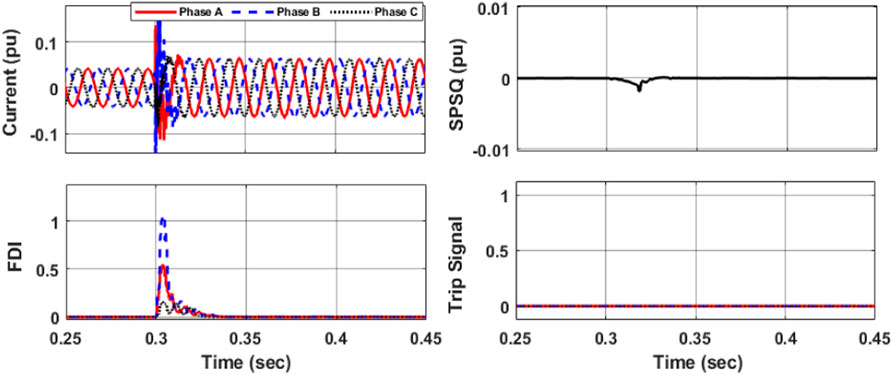
Figure 8. Simulation results obtained at upstream of DL-4 during a 1.2 Mvar capacitor switching event at Bus-4 in grid-connected mode.
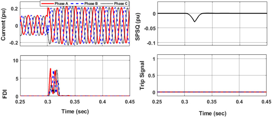
Figure 9. Simulation results obtained at upstream of DL-5 during a 6 MW Load increment event at Bus-6 in grid-connected mode.
In summary, the proposed protection method is capable of accurately differentiate between normal and faulty events in the MGs. Moreover, the proposed scheme is also able to classify and locate the faults in the looped and radially configured microgrids during the grid-connected mode.
4.2 Islanded mode
In islanded mode, the MG experiences fewer transients compared to grid-connected mode as there is no contribution from the utility grid to fault currents, and DERs can only provide 2 to 3 times the rated current. To test the effectiveness of the proposed protection scheme in islanded mode, various simulations were conducted by simulating all short-circuit faults on each distribution line of the test MG.
The simulation results attained during a solid AG fault at DL-5 of the test MG in islanded mode are presented in Figure 10. The proposed FDI successfully detected the fault within a cycle, indicating the effectiveness of the scheme in islanded mode. The FDIs of phase A and phase B were less than the threshold, whereas the FDI of phase C, the faulty phase, exceeded the threshold. This verifies the ability of the proposed scheme to accurately detect and classify single-phase-to-ground faults in islanded mode. Moreover, the negative value of the SPSQ confirmed the effective operation of the fault direction unit.
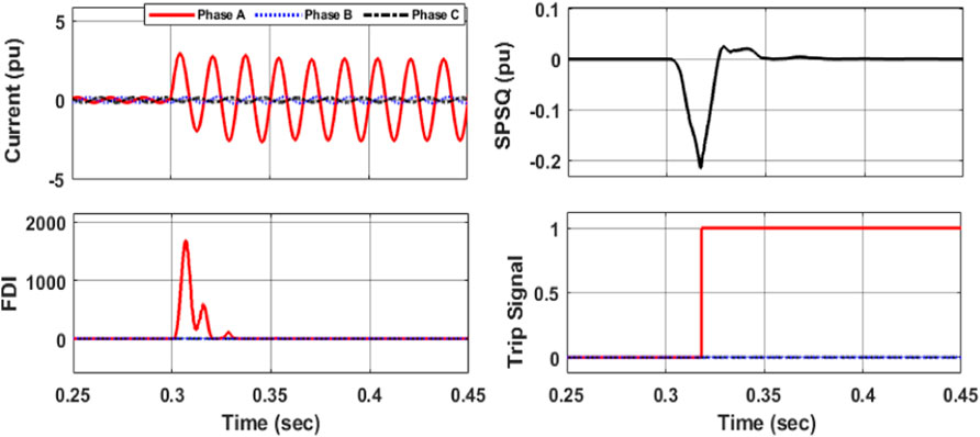
Figure 10. Simulation results obtained at upstream of DL-4 during an AG fault in islanded mode.
Similarly, simulations were conducted for the double phase-to-ground faults on DL-3 in islanded mode and the results are presented in Figure 11. It is evident from the figure that the FDI of the faulty phases exceeded the predefined threshold, whereas the FDI of phase-A, which represents the healthy phase, remained below the threshold. Moreover, the negative SPSQ value indicated that the fault is a forward fault for the relay.
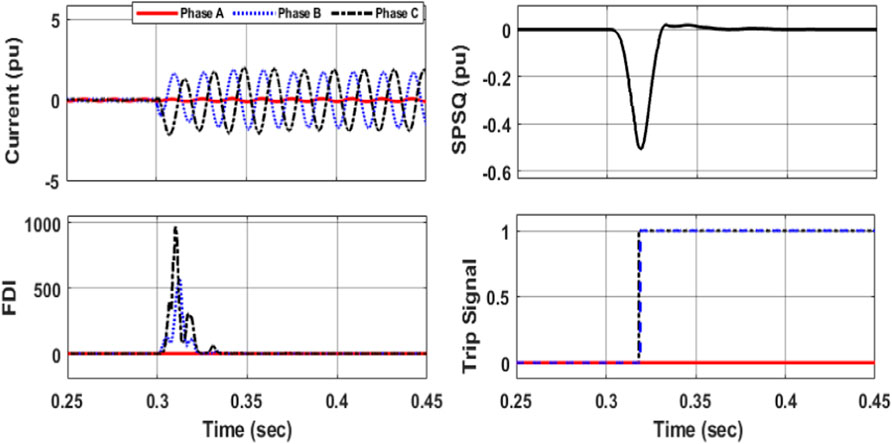
Figure 11. Simulation results obtained at upstream of DL-3 during an BCG fault in islanded mode.
To authenticate the performance of the presented method in radial configuration during the islanded mode, a symmetrical fault at DL-3 of the IEC MG was simulated. The radial configuration was achieved by opening the CB-1 and CB-2 of the test microgrid. The results for the fault are presented in Figure 12. The results illustrate that the proposed scheme operated successfully for the fault in a radial configuration.
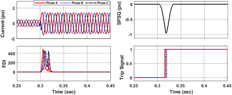
Figure 12. Simulation results obtained at upstream of DL-3 during a three phase fault in radial configuration during islanded mode.
To assess the effectiveness of the proposed method under challenging normal conditions, simulations were executed involving the switching of a 1 Mvar capacitor and the activation of a heavy 3 MW load at Bus-2. The simulation results are shown in Figures 13, 14. It is evident from the figures that the proposed scheme did not consider these events as faults. Although the current waveform has significant variations during these events, the FDI remained well below the threshold for both the cases. The SPSQ has a very small negative value which is also very much less than the threshold of 0.1. This verifies the effectiveness of the proposed scheme is islanded mode of operation.
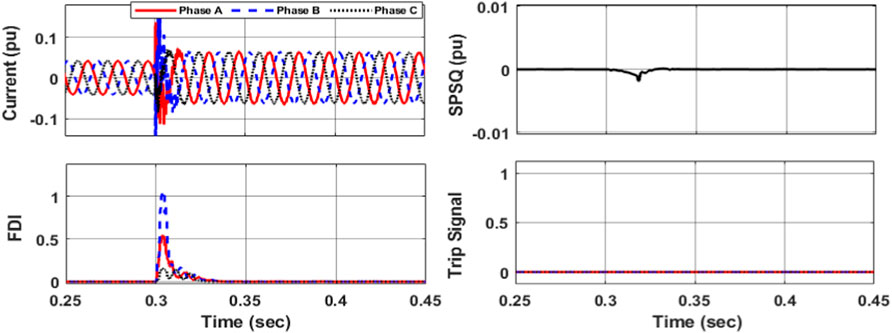
Figure 13. Simulation results obtained at upstream of DL-2 during a 1 Mvar capacitor switching event at Bus-2 in islanded mode.
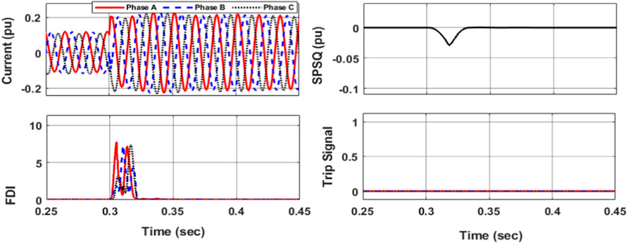
Figure 14. Simulation results obtained at upstream of DL-2 during a 4 MW Load increment event at Bus-2 in islanded mode.
To test the capability of the presented method during reverse faults in islanded mode, a three-phase fault was simulated at DL-1 of the IEC MG which is a reverse fault for the upstream relay of DL-4. The results obtained at the upstream relay of DL-4 are presented in Figure 15. The relay distinguished the fault successfully as FDIs for all the phases are greater than the threshold value. However, the SPSQ is positive in this case because the fault is a reverse fault for this relay. This verifies the effectiveness of the proposed scheme in case of reverses faults in islanded mode of operation.
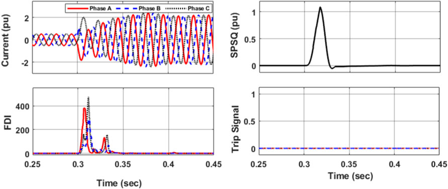
Figure 15. Simulation results obtained at upstream of DL-4 during a three-phase fault at DL-3 in looped configuration during islanded mode.
In summary, the presented protection method can accurately identify, classify, and locate all types of faults in the islanded modes of operation in MGs.
5 Comparison with other schemes
To validate the effectiveness of the proposed protection scheme, a comparison is made with a fuzzy logic-based scheme (Bukhari et al., 2018), a CNN-based protection scheme (Gururani et al., 2016), and a variation mode decomposition (VMD)-based scheme (Dua et al., 2022). The comparison results are shown in Table 3. The Fuzzy Logic-based scheme takes approximately 1.5 cycles for fault detection. It has a medium computational burden and offers backup protection. However, it relies on a communication network and requires expert knowledge in defining fuzzy rules. The CNN-based scheme has a detection time ranging from 1.5 to 2 cycles. It has a very high computational burden and does not provide backup protection. Although it does not rely on a communication network, its implementation is complex and demands a substantial amount of training data. The VMD-based differential protection scheme can detect faults within 2 cycles. It has a high computational burden and requires communication and synchronized measurements. It offers differential protection but necessitates the use of four different threshold values. On the other hand, the proposed protection scheme achieves fault detection within 1.5 cycles and has a low computational burden. It requires minimal communication, provides backup protection, and does not rely on prior data. The scheme only requires a single threshold value. Moreover, the proposed scheme is simple and easy to implement.
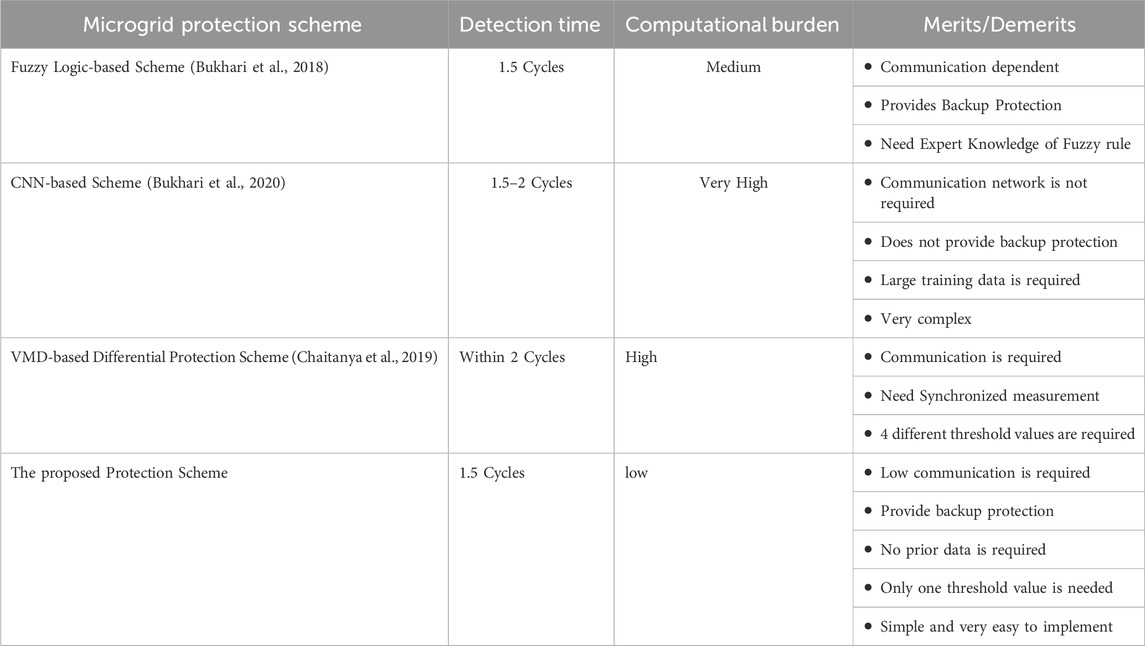
Table 3. Comparison of the proposed scheme with Existing protection methods.
In summary, the comparison table shows that the proposed scheme is superior due to its low communication requirement, provision of backup protection, simplicity of implementation, and the need for only one threshold value.
6 Conclusion
This paper presented a new approach for identifying, classifying and locating the faults in microgrids based on the alienation coefficients and Wigner distribution function. A fault detection index was developed by applying the Wigner distribution function and alienation coefficients on superimposed current components to identify the faulty events in the microgrids. Superimposed positive sequence reactive power was utilized to identify the faulty zone in the microgrid. Several simulations were performed using MATLAB/SIMULINK software to validate the effectiveness of the proposed scheme and it was found that the proposed method was effective in recognizing, classifying, and locating all types of faults in both grid-connected and islanded modes of operation. The proposed protection method is very simple and does not require long calculations and has an easy implementation. The FDI used the same threshold value for both operating modes. The proposed method can protect microgrids (MGs) in all operating modes, in radial and looped configurations, against all types of solid faults. In summary, the proposed methodology has the capability to identify, categorize, and locate various fault types in both grid-connected and islanded modes of operation for both radial and looped microgrids. This will ultimately contribute to the safe and reliable operation of microgrids.
Data availability statement
The original contributions presented in the study are included in the article/supplementary material, further inquiries can be directed to the corresponding authors.
Author contributions
HW: Data curation, Formal Analysis, Investigation, Visualization, Writing–original draft. SB: Formal Analysis, Conceptualization, Resources, Supervision, Writing–review and editing. AW: Conceptualization, Writing–review and editing, Funding acquisition, Methodology, Validation. HA: Funding acquisition, Investigation, Project administration, Supervision, Writing–review and editing. KM: Conceptualization, Data curation, Formal Analysis, Resources, Writing–original draft.
Funding
The author(s) declare that no financial support was received for the research, authorship, and/or publication of this article.
Conflict of interest
The authors declare that the research was conducted in the absence of any commercial or financial relationships that could be construed as a potential conflict of interest.
Publisher’s note
All claims expressed in this article are solely those of the authors and do not necessarily represent those of their affiliated organizations, or those of the publisher, the editors and the reviewers. Any product that may be evaluated in this article, or claim that may be made by its manufacturer, is not guaranteed or endorsed by the publisher.
References
Alam, M. N. (2018). Adaptive protection coordination scheme using numerical directional overcurrent relays. IEEE Trans. Industrial Inf. 15, 64–73. doi:10.1109/tii.2018.2834474
Alam, M. N., Chakrabarti, S., and Pradhan, A. K. (2021). Protection of networked microgrids using relays with multiple setting groups. IEEE Trans. Industrial Inf. 18, 3713–3723. doi:10.1109/tii.2021.3120151
Awagan, G., Koley, E., and Ghosh, S. (2021). “WT and DT-based protection scheme for hybrid microgrid system,” in Proceedings of the 2021 International Conference on Computer System, Information Technology, and Electrical Engineering (COSITE), Banda Aceh, Indonesia, 20-21 October 2021 (IEEE), 41–45.
Bamshad, A., and Ghaffarzadeh, N. (2023). A novel smart overcurrent protection scheme for renewables-dominated distribution feeders based on quadratic-level multi-agent system (Q-MAS). Electr. Eng. 105, 1497–1539. doi:10.1007/s00202-023-01741-6
Brearley, B. J., and Prabu, R. R. (2017). A review on issues and approaches for microgrid protection. Renew. Sustain. Energy Rev. 67, 988–997. doi:10.1016/j.rser.2016.09.047
Bukhari, S. B. A., Haider, R., Zaman, M. S. U., Oh, Y.-S., Cho, G.-J., and Kim, C.-H. (2018). An interval type-2 fuzzy logic based strategy for microgrid protection. Int. J. Electr. Power & Energy Syst. 98, 209–218. doi:10.1016/j.ijepes.2017.11.045
Bukhari, S. B. A., Kim, C.-H., Mehmood, K. K., Haider, R., and Saeed Uz Zaman, M. (2020). Convolutional neural network-based intelligent protection strategy for microgrids. IET Generation, Transm. Distribution 14, 1177–1185. doi:10.1049/iet-gtd.2018.7049
Bukhari, S. B. A., Mehmood, K. K., Wadood, A., and Park, H. (2021). Intelligent islanding detection of microgrids using long short-term memory networks. Energies 14, 5762. doi:10.3390/en14185762
Bukhari, S. B. A., Wadood, A., Khurshaid, T., Mehmood, K. K., Rhee, S. B., and Kim, K.-C. (2022). Empirical wavelet transform-based intelligent protection scheme for microgrids. Energies 15, 7995. doi:10.3390/en15217995
Chaitanya, B. K., Yadav, A., and Pazoki, M. (2019). An improved differential protection scheme for micro-grid using time-frequency transform. Int. J. Electr. Power & Energy Syst. 111, 132–143. doi:10.1016/j.ijepes.2019.04.015
Chauhan, P., Gupta, C. P., and Tripathy, M. (2022). A novel adaptive protection technique based on rate-of-rise of fault current in DC microgrid. Electr. Power Syst. Res. 207, 107832. doi:10.1016/j.epsr.2022.107832
Dehghanpour, E., Karegar, H. K., Kheirollahi, R., and Soleymani, T. (2016). Optimal coordination of directional overcurrent relays in microgrids by using cuckoo-linear optimization algorithm and fault current limiter. IEEE Trans. Smart Grid 9, 1365–1375. doi:10.1109/tsg.2016.2587725
Dua, G. S., Tyagi, B., and Kumar, V. (2022). Microgrid differential protection based on superimposed current angle employing synchrophasors. IEEE Trans. Industrial Inf. 19, 8775–8783. doi:10.1109/tii.2022.3222319
Elkhatib, M. E., and Ellis, A. (2017). “Communication-assisted impedance-based microgrid protection scheme,” in Proceedings of the 2017 IEEE Power & Energy Society General Meeting, Chicago, IL, USA, 16-20 July 2017 (IEEE), 1–5.
Elsadd, M. A., Kawady, T. A., Taalab, A.-M. I., and Elkalashy, N. I. (2021). Adaptive optimum coordination of overcurrent relays for deregulated distribution system considering parallel feeders. Electr. Eng. 103, 1849–1867. doi:10.1007/s00202-020-01187-0
Gadde, P., Brahma, S., and Patel, T. (2022). Real-time hardware-in-the-loop implementation of protection and self-healing of microgrids. IEEE Trans. Industry Appl. 59, 403–411. doi:10.1109/tia.2022.3215624
Ghadiri, S. M. E., and Mazlumi, K. (2020). Adaptive protection scheme for microgrids based on SOM clustering technique. Appl. soft Comput. 88, 106062. doi:10.1016/j.asoc.2020.106062
Gururani, A., Mohanty, S. R., and Mohanta, J. C. (2016). Microgrid protection using hilbert–huang transform based-differential scheme. IET Generation, Transm. Distribution 10, 3707–3716. doi:10.1049/iet-gtd.2015.1563
Heidary, A., Radmanesh, H., Rouzbehi, K., and CheshmehBeigi, H. M. (2020). A multifunction high-temperature superconductive power flow controller and fault current limiter. IEEE Trans. Appl. Supercond. 30, 1–8. doi:10.1109/tasc.2020.2966685
Jain, R., Lubkeman, D. L., and Lukic, S. M. (2018). Dynamic adaptive protection for distribution systems in grid-connected and islanded modes. IEEE Trans. Power Deliv. 34, 281–289. doi:10.1109/tpwrd.2018.2884705
Kulshrestha, A., Mahela, O. P., Gupta, M. K., Gupta, N., Patel, N., Senjyu, T., et al. (2020). A hybrid fault recognition algorithm using Stockwell transform and wigner distribution function for power system network with solar energy penetration. Energies 13, 3519. doi:10.3390/en13143519
Langarizadeh, A., and Hasheminejad, S. (2022). A new differential algorithm based on S-transform for the micro-grid protection. Electr. Power Syst. Res. 202, 107590. doi:10.1016/j.epsr.2021.107590
Nsengiyaremye, J., Pal, B. C., and Begovic, M. M. (2019). Microgrid protection using low-cost communication systems. IEEE Trans. Power Deliv. 35, 2011–2020. doi:10.1109/tpwrd.2019.2959247
Ola, S. R., Saraswat, A., Goyal, S. K., Jhajharia, S. K., Rathore, B., and Mahela, O. P. (2020). Wigner distribution function and alienation coefficient-based transmission line protection scheme. IET Generation, Transm. Distribution 14, 1842–1853. doi:10.1049/iet-gtd.2019.1414
Peng, N., Zhou, L., Liang, R., and Xu, H. (2019). Fault location of transmission lines connecting with short branches based on polarity and arrival time of asynchronously recorded traveling waves. Electr. Power Syst. Res. 169, 184–194. doi:10.1016/j.epsr.2018.12.022
Qusayer, A. F., and Hussain, S. S. (2024). Communication assisted protection scheme based on artificial neural networks for multi-microgrid. IEEE Access 12, 24442–24452. doi:10.1109/access.2024.3352027
Ram Ola, S., Saraswat, A., Goyal, S. K., Sharma, V., Khan, B., Mahela, O. P., et al. (2020). Alienation coefficient and wigner distribution function based protection scheme for hybrid power system network with renewable energy penetration. Energies 13, 1120. doi:10.3390/en13051120
Sadeghi, M., and Abasi, M. (2021). Optimal placement and sizing of hybrid superconducting fault current limiter for protection coordination restoration of the distribution networks in the presence of simultaneous distributed generation. Electr. Power Syst. Res. 201, 107541. doi:10.1016/j.epsr.2021.107541
Saleh, K., Allam, M. A., and Mehrizi-Sani, A. (2020). Protection of inverter-based islanded microgrids via synthetic harmonic current pattern injection. IEEE Trans. Power Deliv. 36, 2434–2445. doi:10.1109/tpwrd.2020.2994558
Sharma, N. K., and Samantaray, S. R. (2019). PMU assisted integrated impedance angle-based microgrid protection scheme. IEEE Trans. Power Deliv. 35, 183–193. doi:10.1109/tpwrd.2019.2925887
Tsimtsios, A. M., Korres, G. N., and Nikolaidis, V. C. (2019). A pilot-based distance protection scheme for meshed distribution systems with distributed generation. Int. J. Electr. Power & Energy Syst. 105, 454–469. doi:10.1016/j.ijepes.2018.08.022
Yin, Y., Fu, Y., Zhang, Z., and Zamani, A. (2021). Protection of microgrid interconnection lines using distance relay with residual voltage compensations. IEEE Trans. Power Deliv. 37, 486–495. doi:10.1109/tpwrd.2021.3063684
Keywords: alienation coefficient, fault detection, fault location, microgrid protection, Wigner distribution function
Citation: Waqar H, Bukhari SBA, Wadood A, Albalawi H and Mehmood KK (2024) Fault identification, classification, and localization in microgrids using superimposed components and Wigner distribution function. Front. Energy Res. 12:1379475. doi: 10.3389/fenrg.2024.1379475
Received: 31 January 2024; Accepted: 07 March 2024;
Published: 20 March 2024.
Edited by:
Amjad Ali, King Fahd University of Petroleum and Minerals, Saudi ArabiaReviewed by:
Ammad Uddin, Institut National des Technologies Avancées de Bretagne (ENSTA Bretagne), FranceImran Baig, Cardiff Metropolitan University, United Kingdom
Copyright © 2024 Waqar, Bukhari, Wadood, Albalawi and Mehmood. This is an open-access article distributed under the terms of the Creative Commons Attribution License (CC BY). The use, distribution or reproduction in other forums is permitted, provided the original author(s) and the copyright owner(s) are credited and that the original publication in this journal is cited, in accordance with accepted academic practice. No use, distribution or reproduction is permitted which does not comply with these terms.
*Correspondence: Syed Basit Ali Bukhari, YmFzaXQuYnVraGFyaUBhamt1LmVkdS5waw==; Hani Albalawi, aGFsYmFsYUB1dC5lZHUuc2E=