 Xiaodong Yin
 Jicheng Yu1*
 Wangwang Ding
- 1China Electric Power Research Institute, Beijing, China
- 2College of Electrical and Information Engineering, Hunan University, Changsha, China
In the context of the rising prevalence of renewable energy, the need for precise and synchronized measurements in urban distribution networks has become increasingly critical. Conventional synchronization techniques, which predominantly depend on Global Navigation Satellite System (GNSS) timing signals, are often plagued by significant sampling time errors. Addressing this challenge, this study introduces an innovative automatic synchronization measurement method employing proportional-integral (PI) control. This method is composed of three integral components: the monitoring of local clock phases via pulses per second (PPS) signals, modulation of the clock phase through a PI controller, and the estimation of grid phasors from the synchronized sampled data. The test results of this method on a hardware platform demonstrate its capability to significantly reduce the sampling error from 2 × 10⁻³ V to an impressive 1 × 10⁻⁵ V, while also meeting the requirements of the synchronized phasor measurement standards outlined in C37.118.1. These advancements underscore the significant potential of PI-controlled simultaneous sampling in enhancing the operational efficiency and reliability of urban distribution networks, particularly in environments with a high integration of renewable energy sources.
1 Introduction
As the continuous development and increasing complexity of the power system [Xiao et al. (2023), Xiao et al. (2023)], as well as the impact on the urban distribution network caused by the access of new energy vehicles and so on Sun et al. (2022), Qiu et al. (2023), the demand for real-time monitoring and accurate estimation of the state of the power grid is also increasing. Synchronized phasor measurement is a critical technique in the power grid sector, providing a framework for data collection across various locations under a unified time index (Phadke et al., 2018; IEEE, 1998). This method plays a pivotal role in enhancing situational awareness within power grids (Phadke, 1993), pinpointing faults accurately (Umunnakwe et al., 2023; Wang et al., 2017), and monitoring oscillations effectively (Singh et al., 2015). The core of synchronized phasor measurement lies in aligning the sampling clocks of analog-to-digital converters (ADCs) to a common time reference (Yao et al., 2018), such as the pulse per second (PPS) signals sourced from GPS or BeiDou satellites (Zhu et al., 2016; Costa et al., 2023). This synchronization ensures that data from each device is captured simultaneously, maintaining the integrity and reliability of the data collected (Lee et al., 2018; Jin et al., 2015).
Specifically, the Analog-to-Digital Converter (ADC) triggered by the local oscillator is reset at each rising edge of the Pulse Per Second (PPS) signal to achieve synchronization once every second (AbdelRaheem et al., 2022; Pardo-Zamora et al., 2021; Monteiro et al., 2016). However, discrepancies between the PPS signal and the local oscillator’s clock domain may result in variations in the actual sampling interval compared to the ideal interval, leading to what is known as Sampling Time Error (STE) (Yao et al., 2018; AbdelRaheem et al., 2022), as illustrated in Figure 1. In other words, STE accumulates over the course of a second and could potentially impair the performance of applications that rely on synchronized sampling data (Maharjan et al., 2015; Joglekar et al., 2021).
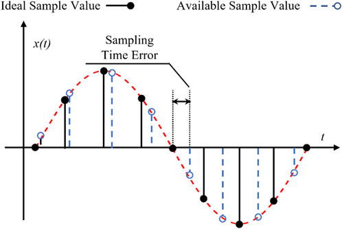
FIGURE 1. Sampling time error diagram.
To tackle the challenge of Sampling Time Error (STE) accumulation, the Variable Sampling Interval with Operating Frequency Monitoring (VSI-OFM) approach, as proposed in a seminal study, presents a groundbreaking strategy (Yao et al., 2018). This method involves dynamically adjusting each sampling interval by the ADC, effectively addressing issues such as the “sawtooth” pattern in phase angle errors and reducing DC offsets and spikes in frequency errors attributed to STEs. Notably, the VSI-OFM technique has been successfully integrated into universal grid analyzers (UGAs), representing the forefront of grid monitoring technology. However, a drawback of this method lies in its direct interaction with the ADC, complicating the sampling process and constraining its application range.
Another promising avenue for mitigating STE accumulation involves utilizing more stable clock sources. A significant breakthrough, as highlighted in a specific study, entails replacing conventional quartz oscillators with chip-scale atomic clocks (CSACs) (Zhan et al., 2016), (Yao et al., 2019). CSACs offer significantly higher frequency accuracy compared to quartz oscillators, boasting accuracy levels up to 0.05 parts per billion, a substantial improvement over the approximately 25 parts per million accuracy of quartz oscillators. Additionally, an alternative approach involves employing double-oven controlled oscillators (DOCOs) instead of CSACs. While these highly precise time-source methods prove effective in curtailing STE accumulation, they also introduce complexities in design and increase maintenance costs, presenting a trade-off between precision and practicality.
In the realm of addressing sampling rate disparities between measurement devices and the IEC 61850-9-2 protocol, an innovative approach was introduced in a particular study (Yamada et al., 2012). This approach integrates two time-domain-based resampling techniques: Real-Time B-Spline Interpolation (RT-BSI) and Modified Akima Piecewise Cubic Hermite Interpolation (MA-PCHI). These methods recalibrate the sampling points by assessing the signal’s local properties and applying interpolation techniques, effectively mitigating Sampling Time Error (STE) (Yang et al., 2018), (Pocola et al., 2021), (Wang et al., 2012). However, it is crucial to note that time-domain manipulations may potentially alter the signal’s frequency domain properties, leading to distortions or added noise, necessitating further research to fully understand the implications of these resampling techniques on synchronized sampling.
Concurrently, frequency-domain based resampling techniques such as polyphase interpolation filter banks and Farrow filters have become prominent in the field of multirate signal processing. These techniques, through sophisticated interpolation or decimation processes, are designed to maintain the signal’s original spectral attributes. In a specific case study, Farrow filters were integrated into a wide-frequency measurement device to facilitate synchronized sampling (Zhou, 2006; Harris, 1997; Harris, 2022). However, this method demands substantial computational resources, leading to increased power consumption in the devices. Such a requirement for high computational capacity can be a significant limitation, particularly for chips with lower processing capabilities, where these techniques may not perform optimally.
In response to the aforementioned challenges, this paper introduces an innovative synchronized sampling and measurement method based on Proportional-Integral (PI) control. The contributions of this work can be summarized as follows:
1) Design of a Sampling PI Controller: A novel sampling PI controller has been developed, specifically tailored for synchronous measurement applications in urban distribution networks. Unlike previous approaches, this method eliminates the need for additional controls on the Analog-to-Digital Converter (ADC) to mitigate Sampling Time Error (STE). This simplification streamlines the sampling process and reduces complexity.
2) Validation Through Simulation and Hardware Verification: The effectiveness of the proposed PI control-based synchronous sampling scheme, as well as the developed hardware equipment, has been rigorously validated through a series of simulation experiments conducted in accordance with the IEEE C37.118.1 standard.
The structure of the remaining sections in this paper is as follows: Section 2 presents the theoretical foundation and principles of the PI control-based synchronous sampling scheme. Simulation and hardware verification results are presented in Section 3 and Section 4, respectively. Finally, the conclusions and implications of this research are summarized in Section 5.
2 Improving sampling accuracy through PI-controlled adjustment of local frequency
This section details a method that utilizes a Proportional-Integral (PI) controller to adjust the frequency of a local Numerically Controlled Oscillator (NCO) for optimizing sampling accuracy. This method uses the phase error between the GNSS PPS signal and the local clock signal to achieve clock calibration. The system receives satellite and local clock signals and compares their phase differences, which reflects the clock error. PI control logic is then used. Proportional control applies a proportional factor based on the error, and integral control considers the cumulative effect of errors to ensure stable and accurate calibration. This method can dynamically adjust the local clock frequency and phase to maintain synchronization with GNSS signals and achieve more accurate sampling. This approach eliminates the need for additional controls on the analog-to-digital converter (ADC) to mitigate sampling time error (STE). This simplification simplifies the sampling process and reduces complexity.
2.1 Phase error detection
Phase error monitoring in this system involves comparing the GNSS’s Pulse Per Second (PPS) signal with the local Numerically-Controlled Oscillator (NCO) clock signal to measure their phase difference. This process can be expressed as follows (Eq. 1).
where
This process determines the synchronization deviation between the two signals, which is the basis for subsequent frequency adjustment. The phase error signal is obtained by calculating this phase difference, where the precise GNSS PPS signal acts as a reference for synchronization against the local NCO signal.
2.2 PI controller design for NCO frequency adjustment
The PI (Proportional-Integral) controller is essential in our method for fine-tuning the frequency of the Numerically-Controlled Oscillator (NCO) in response to phase errors. Its key role is to dynamically adjust the NCO’s frequency to reduce phase discrepancies, thereby aligning more accurately with the GNSS standard. The controller’s output,
Here,
The proportional gain,
The integral gain,
2.3 NCO frequency adjustment mechanism
The output frequency of the Numerically-Controlled Oscillator (NCO) is adjusted based on a calculated control word, typically referred to as the Frequency Control Word (FCW). The relationship governing the output frequency
Here,
The control logic within the NCO takes the desired frequency adjustment output from the PI controller
3 Synchronized phasor estimation method based on recursive DFT
3.1 Basic principle of recursive DFT
The aim of the recursive DFT is to reduce the computational load required to compute the DFT at each sampling point. It is based on the fact that when the signal sequence
Here,
3.2 Synchronized phasor estimation
Based on the results of the recursive DFT, the amplitude, phase and frequency of the signal can be estimated. These three parameters constitute the so-called synchronized phasor.
The amplitude
This equation considers the amplitude normalization factor
The phase angle
The frequency
where
Then, the frequency of the signal can be estimated using the following least squares method formula as follow Eq. 8:
where
4 Experimental validation of PI-controlled synchronization
In this experiment, we aim to assess the effectiveness of our PI-controlled synchronized phasor measurement method in urban distribution networks, focusing on measurement precision. Traditional PPS-based methods, though reliable, may lack the required accuracy for certain applications. Our method, aligning with the IEEE C37.118.1 standard for accuracy and reliability, introduces refined synchronization control. We compared two phasor measurement units: one using traditional PPS synchronization and the other utilizing our PI-controlled approach. Both were tested under identical conditions to simulate various network scenarios. Key performance metrics such as synchronization accuracy, response time, and stability were analyzed to determine the advantages of the PI-controlled method over the traditional approach.
4.1 Sampling time error mitigation
In this test, the nominal sampling rate and the actual sampling rate were set to 1,200 Hz and 1,199.991 Hz, respectively. The test signal was a 50 Hz sine wave with 60 dB white noise. The results are shown in Figure 2.

FIGURE 2. Sampling time error mitigation results.
In traditional sampling methods, Sampling Time Error (STE) accumulates over time, reaching up to 2 × 10⁻³ V, and can only be cleared with the arrival of the next Pulse Per Second (PPS) signal. In contrast, the method discussed herein significantly mitigates the cumulative effect of STE in the sampling data, ensuring it does not exceed 1 × 10⁻⁵ V per second. By comparison, software-based resampling synchronization methods also effectively reduce STE, maintaining it below 2 × 10⁻⁵ V. However, these methods demand substantial computational resources from the core processor, rendering them impractical for operation in small-scale devices when measuring three-phase information simultaneously. This comparison highlights the advantages of the proposed method in reducing STE with greater efficiency and lower computational demand, offering a viable solution for high-precision measurements in constrained environments.
4.2 Frequency offset testing
The frequency offset testing, as mandated by the IEEE C37.118.1 standard, is crucial for assessing the adaptability and accuracy of synchronization algorithms and devices within the context of modern electrical grids. This testing, performed through a signal generator producing signals across a range from 45 Hz to 55 Hz, addresses the increasing frequency fluctuations attributed to the rising integration of renewable energy sources. Such fluctuations pose challenges to grid stability and reliability. The expanded frequency range for testing is essential to ensure that our algorithms and devices can handle the broader variability seen in grids with a high proportion of renewable energy, where traditional stability mechanisms are often stretched to their limits. This testing is therefore vital for applications in contemporary energy networks, which are increasingly characterized by significant renewable energy contributions and the resultant frequency variations.
The results, as depicted in the accompanying Figure 3, clearly demonstrate that devices employing the proposed PI-controlled algorithm consistently met the standard requirement of a Total Vector Error (TVE) less than 1% across all test frequencies. In contrast, devices using the traditional method exhibited a consistently higher TVE, exceeding 1%. This discrepancy is attributed to the cumulative effect of sampling time errors inherent in the traditional approach, underscoring the enhanced accuracy and reliability of the PI-controlled method in handling frequency variations.
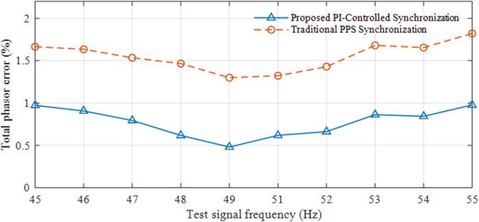
FIGURE 3. Frequency offset testing.
4.3 Amplitude and phase modulation testing
With the continuous increase in the dynamic nature of grid signal, there is a gradual rise in the bandwidth requirements for dynamic measurements. According to the specifications of IEEE C37.118.1 standard, the bandwidth for synchronous phasor measurements should be determined by applying sine amplitude and phase modulation scanning inputs, while ensuring that the Total Vector Error (TVE) does not exceed 3%. The input of the positive sequence signal can be calculated using the Eq. 9.
Here,
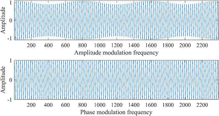
FIGURE 4. Amplitude modulation and phase modulation waveforms.
This study conducts tests on the signal using both traditional methods and PI control, evaluating the measurement errors in frequency and phase angle at different modulation frequencies. The test results, as shown in Figure 5, reveal that at a modulation frequency of 5 Hz, the traditional method exhibits total harmonic distortion (TVE) of 4.38% and 3.23% in amplitude modulation and phase modulation tests, respectively, exceeding the limits specified in the IEEE C37.118.1 standard. In contrast, in both tests, the maximum TVE value with PI control is 2.94%, still complying with the standard requirements. Therefore, the results indicate that the proposed PI control method outperforms traditional methods in this study.
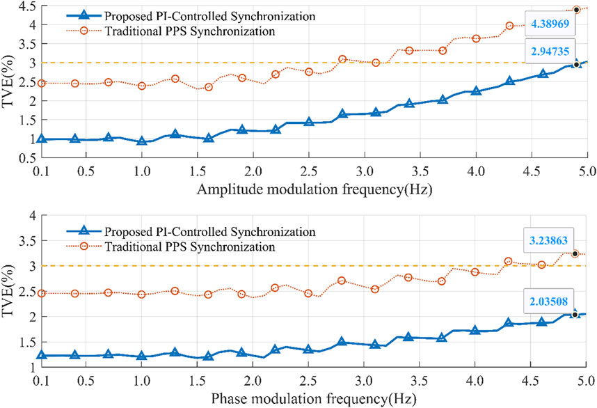
FIGURE 5. Amplitude and phase modulation test results.
4.4 Field testing in the actual power grid
The method introduced was implemented in a Phasor Measurement Unit (PMU) and compared with the most advanced synchronization measurement device in the distribution network side, the Universal Grid Analyzer (UGA). As shown in Figure 6, the testing results for frequency and phase indicate that the precision of the proposed method closely matches that of the UGA, with a frequency relative error of ±0.5 mHz and a phase relative error of 0.05°. This demonstrates the method’s excellent accuracy. Additionally, the proposed method does not require extra computational overhead, making it suitable for scenarios demanding low power consumption or cost control.
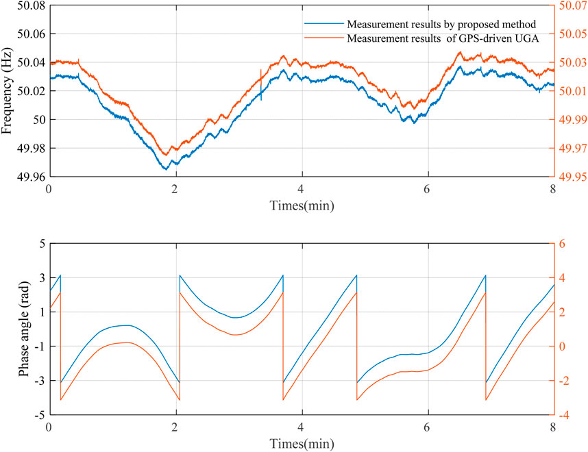
FIGURE 6. Field testing results in the actual power grid.
5 Conclusion
This study presents a novel Proportional-Integral (PI) control-based synchronized sampling method designed for urban distribution networks. The proposed method addresses the inherent limitations of traditional synchronized sampling techniques, particularly in scenarios with high integration of renewable energy sources. Our approach, through its unique combination of local clock phase monitoring, PI controller-based modulation of clock phase, and accurate estimation of grid phasors, effectively reduces the Sampling Time Error (STE).
The experimental results demonstrate a significant reduction in STE, from 2 × 10⁻³ V in traditional methods to an impressive 1 × 10⁻⁵ V using the PI-controlled approach. Furthermore, our method achieves a phase angle measurement accuracy of ±3 × 10⁻⁵ rad, underlining its potential to enhance operational efficiency and reliability in urban distribution networks.
In terms of practical application, this method simplifies the sampling process by eliminating the need for additional controls on the Analog-to-Digital Converter (ADC) and does not rely on external Phase Locked Loop (PLL) blocks, thereby offering a cost-effective solution. The implementation of this method on a hardware platform and its subsequent validation through simulation and hardware testing, in accordance with the IEEE C37.118.1 standard, establishes its viability and effectiveness.
In short, the synchronous sampling method based on PI control provides an unprecedented solution for improving the accuracy and reliability of power grid synchronous measurement. However, it is worth noting that this method still has some challenges and limitations in practical applications. First, implementing PI control in systems with different network configurations or different levels of synchronization requirements may face certain difficulties. Second, the scalability of this approach is limited, especially when dealing with larger or more complex grids. In addition, the PI controller parameters need to be optimized to adapt to different grid conditions, which increases the complexity of implementing PI control. In addition, integrating PI control methods with existing power system infrastructure may face certain challenges, while testing the effectiveness of PI control in larger and more complex networks may be limited by environmental conditions. Therefore, future research will focus on solving these problems, including exploring the application of this method in grid configurations of different sizes and complexities, optimizing PI controller parameters, and solving integration and test environment limitations, etc., to further improve the performance of the power system and manageability.
Data availability statement
The original contributions presented in the study are included in the article/Supplementary material, further inquiries can be directed to the corresponding author.
Author contributions
XY: Formal Analysis, Writing–original draft, Writing–review and editing. JY: Conceptualization, Methodology, Writing–review and editing, Writing–original draft. SL: Software, Validation, Writing–review and editing. JL: Investigation, Resources, Writing–review and editing. JW: Funding acquisition, Supervision, Visualization, Writing–review and editing. CL: Writing–review and editing, Data curation. WD: Methodology, Writing–review and editing.
Funding
The author(s) declare financial support was received for the research, authorship, and/or publication of this article. This work was supported by the State Grid Corporation of China Science and Technology Project under Grant 5700-202319273A-1-1-ZN. (NO. 5700-202319273A-1-1-ZN).
Conflict of interest
The authors declare that the research was conducted in the absence of any commercial or financial relationships that could be construed as a potential conflict of interest.
Publisher’s note
All claims expressed in this article are solely those of the authors and do not necessarily represent those of their affiliated organizations, or those of the publisher, the editors and the reviewers. Any product that may be evaluated in this article, or claim that may be made by its manufacturer, is not guaranteed or endorsed by the publisher.
References
AbdelRaheem, M., Hassan, M., and Selim, H. (2022). A lightweight sampling time error correction technique for micro phasor measurement units. IEEE Trans. Instrum. Meas. 71, 1–8. Art no. 9004408. doi:10.1109/TIM.2022.3179009
Costa, F., Frigo, G., Husmann, D., Jallageas, A., and Morel, J. (2023). “Comparison of time synchronization sources for PMU calibration infrastructures,” in Proceedings of the 2023 IEEE international symposium on precision clock synchronization for measurement, control, and communication (ISPCS) (London, United Kingdom), 1–6. doi:10.1109/ISPCS59528.2023.10297016
Harris, F. (1997). Performance and design of Farrow filter used for arbitrary resampling. Proceedings of the 13th Int. Conf. Digital Signal Process, Santorini, Greece 595–599. doi:10.1109/ICDSP.1997.628420
Harris, F. J. (2022). Multirate signal processing for communication systems. Boca Raton, FL, USA: CRC Press.
IEEE standard for synchrophasor measurements for power systems,” in IEEE Std C37.118.1-2011 (Revision of IEEE Std C37.118-2005). 1–61. doi:10.1109/IEEESTD.2011.6111219
Jin, Z., Zhang, H., and Li, C. (2015). “WAMS light and its deployment in China,” in Proceedings of the 2015 5th international conference on electric utility deregulation and restructuring and power technologies (DRPT) (Changsha, China), 1373–1376. doi:10.1109/DRPT.2015.7432445
Joglekar, A., Gurrala, G., Kumar, P., Joseph, F. C., Kiran, T. S., Sahasranand, K. R., et al. (2021). Open-source heterogeneous constrained edge-computing platform for smart grid measurements. IEEE Trans. Instrum. Meas. 70, 1–12. Art no. 9003612. doi:10.1109/TIM.2021.3078557
Lee, G., Kim, S. H., and Shin, Y.-J. (2018). “Time-synchronized measurements and applications for monitoring of intelligent electric power systems,” in Proceedings of the 2018 IEEE international conference on big data and smart computing (BigComp) (Shanghai, China), 751–755. doi:10.1109/BigComp.2018.00143
Maharjan, S., Peng, J. C. H., and Martinez, J. E. (2015). “Improved off-nominal operation of phasor measurement units using discrete fourier transformation,” in Proceedings of the 2015 IEEE power and energy conference at Illinois (PECI) (Champaign, IL, USA), 1–5. doi:10.1109/PECI.2015.7064887
Monteiro, C. A., Machado, C. L. D. S., and Dalmas, M. (2016). “Global sample synchronization trigger,” in Proceedings of the 2016 IEEE international symposium on precision clock synchronization for measurement, control, and communication (ISPCS) (Stockholm, Sweden), 1–4. doi:10.1109/ISPCS.2016.7579508
Pardo-Zamora, O. N., Romero-Troncoso, R. d. J., Millan-Almaraz, J. R., Morinigo-Sotelo, D., and Osornio-Rios, R. A. (2021). Methodology for power quality measurement synchronization based on GPS pulse-per-second algorithm. IEEE Trans. Instrum. Meas. 70, 1–9. Art no. 1501309. doi:10.1109/TIM.2020.3036691
Phadke, A. G. (1993). Synchronized phasor measurements in power systems. IEEE Comput. Appl. Power 6 (2), 10–15. doi:10.1109/67.207465
Phadke, A. G., Bi, T., and Tech, V. (2018). Phasor measurement units WAMS and their applications in protection and control of power systems. J. Mod. Power Syst. Clean Energy 6 (4), 619–629. Also Power System Grid Operation Using Synchrophasor Technology. Springer, 2018. doi:10.1007/s40565-018-0423-3
Pocola, A. A., Dogaru, E. A., Crisovan, F. I., Frigura-Iliasa, M., Frigura-Iliasa, F. M., and Vatau, D. (2021). “Algorithm for calculating the B-spline coefficients used in interpolations for harmonics assessment in power systems applications,” in Proceedings of the 2021 10th international conference on ENERGY and ENVIRONMENT (CIEM) (Bucharest, Romania), 1–4. doi:10.1109/CIEM52821.2021.9614702
Qiu, W., Yadav, A., You, S., Dong, J., Kuruganti, T., and Liu, Y. (2023). Neural networks-based inverter control: modeling and adaptive optimization for smart distribution networks. IEEE Transactions on Sustainable Energy. IEEE
Singh, M., Allen, A. J., Muljadi, E., Gevorgian, V., Zhang, Y., and Santoso, S. (2015). Interarea oscillation damping controls for wind power plants. IEEE Trans. Sustain. Energy 6 (3), 967–975. doi:10.1109/TSTE.2014.2348491
Sun, K., Qiu, W., Dong, Y., Zhang, C., Yin, H., and Yao, W. (2022). WAMS-based HVDC damping control for cyber attack defense. IEEE Transactions on Power Systems 38702–713. IEEE. doi:10.1109/TSTE.2014.2348491
Umunnakwe, A., Alimi, A., Davis, K. R., and Butler-Purry, K. L. (2023). “Improving situational awareness in power grids of developing countries: a case study of the Nigerian grid,” in Proceedings of the 2023 IEEE power & energy society innovative smart grid technologies conference (ISGT) (Washington, DC, USA), 1–5. doi:10.1109/ISGT51731.2023.10066359
Wang, J., Yang, F., and Du, X. (2012). “Microgrid harmonic and interharmonic analysis algorithm based on cubic spline interpolation signal reconstruction,” in Proceedings of the IEEE PES innovative smart grid technologies (Tianjin), 1–5. doi:10.1109/ISGT-Asia.2012.6303361
Wang, M., Qu, Z., He, X., Li, T., Jin, X., Gao, Z., et al. (2017). “Real time fault monitoring and diagnosis method for power grid monitoring and its application,” in 2017 IEEE conference on energy internet and energy system integration (EI2) (Beijing, China), 1–6. doi:10.1109/EI2.2017.8245672
Xiao, H., Gan, H., Yang, P., Li, L., Li, D., Hao, Q., et al. (2023). Robust submodule fault management in modular multilevel converters with nearest level modulation for uninterrupted power transmission. IEEE Transactions on Power Delivery. 27 (3), 1377–1384. doi:10.1109/TPWRD.2012.2189590
Xiao, H., He, H., Zhang, L., and Liu, T. (2023). Adaptive Grid-Synchronization Based Grid-Forming Control for Voltage Source Converters. IEEE Transactions on Power Systems., 1–4. doi:10.1109/TPWRS.2023.3338967
Yamada, T., Kon, S., Hashimoto, N., Yamaguchi, T., Yazawa, K., Kondo, R., et al. (2012). ECT evaluation by an error measurement system according to IEC 60044-8 and 61850-9-2. IEEE Trans. Power Deliv. 27 (3), 1377–1384. doi:10.1109/TPWRD.2012.2189590
Yang, Z., Liu, H., Bi, T., Yang, Q., and Xue, A. (2018). “An ICSI-based PMU data recovering method,” in Proceedings of the 2018 IEEE power & energy society general meeting (PESGM) (Portland, OR, USA), 1–5. doi:10.1109/PESGM.2018.8586507
Yao, W., Zhan, L., Liu, Y., Till, M. J., Zhao, J., Wu, L., et al. (2018). A novel method for phasor measurement unit sampling time error compensation. IEEE Trans. Smart Grid 9 (2), 1063–1072. doi:10.1109/TSG.2016.2574946
Yao, W., Zhan, L., Yin, H., and Liu, Y. (2019). PMU holdover performance enhancement using double-oven controlled oscillator. IEEE Trans. Power Deliv. 34 (6), 2260–2262. doi:10.1109/tpwrd.2019.2912524
Zhan, L., Liu, Y., Yao, W., Zhao, J., and Liu, Y. (2016). Utilization of chip-scale atomic clock for synchrophasor measurements. IEEE Trans. Power Deliv. 31 (5), 2299–2300. doi:10.1109/tpwrd.2016.2521318
Zhou, D. (2006). Review of polyphase filter banks and their application. Defense Technical Information Center. Fort Belvoir, VG, USA In-House Final Technical Report.
Keywords: proportional-integral control, synchronized sampling, optimizing sampling accuracy, synchronized phasor estimation, urban distribution networks
Citation: Yin X, Yu J, Liang S, Liu J, Wang J, Liu C and Ding W (2024) Synchronized measurement method for urban distribution networks based on proportional-integral control. Front. Energy Res. 12:1378913. doi: 10.3389/fenrg.2024.1378913
Received: 30 January 2024; Accepted: 16 February 2024;
Published: 29 February 2024.
Edited by:
Kaiqi Sun, Shandong University, ChinaReviewed by:
Ying Xue, South China University of Technology, ChinaChengbin Liang, Guizhou University, China
Xianda Deng, Tsinghua University, China
Copyright © 2024 Yin, Yu, Liang, Liu, Wang, Liu and Ding. This is an open-access article distributed under the terms of the Creative Commons Attribution License (CC BY). The use, distribution or reproduction in other forums is permitted, provided the original author(s) and the copyright owner(s) are credited and that the original publication in this journal is cited, in accordance with accepted academic practice. No use, distribution or reproduction is permitted which does not comply with these terms.
*Correspondence: Jicheng Yu, eXVqaWNoZW5nQGVwcmkuc2djYy5jb20uY24=