 Xianwen Bao*
 Lirong Zhang
- School of Aerospace Engineering, Beijing Polytechnic, Beijing, China
Compared to the traditional thermal power generation, new energy sources, such as wind and photovoltaic systems, are more vulnerable to the effects of non-ideal power grids due to their limited capacity. This susceptibility can jeopardize the safe operation of power equipment, degrade power output quality, and lead to non-compliance with grid-connected specifications. The LCL-type grid-connected inverter is a typical nonlinear system that weakens the controllability of the grid-connected energy. To address these challenges, this study employs feedback linearization theory to transform the inverter into a standard linear system. Subsequently, it utilizes linear system methodologies to develop robust control laws, ultimately introducing a multi-functional multiplexing control strategy for grid-connected inverters based on feedback linearization and Hamilton-Jacobi-Issacs inequality. Simulation results demonstrate that this multi-functional strategy outperforms traditional grid-connected inverter control schemes, effectively mitigating issues related to low short-circuit ratios, voltage fluctuations, imbalances, harmonics, and other non-ideal grid conditions. Furthermore, it significantly expands the system’s adaptability to varying weak grid impedances.
1 Introduction
In recent decades, the growing demand for energy and increasing environmental concerns have accelerated the development of renewable energy technologies for power generation (Liu J. et al., 2022; Chen Y. et al., 2023). However, due to factors such as the availability of natural resources and the distribution of power loads, new energy power plants are often situated in remote areas characterized by weak power grids. Consequently, the connected power grid frequently exhibits non-ideal conditions, including voltage drops, imbalances, and harmonic distortions (Liu R. et al., 2022). In contrast to traditional thermal generating units, new energy generation equipment, owing to their limited capacity, is more susceptible to non-linear load variations and unbalanced conditions (Chen et al., 2022; Ding et al., 2022). Instantaneous faults in the power grid can result in rapid voltage reductions that render common control strategies inadequate for meeting grid-connected inverter requirements. This situation threatens the safe operation of the power grid and impacts power output quality and compliance with grid-connected specifications. Moreover, distorted grid currents can exacerbate harmonic pollution in the grid.
Several strategies have been proposed to address these challenges. In (Fu et al., 2021), a double-closed loop control strategy for grid-side current and inductor-capacitor-inductor (LCL) filter capacitor voltage was designed, taking into account impedance variations and system parameter design methods that consider phase-locked loop disturbances. In (Chen J. et al., 2023), model predictive control is used to design the controller using a small signal model, which can ensure stable control in the case of small disturbances, but the output characteristics are not ideal when deviating from the initial operating point (Cai et al., 2021). Introduced a multi-objective optimization function combined with particle swarm optimization (Tran et al., 2021). Developed a robust and optimized grid-free voltage sensor current controller based on active disturbance suppression control is developed for LCL filtered grid-connected inverters in a non-ideal grid (Li et al., 2018; Elamri et al., 2022; Tu et al., 2022). Proposed various control objectives that offer partial adaptability to weak grid conditions but fall short in balancing grid harmonics and providing low-voltage ride-through (LVRT) capabilities. In (Zhou et al., 2024), the predictive current control is equivalently transformed into a voltage function, and the reference voltage is calculated by the current model using a differential-free beat method, and then the optimal voltage vector is obtained based on the principle of suppressing harmonic currents, which is verified under open-circuit and short-circuit faults. An integrated strategy combining model predictive control with wind turbine grid-side converter control is proposed in article in (Abdelkader et al., 2023). The control is realized during grid voltage disturbances and provides reactive power support to the grid. Existing grid-connected inverter control strategies seldom consider both low short-circuit ratio (SCR) and LVRT objectives simultaneously, and current control methods struggle to cope with the complex and constantly changing power grid environment. Consequently, there is a pressing need to develop multi-functional grid-connected inverters capable of achieving stable operation in weak power grid environments while managing power quality through features such as LVRT and harmonic suppression. Such an endeavor holds both theoretical and practical significance. The generalized Hamiltonian system has clear physical meaning and clear system structure, and under certain conditions, the Hamiltonian function can construct the energy-based Lyapunov function of the system, which plays a very important role in the stability analysis and control design of the system. In recent years, the research on the generalized Hamiltonian system has attracted wide attention in the field of nonlinear control, and has been successfully applied in the field of power system (Wu et al., 2022). Due to the strong nonlinearity of the LCL-type grid-connected inverter, in the process of practical controller design, in order to reduce the difficulty of controller design, PI controllers designed based on the approximate linearization model of a single operating state are mostly used, and when the unit operating point deviates from its linearization point, the control performance will be reduced, and even cause the system instability. To solve this problem (Chen et al., 2021), designed a controller with variable gain, which constantly changes the controller gain with the change of the unit operating point, but the controller has a certain impact on the system when switching. Some intelligent control techniques, such as artificial intelligence technology, evolutionary algorithm, swarm intelligence optimization, are difficult to be implemented, although they overcome the requirement of the accuracy of the mathematical model of the control object (Chen et al., 2021).
This paper concentrates on the impact of asymmetric voltage drops and low SCR on the operating state of grid-connected inverters under non-ideal grid conditions. The study explores multi-objective control strategies for grid-connected inverters, aiming to achieve multi-functional multiplexing control in inverters equipped with LCL filters.
LCL-type grid-connected converters offer excellent high-frequency filtering capabilities, with smaller size and lower power loss than L-type filters with equivalent filtering performance (Yuan et al., 2019; Wang et al., 2022). Consequently, they are commonly used in high-power, low-switching-frequency applications. However, while effective at filtering, LCL filters introduce additional system complexity and inherent resonance peaks that can affect control system design and stability. This paper establishes switching and average models for LCL-type inverters under a static coordinate system, followed by obtaining an average model under synchronous rotation coordinates. This model forms the foundation for all subsequent research presented in this paper.
2 Modeling
The topology of the LCL-type three-phase inverter is depicted in Figure 1. To streamline the model derivation process, the equivalent series resistance in the inductor and the damping resistance in the capacitor are neglected in the modeling process. Additionally, this paper assumes that the switching frequency of the grid-connected inverter is significantly higher than the grid frequency. Consequently, during the system modeling, only the fundamental harmonic component is considered, and the influence of high-frequency components is disregarded (Amin and Uddin, 2020).
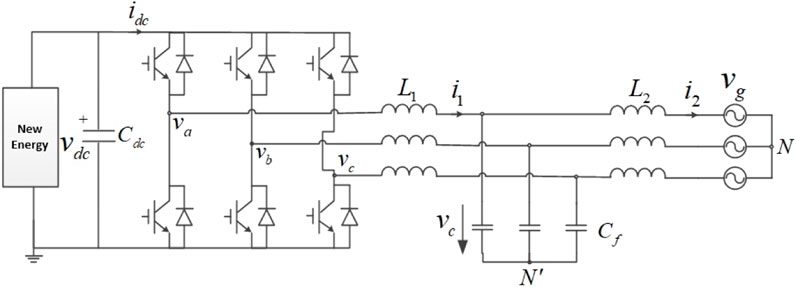
FIGURE 1. Topology of the LCL-type three-phase grid-connected inverter.
2.1 Average model of the three-phase inverter in stationary coordinates
Within the three-phase full-bridge circuit, the insulated-gate bipolar transistor IGBT and reverse diode form a bidirectional two-quadrant switch, which can be effectively modeled as an ideal switch. However, the switch operates discontinuously, making it less conducive for system model derivation and controller design. Referring to the pre-assumptions in the paper, the switching frequency greatly exceeds the system’s fundamental frequency, a sliding average of the on/off states of the IGBT switches during one switching cycle yields an average expression for the switching variables as da, db and dc. Thus, the average model of the LCL-type three-phase grid-connected inverter is derived by the sliding average method, as illustrated in Figure 2. Based on the equivalent circuit of the average model, the differential equations for the system in the static coordinate system has been derived, considering inductance current and capacitance voltage as state variables (Bao et al., 2013).
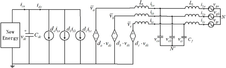
FIGURE 2. Average model of the LCL-type three-phase grid-connected inverter.
Eqs 1–4 represent the differential equations for the three-phase grid-connected inverter with an LCL filter in the static coordinate system.
2.2 Average model of the three-phase inverter in synchronous reference frame
The state variables in the static coordinate system are all alternating current (AC) quantities, which can complicate the design of controllers. Therefore, control strategies for three-phase grid-connected inverters are typically devised in the synchronous rotating coordinate system. To achieve this, the model in stationary coordinates can be transformed into a synchronous reference frame by the transformation matrix T, often called Park’s transformation (Callegaro et al., 2019). This transformation is expressed in Eq. 5:
Its inverse matrix is given in Eq. 6:
This coordinate transformation matrix allows the differential Eqs 1–4 of the inverter in stationary coordinates to be transformed accordingly, shown in Eqs 7–10. It is important to note that there is no neutral wire connection, so the o-channel has been omitted. Subscripts “d” and “q” represent the active and reactive power components, respectively (Liu et al., 2023). dd and dq represent the mean values of the switching variables in synchronous reference frame.
The coordinate transformation converts AC quantities in the physical circuit to their corresponding DC quantities. However, it also introduces six coupling terms between the d-axis and the q-axis. These coupling terms can impact the system’s dynamic response, making it challenging to independently control the D-axis and the Q-axis. Due to the volatility of new energy generation itself and the strong coupling of LCL-type inverters, the two factors are superimposed, increasing the complexity of controller design. The equivalent circuit for the average model of the three-phase grid-connected inverter with an LCL filter in the synchronous reference frame is illustrated in Figure 3.
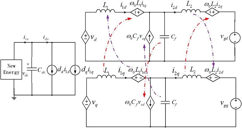
FIGURE 3. Average model of a three-phase LCL grid-connected inverter in a synchronous reference frame.
3 Materials and methods
Many new energy generation systems connect to the end of the power grid, where the SCR is often too low for converters to connect to the grid effectively. It has been shown that when the short-circuit ratio of the AC system is low (SCR
From the modeling results, it is evident that the LCL inverter represents a typical non-linear coupled system. Consequently, traditional proportional-integral (PI) control meets requirements only near the system’s steady-state operating point and fails to ensure stable operation across the entire working range. This limitation severely restricts the grid-connected characteristics of new energy stations, especially in the operating environment of a weak grid. To address this limitation for non-linear systems, this paper introduces a method using Hamilton-Jacobi-Issacs (HJI) inequality. It converts non-linear robust control from engineering applications into mathematical research and applies it to the control of grid-connected inverters, facilitating low-voltage ride-through under weak grids.
3.1 Hamilton-Jacobi-Issacs inequality and its solution
For a nonlinear control system considering the L2 gain, the system can be represented as:
Where x ∈ Rn, u ∈ Rm, w ∈ Rp denote the state vector, input vector, and interference vector, respectively. f(x), g1(x), g2(x), h(x), k(x) are the vector fields defined in the state space. The nonlinear control problem aims to solve two issues: first, finding a control strategy that makes the system asymptotically stable at the equilibrium point; second, ensuring that when the initial condition is x (0) = 0, this control strategy keeps the L2 gain g2 of the system less than or equal to a specified positive variable γ, as shown in Eq. 12:
The designed control law should be able to suppress disturbances, with the degree of disturbance suppression represented by γ. The optimal robust control strategy is achieved if the minimum γ value is reached. In practical engineering design, aiming for the optimal control law may not always be necessary, but rather to seek feasible or satisfactory solutions. If the given value of γ is too small or smaller than its optimal solution, the nonlinear robust control problem may have no solution.
The key to solving the non-linear robustness problem lies in solving the HJI inequality. However, there has not been an efficient way to solve this non-linear inequality. This paper adopts a robust control theory based on the accurate linearization of state feedback for basic linear systems, providing a method to solve the HJI inequality.
The problem of non-linear robust control for a system represented by Eq. 11 involves finding a sufficiently small γ* > 0 and a control strategy u = u*(x) that satisfies the condition for all ∀γ > γ*, as shown in Eq. 13:
This condition ensures the closed-loop system is asymptotically stable when disturbances are absent.
3.2 Design of the grid-connected inverter controller
Building upon the model of the grid-connected inverter, the control variables vd and vq represent the inverter voltages, the output variables i2d and i2q represent the output currents of the inverter, and the disturbance signals vgd and vgq represent the grid voltage. The modeling result Eqs 7–9 can be rewritten as follows:
Where.
Before linearizing the original system, the concept of vector relative order is stated. Relative degree is a measure of the correlation between the inputs and outputs of a system. The relative degree of a real physical system reflects the number of smallest integrators from the control inputs to the outputs of the system, which is determined by the properties of the physical system itself, independent of the way the model is expressed. If a system has vector relative degree
To determine the system’s vector relative order, follow these steps follows Busada et al. (2023); Fang et al. (2023):
(1) h1(x) = i2d
When k = 0,
When k = 1,
When k = 2,
When
(2) h1(x) = i2q
When k = 0,
When k = 1,
When k = 2,
When
From the previous derivation, it is evident that the vector relative order of the LCL-type three-phase grid-connected inverter is
Let us introduce the following Eq. 15 coordinate transformation:
With this coordinate transformation, the linearized system derived from the original system (Eq. 14) is as follows:
When
Where
For (Eq. 17), the robust control law is designed based on the theory of H∞ linear systems. When γ = 3, the Riccati inequality is shown in Eq. 18:
Using MATLAB/LMI Toolbox to solve this equation yields the matrix P*, from which the control law v* of the linear system can be obtained as follows:
The non-linear robust control law for the original system is then as follows:
This control strategy enables the grid-connected inverter to maintain stable operation even in the presence of non-ideal grid conditions.
4 Results and discussion
SCR is a crucial parameter for measuring the strength of the power grid, reflecting the system’s stability margin. It is simple to calculate and has a clear physical meaning, providing a straightforward and intuitive method for analyzing the stability of new energy grid-connected systems. As the proportion of new energy sources in the power grid increases, the SCR of the power grid gradually decreases, indicating a weakening power grid. In order to verify the effectiveness of the algorithm in this paper, simulation is carried out in Simulink platform. Simulation parameters: rated power of 250 kW, grid line voltage of 380 V, frequency of 50 Hz kW, DC bus reference voltage of 550 V, inverter-side inductance of 0.35 mH, inverter-side resistance of 0.1Ω, filter capacitance of 150μF, grid-side resistance of 0.1Ω, grid-side inductance of 0.05 mH, and DC-side capacitance of 6.6 mF. This paper begins by considering different SCRs of the power grid and designs comparative operating conditions, ranging from a strong to a weak power grid. It evaluates the effectiveness of the new MMCS proposed in this paper compared to the PICS.
4.1 Simulation results of traditional PI control strategy
The traditional PI control strategy in the simulation model is employed to test various scenarios under weak power system conditions (SCR = 4.7). These scenarios include steady-state operation, single-phase short-circuit fault, two-phase short-circuit fault, and three-phase short-circuit fault, focusing on LVRT characteristics, power quality, and low voltage crossing characteristics under different conditions.
(1) SCR = 4.7, stable operation
With the PICS approach, when the SCR of the power grid is 4.7, the grid-connected inverter maintains stable operation. However, the voltage and current at the node experience some distortion. Fourier analysis reveals a voltage harmonic (THDu) of 2.80% and a current harmonic (THDi) of 4.71%, approaching the 5% harmonic upper limit for new energy stations connected to the grid. As the grid structure weakens further, the new energy station may not be allowed to connect to the grid.
(2) SCR = 4.7, LVRT test
Under the PICS control strategy, the grid-connected inverter operates stably. When the power grid experiences an instantaneous short-circuit fault, the corresponding LVRT process is examined, as shown in Figure 4.
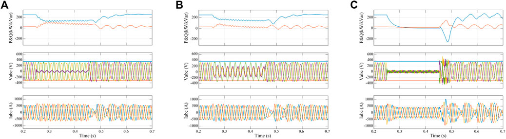
FIGURE 4. Simulation results for different grid faults using the PICS approach (SCR = 4.7). (A) Single-phase short-circuit fault. (B) Two-phase short-circuit fault. (C) Three-phase short-circuit fault.
The simulation results show that under a weak grid condition (SCR = 4.7), the traditional control strategy can maintain steady-state operation. However, the grid voltage and current harmonics increase further. When single-phase and two-phase short-circuit faults occur in the grid, the system can eventually recover to normal after a prolonged period, but the LVRT capability is barely met. In the case of a three-phase short-circuit fault in the power grid, the inverter exhibits post-fault oscillations and cannot return to stability, resulting in a failed LVRT test.
4.2 Simulation results of the multi-functional multiplexing control strategy (MMCS)
The simulation results from the traditional control strategy demonstrate that traditional methods fall short of meeting power grid requirements as the grid weakens. The control effect is tested using the MMCS approach under the simulated SCR = 4.7 conditions to provide a comparative study.
(1) SCR = 4.7, stable operation
The steady-state output characteristics of grid-connected inverters under the MMCS approach are tested. These characteristics demonstrate that the new control strategy significantly outperforms the traditional one. The harmonic content of voltage (THDu) is 1.82%, and current (THDi) is 0.19%, meeting the grid-connected standards for new energy plants.
(2) SCR = 4.7, LVRT test
Under the traditional control strategy, when SCR = 4.7, the grid-connected inverter fails the LVRT test. In the same working conditions, when the new control strategy is applied, and the power grid experiences an instantaneous short-circuit fault, the corresponding LVRT process test is conducted, as shown in Figure 5.
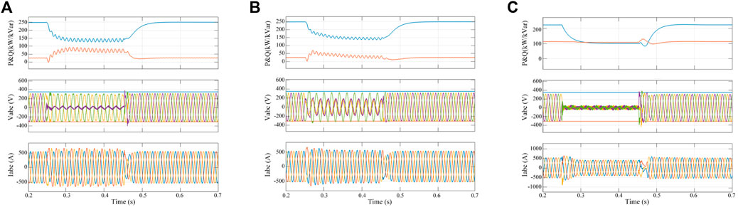
FIGURE 5. Simulation results for different grid faults using the MMCS approach (SCR = 4.7). (A) Single-phase short-circuit fault. (B) Two-phase short-circuit fault. (C) Three-phase short-circuit fault.
The simulation results indicate that the new control strategy successfully passes the different short-circuit faults. Moreover, the grid-connected inverter exhibits a faster recovery time, meeting the grid-connected requirements. Compared with the PICS, it can be demonstrated that the MMCS does not have obvious advantages in the strong grid operation environment (SCR
(3) SCR = 2, stable operation.
To further evaluate the effectiveness of control strategies, the power grid’s short-circuit ratio is further reduced to SCR = 2. Obviously PICS cannot operate stably under this condition. The steady-state output characteristics of grid-connected inverters under MMCS are depicted in Figure 6.
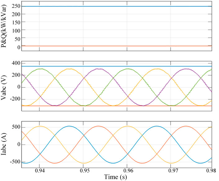
FIGURE 6. Steady-state simulation results of MMCS (SCR = 2).
The simulation results show that even under extremely weak grid conditions (SCR = 2), the grid-connected inverter can operate steadily. The harmonic content of grid-connected voltage (THDu) is 0.2%, and current (THDi) is 1.82%. The state of the grid hardly constrains the output characteristics.
(4) SCR = 2, LVRT test.
When the power grid is extremely weak, the new control strategy is applied to verify whether the grid-connected inverter can operate stably when the power grid experiences an instantaneous short-circuit fault. The corresponding voltage crossing process test is depicted in Figure 7.
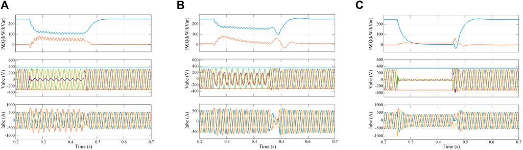
FIGURE 7. Simulation results for different grid faults using MMCS (SCR = 2). (A) Single-phase short-circuit fault. (B) Two-phase short-circuit fault. (C) Three-phase short-circuit fault.
The simulation results indicate that During the single-phase short-circuit fault and the two-phase short-circuit fault, the grid-connected inverter can still operate statically, and there is not much difference between the output characteristics of the weak and strong grids, and both active and reactive power are jittered to a small scale, which is caused by the grid voltage asymmetry fault, and after the fault disappears, the system returns to stable operation within 0.05 s. During the three-phase ground fault, after the fault disappears, the time for the system to restore stability under the weak grid is slightly longer, and the power fluctuation is relatively large at the instant of fault switching, but the overall output characteristics satisfy the technical requirements of the new energy grid-connected low-voltage ride-through. Further reducing the system impedance, the MMCS control strategy also fails to ensure the stable operation of the system at SCR = 1.8.
4.3 Discussion
Comparing the PICS with the MMCS, the traditional PI control strategy, based on a dual closed-loop approach, can ensure stable equipment operation in strong grids. However, as the system’s SCR further decreases, numerous harmonics appear in the grid current. When various voltage faults occur in the power grid, it becomes challenging to swiftly return to a stable state.
In contrast, utilizing feedback linearization control, the multi-functional multiplexing control strategy mitigates the impact of system parameters and power grid disturbances. As SCR decreases, the ability to suppress grid-connected current harmonics significantly improves, effectively enhancing the quality of grid-connected current. The output characteristics of the composite control strategy are more significantly affected by the controller coefficients, while it is insensitive to the steady state operating point. Therefore, with reasonable parameter design, the composite control strategy can achieve accurate synchronization and stable operation under a wide range of operating conditions. It also demonstrates quick and effective recovery in the face of different LVRT faults. This suggests that under the new multi-functional multiplexing control strategy, the dynamic performance of the LCL-type grid-connected inverter is excellent. Consequently, it is more suitable for applications in weak grids.
In summary, the multi-functional multiplexing control strategy offers significant advantages in terms of grid adaptability, harmonic suppression, and LVRT performance, making it a promising choice for addressing the challenges posed by new energy grid-connected systems in weak grid environments. In practical engineering application scenarios, the detection circuit has measurement errors, and the external environment and device aging can cause fluctuations in the parameters of inductance and capacitance. In addition, the performance of the controller and the accuracy of the sensors affect the output effect of the controller, and increase the hardware cost of the system. By analyzing the state equation of the LCL type grid-connected inverter, the system is energetic, so the state observer can also be designed to inhibit the fluctuation of the system parameters and reduce the hardware cost.
5 Conclusion
Grid-connected inverter represent a typical nonlinear system. In this paper, a multi-functional multiplexing control strategy based on precise linearization of state feedback has been proposed. By directly constructing an energy function according to the system model and designing the control law on this foundation, the MMCS avoids the direct solution of the HJI inequality. This approach considers voltage drop and grid harmonics external interference signals. An appropriate evaluation function is defined to transform the control problem into a state feedback law, rendering the closed-loop system asymptotically stable over a wide range when the interference signals are zero. The new control strategy exhibits superior dynamic performance and optimal interference suppression. This paper has verified the algorithm’s effectiveness under different types of grid faults in weak and strong grids, respectively. The results indicate that the new control strategy excels in adapting to weak power grids, offering characteristics such as minimal harmonics, a broad stability range, and rapid system fault recovery. Consequently, it meets the requirements of new energy stations operating in weak power networks.
In conclusion, the proposed robust control strategy holds promise for enhancing the performance and adaptability of grid-connected inverters in non-ideal grid conditions, contributing to the successful integration of new energy sources into power grids.
Data availability statement
The original contributions presented in the study are included in the article/Supplementary material, further inquiries can be directed to the corresponding author.
Author contributions
XB: Formal Analysis, Funding acquisition, Methodology, Validation, Writing–review and editing. LZ: Data curation, Writing–original draft.
Funding
The author(s) declare financial support was received for the research, authorship, and/or publication of this article. This research was funded by R&D Program of Beijing Municipal Education Commission grant number KM202210858002.
Conflict of interest
The authors declare that the research was conducted in the absence of any commercial or financial relationships that could be construed as a potential conflict of interest.
Publisher’s note
All claims expressed in this article are solely those of the authors and do not necessarily represent those of their affiliated organizations, or those of the publisher, the editors and the reviewers. Any product that may be evaluated in this article, or claim that may be made by its manufacturer, is not guaranteed or endorsed by the publisher.
Abbreviations
SCR, short-circuit ratio; LVRT, low voltage ride through; HJI, Hamilton-Jacobi-Issacs inequality; PICS, proportional-integral control strategy; MMCS, multi-functional multiplexing control strategy.
References
Abdelkader, S. M., Morgan, E. F., Megahed, T. F., Wesam, R., and Omar, A.-R. (2023). A model predictive control strategy for enhancing fault ride through in pmsg wind turbines using smes and improved gsc control. Front. Energy Res. 11. doi:10.3389/fenrg.2023.1277954
Amin, I. K., and Uddin, M. N. (2020). Nonlinear control operation of dfig-based wecs incorporated with machine loss reduction scheme. IEEE Trans. Power Electron. 35, 7031–7044. doi:10.1109/tpel.2019.2955021
Bao, X., Zhuo, F., Tian, Y., and Tan, P. (2013). Simplified feedback linearization control of three-phase photovoltaic inverter with an lcl filter. IEEE Trans. Power Electron. 28, 2739–2752. doi:10.1109/tpel.2012.2225076
Busada, C. A., Jorge, S. G., and Solsona, J. A. (2023). Feedback linearization of a grid-tied synchronverter. IEEE Trans. Industrial Electron. 70, 147–154. doi:10.1109/tie.2022.3148747
Cai, Y., He, Y., Zhou, H., and Liu, J. (2021). Design method of lcl filter for grid-connected inverter based on particle swarm optimization and screening method. IEEE Trans. Power Electron. 36, 10097–10113. doi:10.1109/tpel.2021.3064701
Callegaro, L., Ciobotaru, M., Pagano, D. J., and Fletcher, J. E. (2019). Feedback linearization control in photovoltaic module integrated converters. IEEE Trans. Power Electron. 34, 6876–6889. doi:10.1109/tpel.2018.2872677
Chen, J., Zhang, Y., Fang, F., and Liu, J. (2023a). Affine-disturbance-feedback-based multi-objective stochastic model predictive control of wind turbine. Proc. CSEE 43, 496–506. doi:10.13334/j.0258-8013.pcsee.221034
Chen, Q., Yang, F., and Wei, C. (2021). A new compensation network structure and parameter determination method with variable constant voltage gain characteristics based on three-coil wpt system. Proc. CSEE 41, 2277–2288. doi:10.13334/j.0258-8013.pcsee.201636
Chen, W., Zhang, Y., Tu, Y., Shen, K., and Liu, J. (2022). Active damping control for lcl filters with inverter-side current feedback only. IEEE Trans. Power Electron. 37, 10065–10069. doi:10.1109/tpel.2022.3159229
Chen, Y., Sangwongwanich, A., Huang, M., Pan, S., Zha, X., and Wang, H. (2023b). Failure risk assessment of grid-connected inverter with parametric uncertainty in LCL filter. IEEE Trans. Power Electron. 38, 9514–9525. doi:10.1109/tpel.2023.3274396
Ding, X., Xue, R., Zheng, T., Kong, F., and Chen, Y. (2022). Robust delay compensation strategy for lcl-type grid-connected inverter in weak grid. IEEE Access 10, 67639–67652. doi:10.1109/access.2022.3176957
Elamri, O., Oukassi, A., Maamar, A. E. T., and El Bahir, L. (2022). Design and simulation of a power system composed of grid-tied five-level inverter with lcl filter. Electronics 26, 17–25. doi:10.53314/els2226017e
Fang, T., Zhang, H., Wu, H., and Zhang, Y. (2023). Robustness enhancement of coping with dual factors for grid-connected inverter in weak grid based on synthesis-admittance- phasor scheme. IEEE Trans. Industrial Electron. 70, 11346–11356. doi:10.1109/tie.2022.3231294
Fu, Z., Zhang, Z., and Dong, Y. (2021). Lcl type three-phase photovoltaic grid-connected inverter under week grid conditions. Taiyangneng Xuebao/Acta Energiae Solaris Sin. 42, 193–199. doi:10.19912/j.0254-0096.tynxb.2018-1215
Li, X., Fang, J., Tang, Y., Wu, X., and Geng, Y. (2018). Capacitor-voltage feedforward with full delay compensation to improve weak grids adaptability of lcl-filtered grid-connected converters for distributed generation systems. IEEE Trans. Power Electron. 33, 749–764. doi:10.1109/tpel.2017.2665483
Liu, J., Sun, X., Ren, B., Song, W., and Wheeler, P. (2022a). Strong adaptability control based on dual-division-summation current control for an lcl-type grid-connected inverter. IEEE Trans. Power Electron. 37, 14157–14172. doi:10.1109/tpel.2022.3188562
Liu, R., Chen, Z., Tang, W., and Zhu, J. (2022b). Control strategy of an lcl type grid-connected inverter with the influence of a phase-locked loop under a weak power grid. Dianli Xit. Baohu yu Kongzhi/Power Syst. Prot. Control 50, 178–187. doi:10.19783/j.cnki.pspc.210569
Liu, X., Ma, X., Zheng, S., Zhou, J., and Chen, Y. (2023). Feedback linearization and robust control for whirl mode with operating point deviation in active magnetic bearings-rotor system. IEEE Trans. Industrial Electron. 70, 7673–7682. doi:10.1109/tie.2022.3210508
Tran, T. V., Kim, K.-H., and Lai, J.-S. (2021). Optimized active disturbance rejection control with resonant extended state observer for grid voltage sensorless lcl-filtered inverter. IEEE Trans. Power Electron. 36, 13317–13331. doi:10.1109/tpel.2021.3082938
Tu, C., Gao, J., Xiao, F., Guo, Q., and Jiang, F. (2022). Stability analysis of the grid-connected inverter considering the asymmetric positive-feedback loops introduced by the pll in weak grids. IEEE Trans. Industrial Electron. 69, 5793–5802. doi:10.1109/tie.2021.3086716
Wang, X., He, Y., Pan, D., Zhang, H., Ma, Y., and Ruan, X. (2022). Harmonic instability of lcl-type grid-connected inverter caused by the pole-zero cancellation: a case study. IEEE Trans. Industrial Electron. 69, 11580–11589. doi:10.1109/tie.2021.3123616
Wu, Z., Hou, L., Cao, B., Hu, X., and Ma, B. (2022). Cooperative control strategy for wind turbines based on Hamilton system under limited input. Proc. CSEE 42, 4884–4895. doi:10.13334/j.0258-8013.pcsee.210647
Yang, J., Liu, K., and Rao, X. (2015). Small signal modeling for vsc-mtdc. Proc. CSEE 35, 4015–4024. doi:10.13334/j.0258-8013.pcsee.2015.16.003
Yuan, H., Li, S., Qi, W., Tan, S.-C., and Hui, S.-Y. R. (2019). On nonlinear control of single-phase converters with active power decoupling function. IEEE Trans. Power Electron. 34, 5903–5915. doi:10.1109/tpel.2018.2868506
Keywords: grid-connected inverter, low short-circuit ratio, non-ideal power grid, feedback linearization theory, multi-functional multiplexing
Citation: Bao X and Zhang L (2024) Enhancing grid-connected inverter performance under non-ideal grid conditions: a multi-functional multiplexing control strategy. Front. Energy Res. 12:1378808. doi: 10.3389/fenrg.2024.1378808
Received: 30 January 2024; Accepted: 20 February 2024;
Published: 05 March 2024.
Edited by:
Yang Yu, Nanjing University of Posts and Telecommunications, ChinaReviewed by:
Zhenxiong Wang, Xi’an Jiaotong University, ChinaXiaokang Liu, Polytechnic University of Milan, Italy
Copyright © 2024 Bao and Zhang. This is an open-access article distributed under the terms of the Creative Commons Attribution License (CC BY). The use, distribution or reproduction in other forums is permitted, provided the original author(s) and the copyright owner(s) are credited and that the original publication in this journal is cited, in accordance with accepted academic practice. No use, distribution or reproduction is permitted which does not comply with these terms.
*Correspondence: Xianwen Bao, YmFveGlhbndlbjA0MDdAMTI2LmNvbQ==