 Xin Dong1
 Haibin Wang2
 Changkun Zhang1
 Wanneng Yu1,3Rongfeng Yang1,3
 Longhai Xiao1,3Weiqiang Liao1,3,4*Chenghan Luo1
- 1School of Marine Engineering, Jimei University, Xiamen, China
- 2Department of Naval Architecture, Ocean and Marine Engineering, University of Strathclyde, Glasgow, United Kingdom
- 3Marine Engineering College and Key Laboratory of Fujian Province Marine and Ocean Engineering, Jimei University, Xiamen, China
- 4Innovation Laboratory for Sciences and Technologies of Energy Materials of Fujian Province, Xiamen, China
In response to the complexity of the Jacobian matrix inversion process in the power flow algorithm for AC/DC microgrids, leading to large memory requirements and susceptibility to convergence issues, a novel power flow algorithm based on an improved unified iteration method for AC/DC microgrids is proposed. Firstly, the fundamental equations of the unified iteration method and the characteristics of DC systems are analyzed. The reactive power correction terms and voltage phase correction differences are removed from the modified equations of the unified iteration method, and result in a reduction in the order of the Jacobian matrix in the power flow algorithm. Subsequently, the improved IEEE 11-node system is subjected to simulation verification to attain precise power flow solutions for hybrid AC/DC microgrids. The theoretical analysis identifies the main influencing parameters of active and reactive power errors and assesses their impact factors. Finally, experimental validation of the improved power flow algorithm is carried out on a physical platform, clarifying the applicability range of the proposed method. The research results indicate that within allowable error margins, the proposed approach reduces the difficulty of Jacobian matrix inversion, resulting in an 80% increase in computational speed compared to the unified iteration method. It is suitable for microgrid systems with short electrical distances and small magnitudes of node voltage amplitudes and phase differences.
1 Introduction
In the context of “carbon peak” and “carbon neutrality,” the penetration of distributed generation technology in the power grid is gradually increasing, and microgrids have become an effective form of utilizing distributed generation technology (Song et al., 2021; Zou et al., 2022). Hybrid AC/DC microgrids, combining the advantages of both AC and DC microgrids, have become an important direction in the development of microgrid technology. However, there exist complex coupling relationships between AC and DC within the system. Therefore, how to systematically analyze AC/DC microgrids and ensure their safe and stable operation has become a focal research area for scholars worldwide (Liu K. et al., 2019; Hameed et al., 2019; Yang et al., 2019).
Power flow analysis, as one of the fundamental tools for microgrid analysis, its mathematical essence involves solving a set of multivariate nonlinear equations through iterative computations to determine parameters such as voltage, phase angle, and power at various nodes (or buses) within the grid. Power flow analysis is employed to ascertain load distribution, voltage stability, line power losses, and flow distribution of components such as generators, transformers, and transmission lines within the power system (Guoqing et al., 2017; Pengfei, 2022), plays a crucial role in microgrid planning, stability calculations, and fault analysis (Bajpai, 2023; Heidary et al., 2023; Huang et al., 2023; Li et al., 2023). Currently, commonly used power flow calculation methods for AC/DC microgrids include the unified iteration method (UIM) and the alternate iteration method (Nejabatkhah et al., 2019; Song et al., 2023). The alternate iteration method separately solves power flow for AC and DC subsystems, providing fast calculation speeds but relatively lower convergence accuracy. On the other hand, the unified iteration method extends the dimension of the Jacobian matrix by introducing DC variables, allowing for the joint solution of variables in AC and DC systems. However, this increases the order of the Jacobian matrix, requiring matrix decomposition in each iteration, thereby adding to the overall computation time (Wang et al., 2018). Therefore, reducing computational complexity and time in the power flow calculation process while ensuring accuracy has become an important aspect of research on power flow calculation in hybrid AC/DC microgrids.
To enhance the efficiency of AC/DC microgrid power flow calculations, related research has primarily focused on improving existing methods. Reference (Liu et al., 2021) proposed a control mode for distributed grids participating in voltage and frequency regulation based on the Newton-Raphson method. On this basis, it introduced a sequential algorithm framework for handling coupling relationships between AC and DC microgrids. Using an improved Newton-Raphson sub-algorithm, it iteratively solved power flow for hybrid AC/DC microgrids. Reference (Ju et al., 2022) presented a fully Distributed Power Flow (DPF) method, transforming nonsmooth constraints into smooth functions. It employed a two-level Augmented Lagrangian Alternating Direction Inexact Newton (ALADIN) method with second-order convergence speed to convert the DPF problem into a distributed step-size optimization problem. By exchanging microgrid boundary information, it achieved accurate power flow results and improved convergence speed and accuracy through the second-level step-size optimization. Reference (Chen et al., 2017) established a steady-state power flow model for a Droop-type distributed power source and AC/DC inverter. It applied a sequence component conversion based on voltage symmetry at the grid connection point and used a sequence current compensation method to decouple the AC subgrid into three-sequence networks, solving them in parallel and further reducing the solution capacity.
While the above literature has improved computational accuracy and speed through enhancements to existing methods, it does not address the impact of DC system characteristics on power flow calculation equations. To address this gap, this paper first comprehensively considers DC system characteristics and proposes an AC/DC microgrid power flow algorithm based on the unified iteration method. This resolves the issues of long computation times and high computational capacity associated with the unified iteration power flow calculation method. Subsequently, through simulation experiments on the IEEE 11-node system, the effectiveness and high computational efficiency of the proposed algorithm are validated. The study identifies the factors and extent of error generation under different conditions. Finally, experimental verification on a 30 kW load and 70 kW load is conducted on the experimental platform, confirming the feasibility of the improved algorithm.
2 The power flow algorithm for AC/DC systems and its improvement
In an AC/DC microgrid, which includes both AC and DC lines, the selection of DC lines leads to variations in system structure and operational modes. Consequently, there are differences in the equivalent models and DC equations.
Taking a two-terminal bipolar DC transmission system as an example, the selected DC line model is systematically modeled (Yang et al., 2021; Zhu et al., 2022), resulting in the equivalent circuit of the DC system as illustrated in Figure 1:
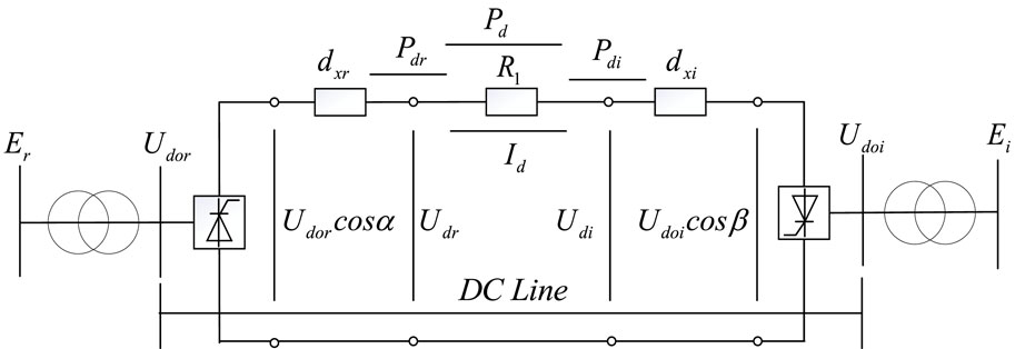
Figure 1. Steady-state model of two-terminal bipolar DC transmission system.
From the equivalent circuit shown in Figure 1, the expressions for the main parameters of the DC line can be obtained as follows:
Eqs 1–3 form the main parameter equations for the two-terminal bipolar DC transmission system.
For a hybrid AC/DC system model with a total of
For a pure AC system with
Where the subscript ‘
The power equations of the UIM are established based on the power equations of the AC system, with the inclusion of DC variables (Peng et al., 2017; Liu K et al., 2019; Lin et al., 2020; Wang et al., 2023). Combining the proposed DC model, the power equation for the hybrid AC/DC system is obtained by introducing DC variables into Eq. 4, as shown in Eq. 6:
Where the positive and negative signs represent the inverter and rectifier, respectively.
Considering the presence of DC variables in the mixed AC/DC system, in Eq. 5, active power and reactive power imbalance terms for the DC nodes, as well as phase difference and voltage difference, are introduced. From Eq. 6, it can be observed that the correction equations introduce new variables
Combining Eqs 1–3, supplement the parameter equation
Rearranging Eq. 3 and forming the parameter equation
The main control equation for the DC system is expressed as Eq. 8:
Where the variables with subscript‘s’ represent the system rated values;
Due to the increase in the quantity to be corrected on the left side of the correction equation, and with only phase difference and voltage difference in the correction discrepancy, it is still not possible to solve the correction equation. Considering the inclusion of Eqs 7, 8 in the quantity to be corrected, and incorporating the characteristic parameters of the DC system, the correction discrepancy for the DC system is expanded by introducing the correction variable
The specific expressions for each variable in
Thus, the correction equation for the UIM in the mixed AC/DC system is:
Among them,
Compared to the Jacobian matrix
In DC lines, the power factor is determined by factors
At the same time, when transmitting electric energy in DC form, due to the special characteristics of DC power supply, there is no induction of reactance in the line during the energy transmission process, and there is no issue of voltage phase angle. For the DC portion in the mixed AC/DC system, there is no need to consider the phase deviation
Eq. 12 represents the expression of the corrected equation after improvement, which is the correction equation of the improved unified iteration method (IUIM).
3 Example verification
3.1 Parameter settings
The standard IEEE 11-node system is modified in this paper to form a hybrid AC/DC microgrid system, and the feasibility and computational accuracy of the proposed method are tested. The system structure is shown in Figure 2. The total number of nodes is
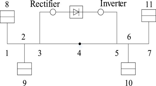
Figure 2. Improved structure diagram of IEEE 11 system.
The parameters of the AC lines in the system are shown in Table 1, and the parameters of the DC lines are shown in Table 2, all represented in per unit values.
Table 1. AC line parameters.
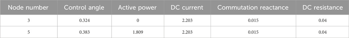
Table 2. DC line parameters.
3.2 Results of the example
Comparing the computational results between the UIM and the proposed approach, the computation times are presented in Table 3. With the same convergence achieved in 5 iterations, the UIM has a computation time of 0.02 s, while the IUIM has a computation time of 0.004 s. With the same convergence accuracy, the computational speed has been improved, showing an 80% increase in speed.

Table 3. Comparison of calculation time.
Comparing the injected active and reactive power of branches as shown in Figures 3A, B, the active power exhibits virtually no error. The maximum deviation for active power input (output) of branches is
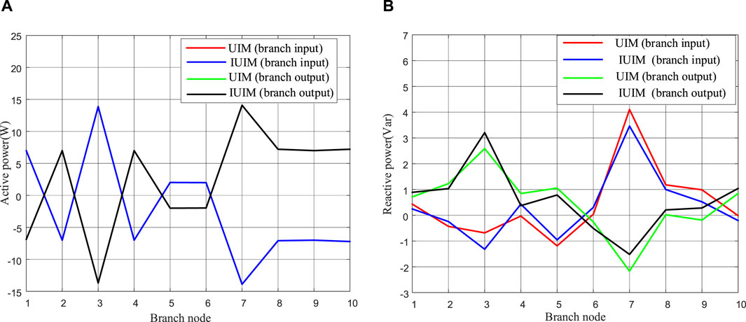
Figure 3. Comparison of power input and output of branch. (A) Active power. (B) Reactive power.
Comparing the voltage transformation ratio of the DC converter as shown in Figure 4, the deviation for the DC converter ratio
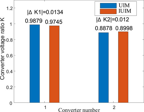
Figure 4. Comparison of voltage ratio of DC converter.
Comparing the calculated node voltage magnitudes as shown in Figure 5A, the maximum voltage deviation between the two calculations is
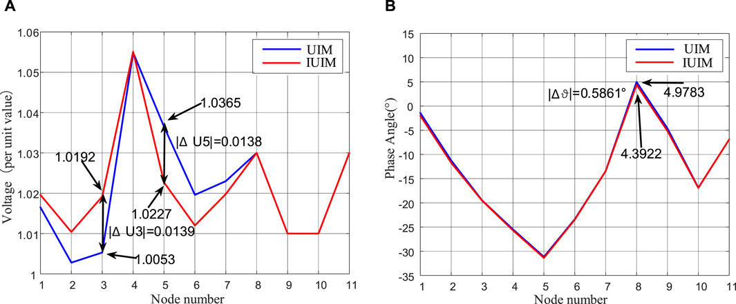
Figure 5. Comparison of Node Voltage Calculation Results. (A) Node voltage amplitude. (B) Node phase.
Based on the simulated results mentioned above, the proposed improved algorithm demonstrates a 80% increase in computational speed while maintaining small computational errors. It meets the requirements of both computational accuracy and efficiency for rapid analysis of microgrids, providing evidence for the feasibility and high computational efficiency of the proposed algorithm.
4 Error analysis
The power flow annotation for the modified IEEE 11-node system structure is shown in Figure 6.
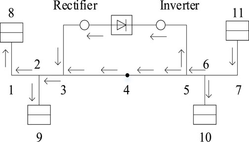
Figure 6. Power flow diagram of the improved IEEE11 system.
From the power flow illustrated in Figure 6, it is evident that for the hybrid AC/DC system, nodes 3 and 5 involve issues regarding the synthesis and distribution of power between AC and DC systems. In this paper, certain DC parameters in the correction equations during DC power flow computation were removed, leading to relative errors between the actual values and the influx and distribution of DC power at the interface nodes between the DC and AC systems. Figure 7 shows the phase error curve of node voltages. As the electrical distance between nodes and the reference node increases, the phase error of node voltages gradually increases. In multi-node radial networks, an increase in the electrical distance between nodes and the reference node leads to a gradual increase in calculation errors. However, for microgrid systems with lower voltage levels, where the electrical distance between nodes is shorter, the errors generated by the improved algorithm are relatively small.
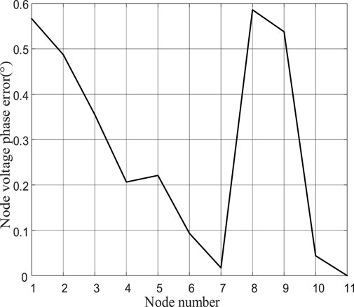
Figure 7. Node voltage phase error curve.
Comparing Eqs 11, 12, the deviation of active power and reactive power for a single iteration process at a certain node in the system is given by Eq. 13:
Analyze the impact of
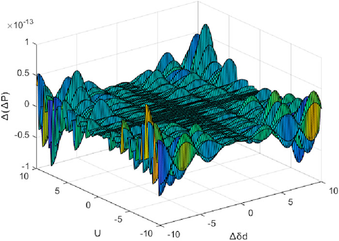
Figure 8. Active power error influence trend.
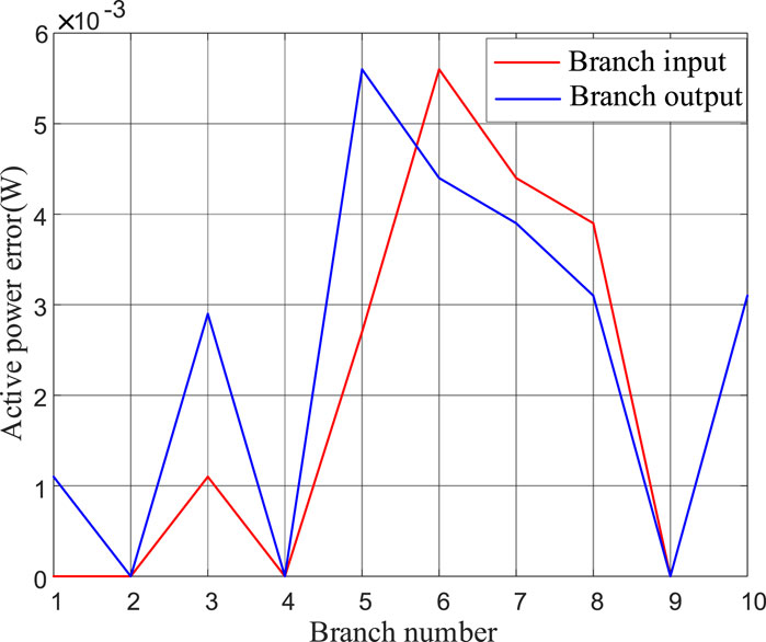
Figure 9. Active power error curve.
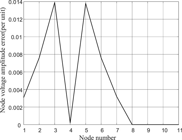
Figure 10. Node voltage error curve.
From Figure 8, it can be observed that when
At lower voltage levels,
Analyze the impact of
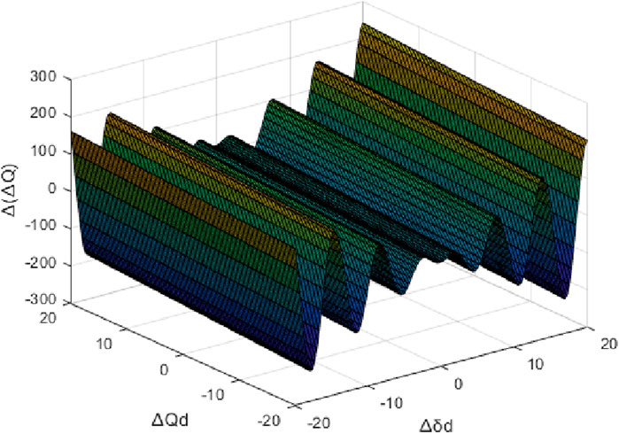
Figure 11. Reactive power error influence trend.
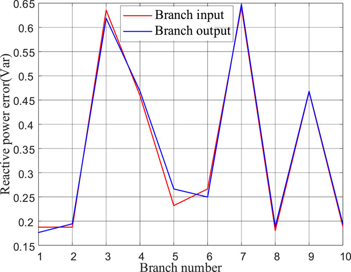
Figure 12. Reactive power error curve.
When
Observing Figure 12, it can be noted that there are significant errors in the reactive power on branches with the branch numbers 3, 4, 7, and 9. In the example, where the voltage phase
For systems with numerous parallel AC and DC lines in the network, the convergence and distribution of AC and DC power flows occur at the connection points. Ignoring
In summary,
5 Experimental verification
5.1 Experimental platform
To further validate the feasibility of the proposed improved algorithm, experimental verification was conducted on the experimental platform shown in Figure 13.
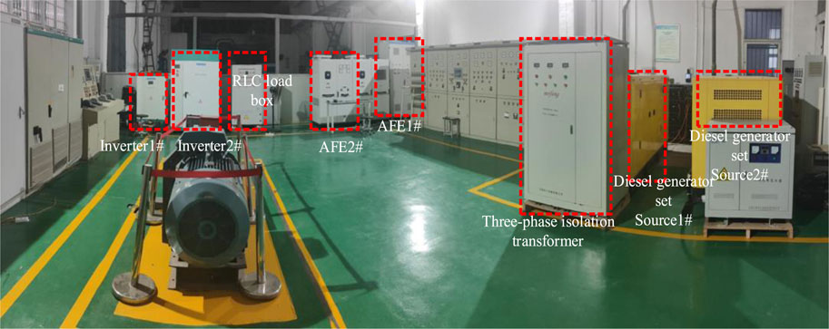
Figure 13. Field diagram of the experimental platform.
Table 4 shows the specific data of the experimental equipment in the experimental platform.
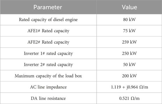
Table 4. Main parameters of the experimental platform.
Equivalent the experimental platform to the system wiring diagram as shown in Figure 14, and assign node numbers to the nodes in the system. Set node 10 as the Slack node with
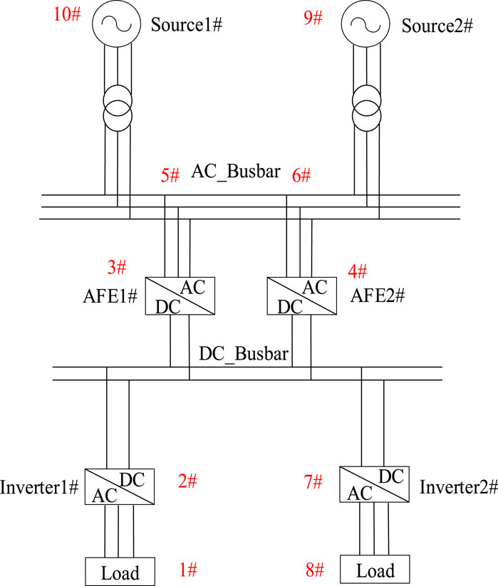
Figure 14. System wiring diagram.
5.2 Experimental result
The voltage waveforms of AFE1# and AFE2# detected by the upper computer under 30kW and 70 kW loads are shown in Figure 15A. The output power waveforms are illustrated in Figure 15B.
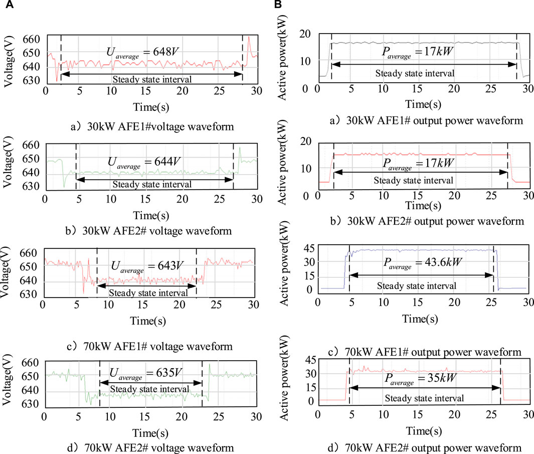
Figure 15. Data acquisition results for AFE1# and AFE2#. (A) Voltage waveform. (B) Power waveform.
Utilizing the proposed improved algorithm to obtain the current power flow solution for the system, and comparing the calculated values with the steady-state values measured by the upper computer. The error results for different loads are presented in Tables 5, 6.
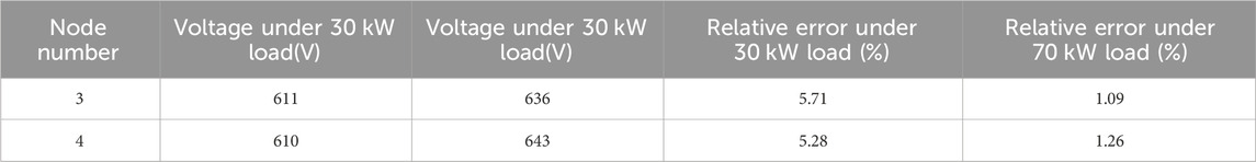
Table 5. Voltage calculation results and relative errors.
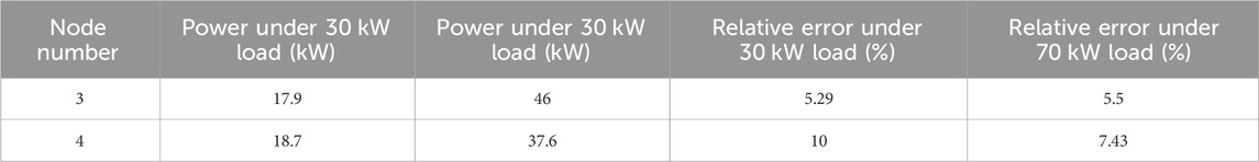
Table 6. Power calculation results and relative errors.
In summary of the above experimental results, for the 30 kW load experiment, the output power error of Node 4 is 10%, and the errors of other node variables are around 5%. For the 70 kW load experiment, the output power error of Node 4 is 7.43%, the output power error of Node 3 is 5.5%, and the voltage error is around 1%.
Comparing the error results of the two experiments, the voltage error results of AFE1# and AFE2# nodes are basically similar. AFE1# has a relatively smaller output power error compared to AFE2#. According to the error analysis results in Section 4, AFE1# is closer to the load in electrical distance, has a smaller line resistance, and requires relatively fewer iterations throughout the calculation process. Therefore, it generates a relatively smaller relative error.
Based on the experimental validation above, the error range between the overall actual measurements and calculated values is within 10%, ensuring relatively accurate results while maintaining computational speed. This verifies the feasibility of the proposed improved algorithm. Particularly in hybrid AC/DC microgrid systems with short electrical distances, this algorithm demonstrates applicability.
6 Conclusion
This paper, based on the characteristics of DC systems, simplifies the correction equations of the unified iteration method and proposes a power flow calculation model for hybrid AC/DC microgrids based on the improved unified iteration method. The following conclusions can be drawn through theoretical analysis and simulation/experimental verification:
1. By neglecting the flow of reactive power within the DC system and the influence of phase angles on the system, the Jacobian matrix in the correction equations of the unified iteration method is simplified and reduced in order to derive a power flow calculation method for hybrid AC/DC microgrids based on the unified iteration method. The case results indicate that the proposed improved algorithm improves computational speed by 80% compared to the Unified Iterative Method.
2. For the proposed improved algorithm, the error in active power is mainly influenced by the voltage phase angle (
3. To experimentally validate the proposed improved algorithm, the magnitude of errors generated for different nodes is related to the electrical distance between the nodes and the load nodes. The longer the electrical distance, the more iterations are required during the power flow calculation process, leading to larger errors.
Data availability statement
The raw data supporting the conclusion of this article will be made available by the authors, without undue reservation.
Author contributions
XD: Writing–original draft, Writing–review and editing. HW: Writing–review and editing. CZ: Writing–review and editing. WY: Writing–review and editing. RY: Writing–review and editing. LX: Writing–review and editing. WL: Writing–review and editing. CL: Writing–review and editing.
Funding
The author(s) declare that financial support was received for the research, authorship, and/or publication of this article. This paper was supported by the National Natural Science Foundation of China (52171308); Natural Science Foundation of Fujian Province, China (2022J01333); Innovation Laboratory for Sciences and Technologies of Energy Materials of Fujian Province and 2022J01813.
Conflict of interest
The authors declare that the research was conducted in the absence of any commercial or financial relationships that could be construed as a potential conflict of interest.
The author(s) declared that they were an editorial board member of Frontiers, at the time of submission. This had no impact on the peer review process and the final decision.
Publisher’s note
All claims expressed in this article are solely those of the authors and do not necessarily represent those of their affiliated organizations, or those of the publisher, the editors and the reviewers. Any product that may be evaluated in this article, or claim that may be made by its manufacturer, is not guaranteed or endorsed by the publisher.
References
Bajpai, R. S. (2023). An efficient MPC-based Droop control strategy for power sharing in a hybrid AC/DC microgrid using renewable energy resources. IETE J. Res., 1–15. doi:10.1080/03772063.2023.2173664
Chen, H., Zhinong, W., and Shen, H. (2017). Three-term decoupling power flow algorithm for isolated AC-DC hybrid microgrids based on sequence components. Electr. Power Autom. Equip. 37 (09), 31–37+45. doi:10.16081/j.issn.1006-6047.2017.09.005
Chen, P., Xiao, X., and Tang, S. (2019). Equivalent Algorithm of interval power flow in AC/DC hybrid distribution Network. Proc. CSEE 39 (04), 979–992. doi:10.13334/j.0258-8013.pcsee.180424
Guoqing, L., Jing, B., and He, W. (2017). Review on DC grids power flow analysis and control. High. Volt. Eng. 43 (4), 1067–1078. doi:10.13336/j.1003-6520.hve.201700328002
Hameed, F., Ai Hosani, M., and Zeineldin, H. H. (2019). A modified backward/forward sweep load flow method for islanded radial microgrids. J. Technol. 10 (1), 910–918. doi:10.1109/tsg.2017.2754551
Heidary, J., Gheisarnejad, M., and Khooban, M. H. (2023). Stability enhancement and energy management of AC-DC microgrid based on active disturbance rejection control. Electr. Power Syst. Res. 217, 109105–109113. doi:10.1016/j.epsr.2022.109105
Huang, Y., Ai, X., Fang, J., Cui, S., Zhong, R., Yao, W., et al. (2023). Holomorphic embedding power flow modeling of autonomous AC/DC hybrid microgrids. Int. J. Electr. Power and Energy Syst. 145, 108549. doi:10.1016/j.ijepes.2022.108549
Ju, Y., Liu, W., Zhang, Z., and Zhang, R. (2022). Distributed three-phase power flow for AC/DC hybrid networked microgrids considering converter limiting constraints. IEEE Trans. Smart Grid 13, 1691–1708. doi:10.1109/tsg.2022.3140212
Lee, J.-Oh, Kim, Y.-Su, and Moon, S.-ll (2020). Current injection power flow analysis and optimal generation dispatch for bipolar DC microgrids. IEEE Trans. Smart Grid 12, 1918–1928. doi:10.1109/TSG.2020.3046733
Li, Z., Xie, X., Cheng, Z., Zhi, C., and Si, J. (2023). A novel two-stage energy management of hybrid AC/DC microgrid considering frequency security constraints. Int. J. Electr. Power and Energy Syst. 146, 108768. doi:10.1016/j.ijepes.2022.108768
Lin, L., Dong, S., and Zhu, C. (2020). Power flow calculation of isolated island microgrid based on two-step solution of cofactor. Power Grid Technol. 44 (10), 3955–3963. doi:10.13335/j.1000-3673.pst.2019.1942
Liu, K., Chun, W., and Wu, H. (2019b). A method for calculating linear power flow in distribution network with PV nodes. Power Syst. Prot. Control 47 (03), 17–22.
Liu, K., Wang, C., and Chen, Y. J. (2019a). Linear power flow calculation of distribution networks with distributed generation. IEEE Access (7), 44696–44695. doi:10.1109/ACCESS.2019.2909325
Liu, Y., Li, Z., and Fan, M. (2021). A Newton-Raphson-Based sequential power flow algorithm for hybrid AC/DC microgrids. IEEE Trans. Industry Appl. 58, 843–854. doi:10.1109/tia.2021.3123246
Nejabatkhah, F., Yunwei, L., and Hao, T. (2019). Power quality control of smart hybrid AC/DC microgrids: an overview. IEEE Access 7, 52295–52318. doi:10.1109/access.2019.2912376
Peng, H., Shuaihu, L., Hui, L., and Huang, X. (2017). Power Flow calculation of AC-DC hybrid microgrids operating in isolatedislands. Power Grid Technol. 41 (09), 2887–2896. doi:10.13335/j.1000-3673.pst.2017.0379
Pengfei, L. V. (2022). Research on HVDC operation characteristics under influence of hybrid AC/DC power grids. Power Syst. Technol. 46 (02), 503–510. doi:10.13335/j.1000-3673.pst.2021.2403
Song, L., Jianwei, L., and Dong, Y. (2021). Flexible power control and voltage suppression strategy for multi-sub-microgrid AC-DC hybrid distribution system. Electr. Power Autom. Equip. 41 (05), 99–106. doi:10.16081/j.epae.202105030
Song, Z., Yaohui, H., and Zhao, H. (2023). Applicability analysis of power flow calculation method for AC-DC hybrid power network with multiple types of DC [J/OL]. Electr. Power Autom. Equip., 1–10. doi:10.16081/j.epae.202307004
Wang, J., Xin, A., Wang, K., and Li, R. (2018). A new AC-DC decoupling power flow algorithm based on Augmented Jacobian Matrix. Trans. China Electrotech. Soc. 33 (06), 1382–1389. doi:10.19595/j.cnki.1000-6753.tces.170277
Wang, X., Peng, C., and Sun, H. (2023). Power flow calculation for AC-DC hybrid power networks considering VSC control strategy. Proc. CSEE 43 (10), 3731–3742. doi:10.13334/j.0258-8013.pcsee.212339
Yang, G. K., Dong, P., Liu, M., and Wu, H. (2021). Research on random fuzzy power flow calculation of AC/DC hybrid distribution network based on unified iterative method. IET Renew. Power Gener-ation 15, 731–745. doi:10.1049/rpg2.12063
Yang, Z. F., Xie, K. G., Yu, J., Zhong, H., Zhang, N., and Xia, Q. X. (2019). A general formulation of linear power flow models: basic theory and error analysis. IEEE Trans. Power Syst. 34 (2), 1315–1324. doi:10.1109/tpwrs.2018.2871182
Zhu, L., Rong, X., Zhao, J., Zhang, H., Zhang, H., Jia, C., et al. (2022). Topology optimization of AC/DC hybrid distribution network with energy router based on power flow calculation. Energy Rep. 8, 1622–1638. doi:10.1016/j.egyr.2022.02.208
Zou, Z., Wang, C., and Zhang, C. (2022). Linear power flow calculation of isolated island microgrid based on sag control. Laboratory Res. Explor. 41 (05), 124–129. doi:10.19927/j.cnki.syyt.2022.05.027
Nomenclature
Keywords: hybrid ac/dc microgrid, power flow algorithm, system characteristics, unified iteration method, matrix reduction
Citation: Dong X, Wang H, Zhang C, Yu W, Yang R, Xiao L, Liao W and Luo C (2024) The power flow algorithm for AC/DC microgrids based on improved unified iteration method. Front. Energy Res. 12:1376714. doi: 10.3389/fenrg.2024.1376714
Received: 26 January 2024; Accepted: 22 April 2024;
Published: 30 May 2024.
Edited by:
Xiongbo Duan, Central South University, ChinaCopyright © 2024 Dong, Wang, Zhang, Yu, Yang, Xiao, Liao and Luo. This is an open-access article distributed under the terms of the Creative Commons Attribution License (CC BY). The use, distribution or reproduction in other forums is permitted, provided the original author(s) and the copyright owner(s) are credited and that the original publication in this journal is cited, in accordance with accepted academic practice. No use, distribution or reproduction is permitted which does not comply with these terms.
*Correspondence: Weiqiang Liao, d3FfbGlhb0BqbXUuZWR1LmNu