 Conghuan Yang
 Qingtao Zhang2
- 1Guangzhou Maritime College, Guangzhou, China
- 2Logistics Engineering College, Shanghai Maritime University, Shanghai, China
- 3School of Electric Power Engineering, South China University of Technology, Guangzhou, China
The AC power system strength exhibits time-varying characteristics during operation, thereby affecting the filtering performance of filters in the system. Failure to account for this variability may result in the harmonic levels exceeding permissible limits under specific power system strength, thereby affecting the normal operation of the power system. Consequently, building upon the existing filtering technique based on parallel-connected fixed capacitors for LCC-HVDC systems, a method for tuning the parameters of parallel-connected capacitors is proposed, thereby the capacitance range meets the filtering requirements under various system strengths.
1 Introduction
High voltage direct current (HVDC) transmission technology plays an important role in large-capacity and long-distance transmission applications (Agelidis et al., 2006; Tang and Xu, 2014). However, with the increasing number of converter stations in the power system, the harmonic levels in the power grid are also rising (Xin et al., 2020). Excessive harmonics can lead to distortion of the AC waveform and reactive power deficits (Xue et al., 2019), posing a serious threat to the safe operation of the power system (Geng et al., 2018). To address this issue, power grid companies have established the corresponding harmonic content standard (IEEE, 2014), specifying that the Total Harmonic Distortion (THD) value of harmonic voltage and current should not exceed 1.5%. To meet the standards, effective measures need to be taken. AC filters are essential components in HVDC transmission system for mitigating harmonics (Lee et al., 2015). In addition, the AC power system strengths have a significant impact on the operation of the power grid and the strengths can be quantified using the short-circuit ratio (SCR) (Li et al., 2020). Li et al. (2022) provide the typical variation of the SCR and its impact on the frequency and voltage stability. Lower AC strength corresponds to lower resonance frequencies and an increasing risk of resonance, leading to the degradation of the system’s normal performance and distortion of voltage. In summary, weak AC power system strength can weaken the system’s robustness and stability. Increasing the AC power system strength is beneficial for raising the system’s resonant frequency and stability, while achieving the better filtering effects (Chen et al., 2018).
For LCC-HVDC systems, it is necessary to consider both the reduction of AC harmonics and the compensation of reactive power (Liu and Zhu, 2013). Traditionally, active or passive filters are commonly employed to achieve these objectives. The circuit topology of passive filters is relatively simple, but they suffer from drawbacks such as large space requirements and poor filtering effectiveness due to the resonance points shifting. Consequently, research and application of active filter have become more extensive. Various design approaches for active filters have been proposed (Yang et al., 2022; Farghly et al., 2022; Du et al., 2022), addressing aspects such as optimizing the multi-topology structure of passive filters, parallel filtering structures based on hybrid systems, and adopting two-parallel single-tuned LC structures while considering the time-delay effect of controllers. The designed filters can effectively reduce harmonics and simultaneously reduce the size of capacitor banks to reduce reactive power compensation. Liu et al. (2020) consider the coordination between hybrid active filters and existing reactive power compensation devices. They introduce a novel AC filtering system that utilizes a series-connected passive resonance topology and a control scheme for active filtering. This not only enhances the harmonic suppression performance of LCC-HVDC, but also optimizes the reactive power compensation between different filter groups thereby reducing HVDC costs.
The above filtering technologies typically require the addition of AC filter stations. This entails significant space occupation, and the necessity to address issues such as losses and maintenance. Therefore, novel filtering technique have been proposed. Huang et al. (2022) introduce a hybrid active power filter with simple combination of passive filters and IGBT valves. The selected passive filter capacity and topology effectively enhance the filtering efficiency while ensuring independence between the filter and AC system, preventing resonance. However, the system configuration cost is high and the control of IGBT valves is difficult. A novel induction filtering technique based on the field-circuit coupling calculation method is proposed by Li et al. (2012), which greatly reduces the harmonic current content, enhances the excitation performance, improves the electromagnetic environment, and reduces the harmonic losses of HVDC converter transformers. Zhai et al. (2017), Zhao et al. (2022), and Xue et al. (2018) propose a novel filtering technique based on parallel-connected fixed capacitors in HVDC converters, which effectively suppresses harmonics without external AC filters and reactive power compensation devices. It also provides reactive power compensation and suppresses the commutation failure. This filtering method successfully address the issues associated with traditional filters. Nevertheless, the above studies do not take into account the impact of AC power system strength on the filtering performance of the filters. Power system strength is a crucial indicator of power system stability and play a vital role in power system operation. For the novel filtering technique involving the addition of parallel-connected fixed capacitors, it is crucial to consider whether the capacitance of the parallel capacitor can still maintain the system stability and meet the harmonic requirement under the varying system strengths.
To address aforementioned problems, this paper analyzes the impact of system strength on the filtering. Additionally, a tuning method for parallel-connected capacitors is proposed considering power system strength, establishing a capacitance range that meets filtering standards. This method not only contributes to the fault and transient analysis of novel filtering technique involving parallel-connected fixed capacitors but also provide valuable guidance for the configuration of capacitance parameters in practical engineering.
The filtering methods of different references are classified in Table 1.
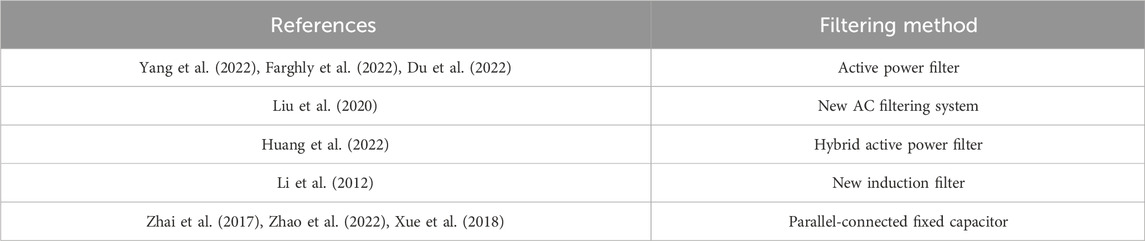
TABLE 1. Classification of different filtering methods.
The rest of the paper is organized as follows: Section 2 introduces the operation principle of novel filtering technology. Section 3 proposes a parameter tuning method for parallel-connected fixed capacitors. Section 4 validates the theoretical result and determines the range of capacitor capacitance. Section 5 combines the simulation to further determine the range of capacitor capacitance. Brief conclusions are drawn in Section 6.
2 Operation principle of novel filtering technique
In response to the shortcomings associated with the traditional filters, Xue et al. (2018) propose a novel filtering technology by adding parallel-connected fixed capacitors to the inverter side of the converter station.
The circuit diagrams for the novel filtering technique are shown in Figures 1, 2, where Ls is the smooth inductance, Lc is the transformer equivalent inductance, Rs is the DC resistance, TY(D)1∼TY(D)6 are the thyristors of the converter bridge, CapY(D)ab, CapY(D)bc, CapY(D)ac are the parallel-connected fixed capacitors, LY(D)abc are series inductance, mainly used for absorbing surplus reactive power. Ca is the DC filtering capacitor, Zinv is the equivalent impedance of AC system at the inverter side, and Zsys(n) is the grid impedance at the nth harmonic frequency.

FIGURE 1. Circuit topology at the inverter side of the system.
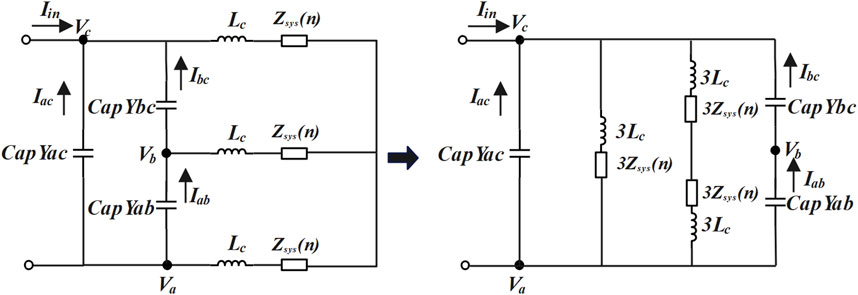
FIGURE 2. Equivalent circuit.
It can be seen from Figure 2 that the impedance of the capacitor branch will be small at high-frequencies, allowing a large AC current to flow through this branch. This causes the high-frequency AC harmonics to be “short-circuited” by the capacitors, achieving harmonic reduction. This further achieves the dual purpose of harmonic filtering and reactive power compensation. Xue et al. (2018) compare the simulation results between traditional and novel filtering technique, demonstrating that the latter can achieve similar filtering effects.
The novel filtering technique not only addresses the limitations of traditional filtering but also achieves filtering effort with a reduced amount of reactive power compensation. Therefore, studying the influence of power system strength on filtering effectiveness based on this novel filtering technique is of significance.
3 Tuning method for capacitance parameter
In this section, taking into account the AC system strength for system reactive power and harmonic content are derived. Additionally, the capacitance tuning method is introduced.
3.1 Reactive power calculation
Figure 3 highlights the definitions of reactive power at different parts of the system. In Figure 3, TY(D)1∼6 are the thyristors of the converter bridge, CapY(D)ab,CapY(D)bc,CapY(D)ac are the parallel-connected fixed capacitors, LY(D)abc are the series inductance, and Zinv is the equivalent impedance of AC system at inverter side.
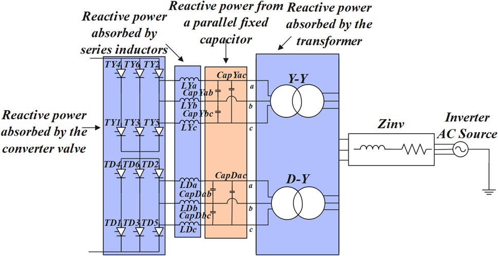
FIGURE 3. Circuit diagram with reactive power measurements.
The reactive power absorbed by the converter can be calculated by Equation 1:
where Vac is the phase voltage amplitude, Vdc is the DC-side voltage, and Pmax is the maximum rated power.
The reactive power absorbed by the transformer can be calculated by (2):
where S is the capacity of the transformer and pf is the power factor.
The transformer power factor is shown in (3):
where Lc is the transformer equivalent inductance.
If the ratio of the transformer is k, the reactive power generated by the parallel-connected fixed capacitor is shown in (4) and (5):
where V2 is the phase voltage amplitude of bus.
The reactive power absorbed by the series inductance changes with the variation of capacitance and its value is relatively small. Therefore, to simplify the calculation, its impact is not considered in the theoretical calculations.
3.2 Harmonic content calculation
Xue et al. (2018) provide the harmonic amplitude expressions with AC power system strength of 2.5. Based on the twelve-pulse bridge, the expressions for C-phase harmonic current and voltage amplitude are shown in (6) and (7):
Where, Zsys(n) is the grid impedance at the nth harmonic frequency, C is the capacitance of the parallel-connected fixed capacitor,
HVDC transmission system interaction are largely determined by the AC power system strength relative to the DC transmission capacity. The degree of strength is often assessed using the short-circuit ratio (SCR).
The definition of the Multiple Input Short Circuit Ratio (MISCR) is given by Wang et al. (2021) as (8):
Where, Saci is the short-circuit capacity of bus i, PdiN is the rated power of bus i, MIIF indicates the interaction between the converter buses.
For single-infeed system, the SCR can be derived as shown in (9):
Where, Z is the inherent impedance of grid, Zdc is the grounding impedance. Figure 4 is the HVDC equivalent impedance model at the inverter side. In Figure 4, the grounding impedance (Zdc) includes the equivalent impedance of the converter valves and transformer. The inherent impedance (Z) is the equivalent impedance of the system. The grounding impedance can be considered fixed as the network frequency normally does not vary. Thus, the relationship between the SCR and the equivalent impedance Z of the power grid according to (9) can be expressed as shown in Figure 5. It can be seen from the relationship curve in Figure 5 that the SCR is inversely proportional to the equivalent impedance (Z) of the power grid. Since the grounding impedance (Zdc) includes the equivalent impedance of the transformer, and Xue et al. (2018) separate the equivalent impedance of the transformer and the impedance of the capacitor for calculation, this paper adopts the following methods to calculate the harmonic amplitude under the different system strengths to simplify the calculation.
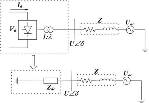
FIGURE 4. Equivalent impedance model.
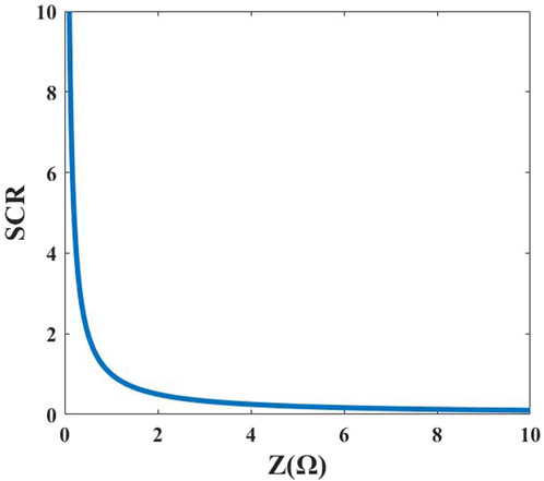
FIGURE 5. Relationship between Z and SCR
The basic short-circuit ratio (SCR) accounts for the inherent strength of AC power system, and the corresponding expression is given by Jia et al. (2012) as (10):
Short-circuit capacity SSC(MVA) is defined as (11):
Where, Eac is the commutation bus voltage under rated DC power, Zth is the grid impedance at the nth harmonic frequency and PdN is the rated DC power.
The relationship between grid impedance and AC power system strength can be expressed as (12):
Where, Zsys(n) represents the grid impedance at the nth harmonic frequency. It can be seen from (12) that grid impedance is inversely proportional to the short-circuit ratio (SCR).
By substituting (12) into (6) and (7), the expressions for C-phase harmonic current and voltage amplitude associated with system strength based on the twelve-pulse converter bridge can be obtained as follows:
From (13) and (14), it can be observed that when the other parameters are constant and the equivalent inductance of the transformer is small enough to be negligible, the change of SCR with respect to harmonic current and voltage is as follows: As SCR increase, the amplitude of harmonic current and voltage decreases.
3.3 Capacitance parameter tuning process
This section introduces the tuning of capacitance considering the system strength. As shown in Figure 6, the process primarily involves two aspects: 1) Reactive power compensation. 2) Filtering effect. The priority is: Reactive power compensation and then the filtering effect. The tuning method is suitable for the conventional LCC-HVDC system.
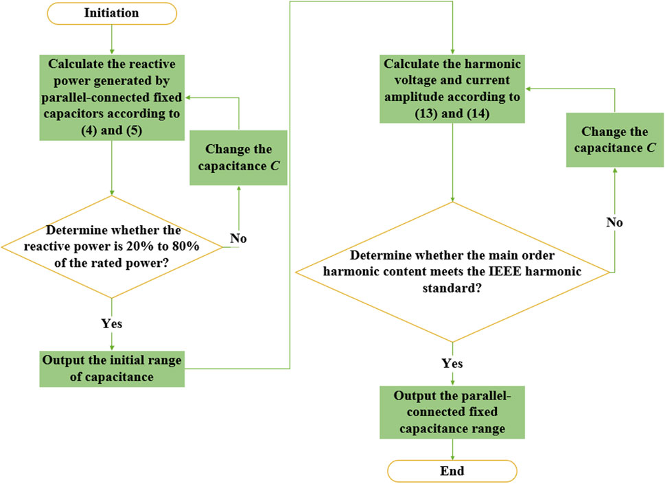
FIGURE 6. Capacitance tuning process.
3.3.1 Reactive power compensation
According to (5), the reactive power is generated by the capacitor. Typically, the reactive power compensation at the inverter side falls within the range of 40%–60% of the rated power. To fully study the impact of small capacitance on filtering performance, the range of the reactive power compensation is extended to 20%–80% of the rated DC power. If the reactive power compensation exceeds this range, the capacitance is not considered. Otherwise, it can be considered.
3.3.2 Filtering effect
According to the capacitance range initially determined by the reactive power compensation, the filtering effect of the capacitance in this range is further tested. According to the harmonic amplitude expressions (6) and (7), the harmonic content under different system strengths is calculated. Then, compared with the IEEE harmonic standard, the capacitance range is further determined.
4 Theoretical results of capacitance tuning method
The range of capacitance is determined using the tuning method from Section 3. The results are calculated based on CIGRE HVDC benchmark model.
4.1 Results of reactive power under the system strength of 2.5
Firstly, the capacitance range is initially determined by the reactive power compensation.
Figure 7 shows the change of reactive power under varying capacitance. It can be seen that the reactive power generated by the capacitors increases with the increase of capacitance, following a positive trend. Reactive power balance is achieved when the capacitance reaches 8.25 μF. In addition, the capacitance range that fulfills the reactive power compensation is approximately 3 μF–11.5 μF, in consistence with the initial capacitance range.
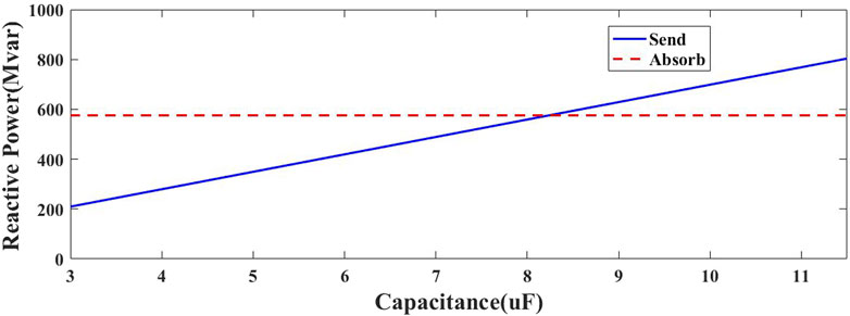
FIGURE 7. Reactive power change curve.
4.2 Results of harmonic content under the system strength of 2.5
From the relationships shown in (6) and (7), the harmonic content decreases with the increase of capacitance. Besides, the capacitance is not limited in a certain range. Xue et al. (2018) also provide the harmonic content under the system strength of 2.5, and this paper calculates the harmonic content under the same condition. According to the IEEE grid harmonic standards, the capacitance range that meets the requirements is approximately 7 μF to +∞μF.
In summary, the capacitance range that meets the reactive power compensation requirement and harmonic standard is 7 μF–11.5 μF when the AC power system strength is 2.5.
4.3 Results of harmonic content under different AC power system strengths
Based on the obtained capacitance range under the system strength of 2.5, the harmonic content of capacitors within this range is analyzed for different system strengths. Figure 8 illustrates the filtering performance of capacitors with capacitances of 7 μF, 8.8 μF and 11.5 μF under varying AC power system strengths. The selection method of the capacitance of 8.8 μF is as follows: Based on the compromise of the capacitance range of 7 μF–11.5 μF obtained in part A and B above and combined with the simulation test that can achieve stable capacitance value under rated working conditions. It can be observed that the harmonic content for 7 μF, 8.8 μF and 11.5 μF capacitors generally complies with the harmonic standards. Moreover, for a fixed capacitance, as the strength increases, the harmonic content decreases, indicating better filtering effectiveness.
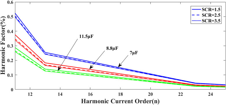
FIGURE 8. The harmonic content under different AC power system strengths.
In conclusion, the capacitance range for parallel-connected fixed capacitors that meets the requirement is 7 μF–11.5 μF.
5 Simulation results of capacitance tuning method
The analysis and calculation methods discussed above are applicable to systems with any strength.
This paper utilizes MATLAB/Simulink software to construct the LCC-HVDC system based on the parameters of the CIGRE benchmark model. The system model is shown in Figure 9.
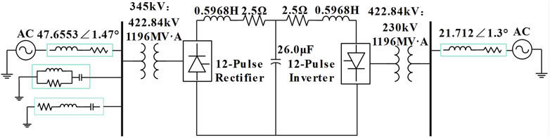
FIGURE 9. System model A.
5.1 Simulation results of reactive power under the system strength of 2.5
In this section, simulation results are employed to validate and analyze the reactive power generated by capacitors with different capacitance.
Figure 10 shows the relationship between capacitance and reactive power for capacitance value ranging from 20% to 80% of the rated DC power. It is evident that the capacitance and the generated reactive power exhibit an approximate correlation. The system achieves the reactive power balance when the capacitance reaches 8.25 μF.
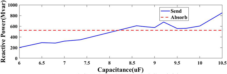
FIGURE 10. Reactive power change curve.
Observing the simulation result, the acceptable capacitance range is 6 μF–10.5 μF. By comparing with the theoretical results from Figure 7, there is a small discrepancy between them. The reasons are as follows:
Equation 15 is derived from (4) and (5). It shows the reactive power generated by the capacitor.
It can be observed that when capacitance and frequency are constant, factors affecting reactive power include the phase voltage on the primary side of the transformer (V2) and the transformer turns ratio (k). In theoretical calculations, the values of both are derived based on the benchmark model parameters. In the simulation test, to ensure the system adjusts to the rated operating conditions, the grid side is equivalent to an ideal voltage source, and the transformer turns ratio may vary, leading to discrepancies between the theoretical and simulated values. Additionally, when capacitance reaches a certain level, series inductance is required to absorb additional reactive power, which is not considered in the theoretical calculations.
5.2 Simulation results of harmonic content under the system strength of 2.5
This section begins with the analysis of the filtering effect, conducting simulation analysis on the harmonic content with different capacitance. Furthermore, by combining theoretical analysis with simulation results, the discrepancies between the two are analyzed.
Figure 11 depicts the variation in THD and Figure 12 illustrates the simulation results for the main harmonic content when the capacitance is between 6μF and 10.5 μF.
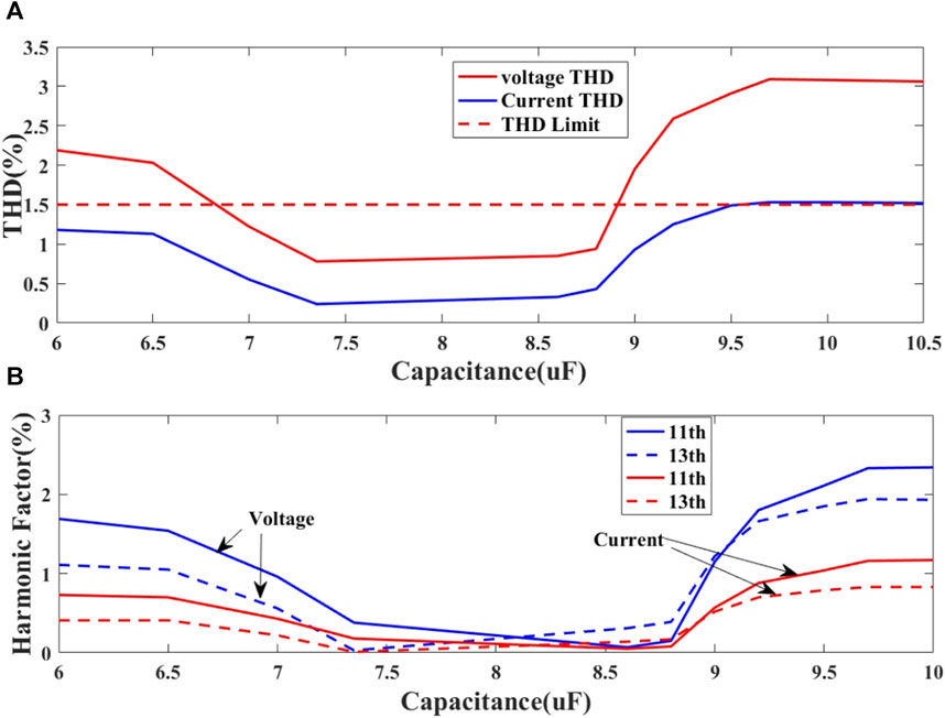
FIGURE 11. Harmonic content under varying capacitance. (A) THD values under varying capacitance. (B) Main orders harmonic content under varying capacitance.
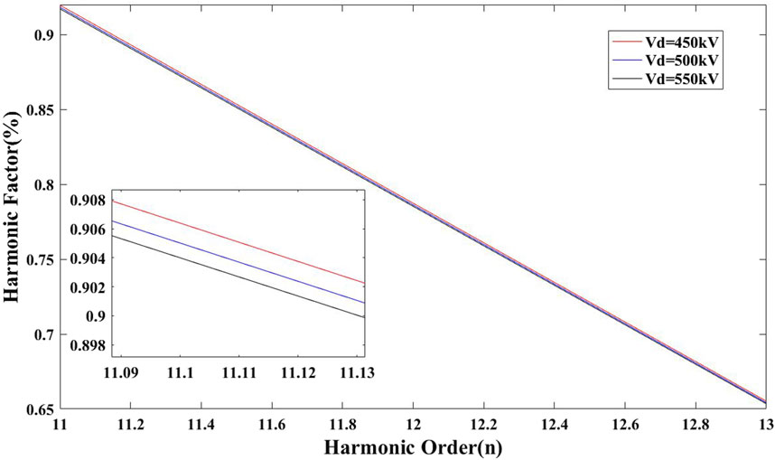
FIGURE 12. Harmonic content under different DC voltages.
5.2.1 Results analysis
Figure 11A depicts the THD variation for voltage and current. It can be observed that the THD of harmonic current are lower than those of harmonic voltage, and both exhibit similar trends. The THD values of the harmonic current are generally within the required harmonic range, whereas voltage is not. It is obvious that capacitance within a certain range complies with the IEEE harmonic standards.
Comparing Figure 10 and Figure 11A, it can be observed that when the system does not reach reactive power balance or when the capacitance is small, the reactive power compensation is much less than the reactive power absorbed by the converter station. The filtering effect also falls within the IEEE harmonic standard range. The main reasons are explained as follows:
A. High frequency harmonic currents pass through the capacitor: When the capacitance is small, its impact on the clamping circuit is reduced, leading to a reduction of the reactive power compensation provided by the capacitor. At the same time, the filtering effect of the harmonic currents on the AC side is enhanced because the frequency of harmonic current is usually high, allowing them to pass through the capacitor more easily.
B. Improve the system stability: Although the added capacitance is small, the power factor of the system is still improved, enhancing system stability. This result in that more effective reduction of harmonic current on the AC side after passing through the capacitor, thereby reducing the demand for reactive power on the AC side.
Figure 11B shows the simulation results of the main harmonic content for capacitance ranging from 6 μF to 10.5 μF. It can be observed from Figure 11B that the variation has a concave distribution, and the capacitance range that meets the IEEE harmonic standard is 7 μF–8.8 μF.
Comparing these results with theoretical analysis, there are difference in their variations. Moreover, in the simulation results, a larger capacitance does not necessarily lead to better filtering performance. The main reasons are explained as follows:
A. During the system simulation, the generated reactive power exceeds the reactive power absorbed by the converter station when the capacitance is large. Under this condition, it is necessary to connect a parallel grounding inductor on the AC side of the converter station or connect the series inductor on the AC side of the converter bridge to absorb the surplus reactive power. At this point, the capacitor C and the inductor L form a LC resonant loop. According to the theory of series/parallel resonant circuit, the resonant frequency of the LC resonant circuit can be calculated as shown in (16):
Where, f is the resonance frequency, L is the inductance, and C is the capacitance.
B. The resonance frequency will decrease when the capacitance increases. Moreover, the resonance frequency becomes close to or equal to the system’s resonant frequency when it reaches a certain level, causing resonance and resulting in an increase in harmonic content.
C. The internal impedance of the capacitor also affects the level of harmonic current and voltage. When the capacitance is too large, its losses will increase and the internal impedance also increase, leading to an increase in power consumption and an increase in the harmonic content.
5.2.2 Error analysis
A. During the simulation, the DC voltage do not reach exactly the rated value of 500 kV. Based on this, the relationship between different DC voltages and harmonic current content when other factors are constant is studied. The simulation results are shown in Figure 12, in which, it can be observed that the harmonic current content changes inversely with the DC voltage. The higher the DC voltage, the lower the harmonic current content. Although the variations in DC voltage have a small effect on the change in the harmonic current, the differences in DC voltage will still affect the filtering effect.
B. In the simulation process, the AC voltage is within a certain rated value range, but the AC voltage may not always match the rated value during simulation, and its variation may lead to result deviations. Below is the testing of the THD values for different AC voltage with the same fixed capacitor capacitance.
Figure 13 shows the variation of THD values for different AC voltages with the same fixed capacitor capacitance. Figure 13A, B show the THD values for a capacitance of 7 μF under the system strength of 1.5 and 2, respectively. It can be observed that the harmonic content decreases with the increase in AC voltage, indicating that a higher AC voltage leads to better filtering effect. The rated value of the AC voltage is 187 kV, and the numerical values used in theoretical calculation are based on this rating. However, in the simulation results, the filtering effect for some capacitor capacitances are measured within the range of ±2% of the rated AC voltage (184 kV–191 kV), which introduces deviations in the results.
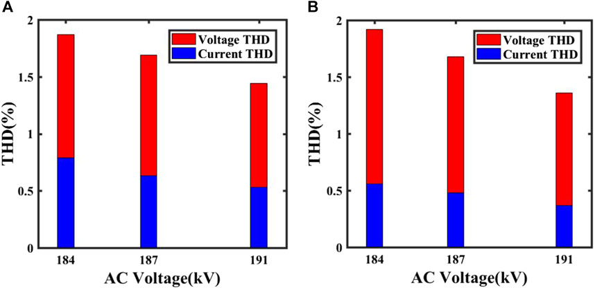
FIGURE 13. Filtering effect under different AC voltages. (A) SCR=1.5 (B) SCR=2.
5.2.3 Potential solutions
A. Optimize the design of the converter station structure: In the design of the converter station structure, it is possible to mitigate resonance between capacitors and line inductors by setting appropriate parameters such as capacitance and inductance. For instance, in the case of a multi-terminal filter structure, the introduction of two small resistors in series between the capacitor and inductor can prevent resonance.
B. Use controllable capacitors: Controllable capacitors can autonomously adjust their capacitance based on the system’s operating conditions, thereby preventing the occurrence of resonance.
C. Dynamically adjust capacitance: Dynamically adjust the capacitance based on the actual operating conditions of the system to ensure system stability and safety.
D. Add additional inductance: Add a certain inductance between capacitors and line inductance to reduce the resonance frequency and thereby avoid resonance.
In summary, the acceptable capacitance range is 7 μF–8.8 μF for the AC power system strength of 2.5.
It should be noted that the methods mentioned above are equally applicable to systems with other system strengths.
5.3 Comparative with existing passive filtering techniques
Table 2 shows the harmonic content using different filtering techniques, with the novel filtering technique provided for capacitor capacitance of 7.35 μF and 8.8 μF. The choice of 7.35 μF is based on the fact that, at this capacitance, the reactive power compensation generated by the capacitor is comparable to the reactive power compensation achieved with a passive filter. This selection allows for a more meaningful comparison of the filtering effects of different techniques.
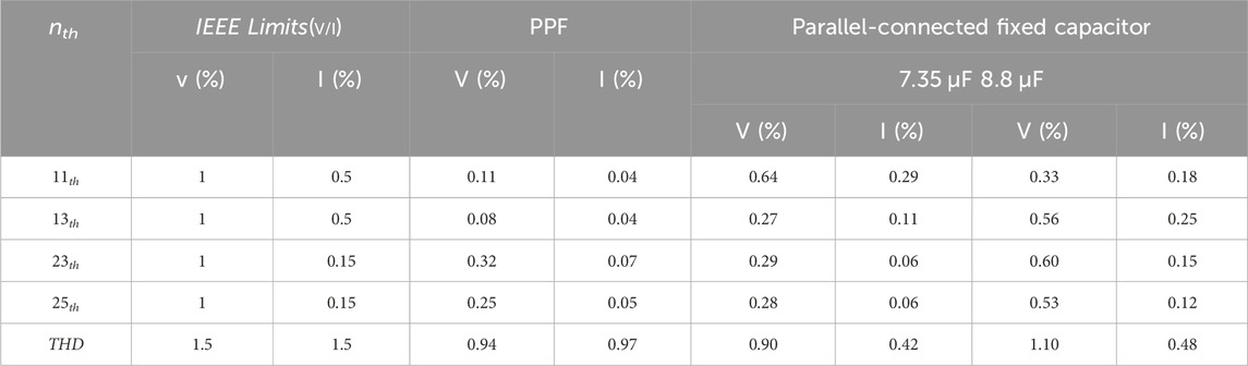
TABLE 2. Comparison of filtering effect under different filtering techniques.
From Table 2, it is observed that the 11th and 13th harmonic content is higher than that of the passive filter, but the high-frequency harmonic content is lower for the capacitance of 7.35 μF. In terms of THD values, with the same reactive power compensation, the filtering effect of the novel filtering technique is superior to that of the passive filter.
For capacitance of 8.8 μF, the reactive power generated by the capacitor is much larger than the reactive power compensation of the passive filter. However, the filtering effects for some harmonics orders is worse than the passive filter, the main reasons are as follows:
A. Impedance of the parallel-connected fixed capacitor itself: The fixed capacitor has a certain internal impedance in the system. When the capacitance is large, the internal impedance also increases, leading to higher losses and increased harmonic content.
B. Resonance issues: When the capacitance is large, it requires series or parallel-connected grounding inductance to absorb the surplus reactive power. In this case, a resonant circuit is formed by the capacitor C and inductor L. With a large capacitance, the resonance frequency decreases, and if it becomes close or equal to the resonance frequencies of other circuits in the system, it may cause resonance issues, leading to a reduction in filtering effectiveness.
C. High-performance broadband of the passive filter: Passive filter can choose different parameters according to requirements to meet the harmonic reduction. By adjusting the parameters of circuit components, better harmonic suppression can be achieved. In contrast, the filtering effect of parallel-connected fixed capacitors can only be effective within a specific frequency range, making it difficult to filter out harmonic signals at other frequencies, and adjustment is challenging.
In summary, both traditional filtering and novel filtering techniques can effectively suppress harmonic interference. However, due to limitations such as the impedance of capacitors, resonance issues and the filtering frequency range, the filtering effects vary under different capacitances. In practical engineering, it is advisable to choose different filtering methods based on actual requirements and grid conditions.
5.4 Simulation result of harmonic content under different system strengths
This section further analyzes the filtering effects under different system strengths.
Figures 14A, B show the simulation results of harmonic current content with the capacitance of 7μF and 8.8 μF under different AC power system strengths. It can be observed that, under various power system strengths, the simulation results for a capacitance of 7 μF are close to the theoretical analysis results, while the results for a capacitance of 8.8 μF differ significantly. The filtering effect on low-frequency harmonics is more obvious, but the filtering effect on high-frequency harmonics is less effective. The main reason for this includes: Parallel-connected fixed capacitors can only filter a certain range of harmonic frequencies, and when the capacitance reaches a certain level, parallel grounding inductance or series the inductance is needed to absorb surplus reactive power. The capacitor may resonate with the inductance, leading to an increase in harmonic content at that frequency.
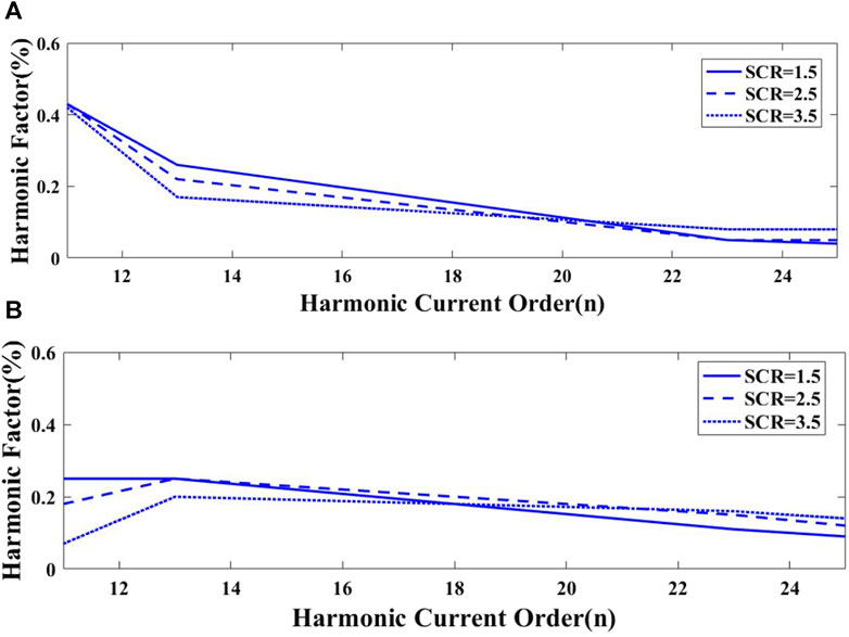
FIGURE 14. Harmonic current content with different capacitance. (A) Harmonic current content with a capacitance of 7 μF (B) Harmonic current content with a capacitance of 8.8 μF.
Besides, the variation follows the following trend under different AC power system strengths: A higher system strength leads to better filtering performance.
Figure 15A, B show the variation of harmonic content with the capacitance of 7 μF and 8.8 μF under different AC power system strengths. It can be observed that the harmonic content for 7 μF and 8.8 μF capacitance can meet the harmonic standard. Except for the case of an AC power grid strength of 1.5, where the 11th harmonic voltage content exceeds the limit for a 7 μF capacitor.
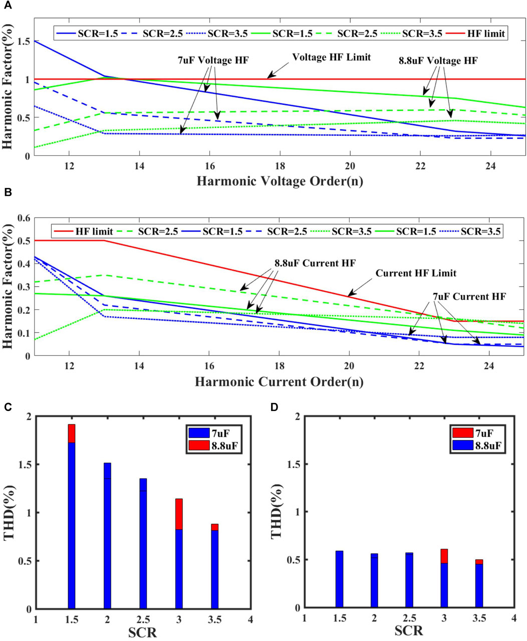
FIGURE 15. Simulation results of harmonic content and THD values with the capacitance of 7 μF and 8.8 μF under different system strengths. (A) Simulation results of harmonic voltage content (B) Simulation results of harmonic current content (C) Harmonic voltage THD (D) Harmonic current THD.
Figure 15C, D illustrates the variation of THD for the capacitance of 7 μF and 8.8 μF under different AC power system strengths. It can be observed that the THD values for both 7μF and 8.8 μF capacitors are within the specified range, expect for the THD under an AC system strength of 1.5.
Based on the above analysis, it can be concluded that the harmonic level for capacitance ranging from 7 μF to 8.8 μF generally complies with the IEEE standard under different system strengths. Additionally, it is evident that a lower system strength can affect the filtering effectiveness.
In summary, take into account the filtering effect under different system strengths, the parallel-connected fixed capacitance range that meets the requirements for both reactive power compensation and the filtering effectiveness is approximately 7 μF–8.8 μF. In practical applications, when taking into account the reactive power balance of the system, the ideal range of capacitance is 8.25 μF–8.8 μF observing Figure 10.
6 Conclusion
This paper proposed a tuning method for the parameter of parallel-connected fixed capacitors considering the system strength based on the novel filtering technique. The method enables the calculation of the range of required capacitance for filtering under varying power system strengths. By analyzing the filtering performance under various power system strengths, this paper reveals that the variation in power system strength affects the filtering performance of the novel filtering technique. Specifically, within a certain range of power system strengths, weaker AC system leads to a reduction of filtering performance. Consequently, a tuning method for the capacitor parameters’ range is proposed for the novel filtering technique considering the power system strengths. This method is effective for LCC-HVDC systems with varying power system strengths. It provides guidance for the selection of filtering capacitance in practical applications.
Data availability statement
The original contributions presented in the study are included in the article/supplementary material, further inquiries can be directed to the corresponding author.
Author contributions
CY: Writing–original draft, Writing–review and editing. QZ: Writing–original draft, Writing–review and editing. ZZ: Writing–review and editing.
Funding
The author(s) declare that financial support was received for the research, authorship, and/or publication of this article. This work was supported in part by the National Natural Science Foundation of China under Excellent Young Scientists Fund (overseas) (A4230010), in part by the Fundamental Research Funds for the Central Universities under Grant 2023ZYGXZR105, in part by the Research Startup Funding from the Guangzhou Maritime University (K42022121).
Conflict of interest
The authors declare that the research was conducted in the absence of any commercial or financial relationships that could be construed as a potential conflict of interest.
Publisher’s note
All claims expressed in this article are solely those of the authors and do not necessarily represent those of their affiliated organizations, or those of the publisher, the editors and the reviewers. Any product that may be evaluated in this article, or claim that may be made by its manufacturer, is not guaranteed or endorsed by the publisher.
References
Agelidis, V. G., Demetriades, G. D., and Flourentzou, N. (2006). “Recent advances in high-voltage direct-current power transmission systems,” in 2006 IEEE International Conference on Industrial Technology, Mumbai, India, 15-17 December, 2006, 206–213.
Chen, K., Luo, J., Zhou, T., Luo, K., Wang, S., and Zang, D. (2018). “Summary of research on multi-infeed short circuit ratio in AC and DC systems,” in 2018 2nd IEEE Conference on Energy Internet and Energy System Integration (EI2), Beijing, China, 22 October 2018, 1–9.
Du, X., Zhao, C., and Xu, J. (2022). The use of the hybrid active power filter in LCC-HVDC considering the delay-dependent stability. IEEE Trans. Power Deliv. 37 (1), 664–673. doi:10.1109/tpwrd.2021.3068411
Farghly, A., El Habrouk, M., Ahmed, K. H., Abdel-khalik, A. S., and Hamdy, R. A. R. (2022). “Active power filter for12-pulse LCC converter employed in LCC-MMC hybrid HVDC system,” in 2022 23rd International Middle East Power Systems Conference (MEPCON), Cairo, Egypt, 13-15 December 2022, 1–7.
Geng, X., Wen, J., Wang, S., He, D., Zhang, L., Cai, Y., et al. (2018). “Modeling and analysis of AC side equivalent harmonic impedance of HVDC converter,” in 2018 2nd IEEE Conference on Energy Internet and Energy System Integration (EI2), Beijing, China, 22 October 2018, 1–6.
Huang, Y., Song, S., Li, M., Wu, F., Zhu, Q., Ji, Y., et al. (2022). “Design of hybrid active filter applied in LCC HVDC project,” in 2022 IEEE International Conference on High Voltage Engineering and Applications (ICHVE), Chongqing, China, 25-29 September 2022, 1–4.
IEEE (2014). IEEE Recommended Practice and Requirements for Harmonic Control in Electric Power Systems. IEEE std 519-2014 (revision of IEEE std 519-1992), 1–29.
Jia, C. C., Wen, J., and Bie, X. Y. (2012). “Study of the effect of AC system strength on the HVDC startup characteristics,” in International Conference on Sustainable Power Generation and Supply (SUPERGEN 2012), Hangzhou, 8-9 September 2012, 1–5.
Lee, T. L., Wang, Y. C., Li, J. C., and Guerrero, J. M. (2015). Hybrid active filter with variable conductance for harmonic resonance suppression in industrial power systems. IEEE Trans. Industrial Electron. 62 (2), 746–756. doi:10.1109/tie.2014.2347008
Li, C., Yang, Y., Cao, Y., Wang, L., and Blaabjerg, F. (2022). Frequency and voltage stability analysis of grid-forming virtual synchronous generator attached to weak grid. IEEE J. Emerg. Sel. Top. Power Electron. 10 (3), 2662–2671. doi:10.1109/jestpe.2020.3041698
Li, Y., Luo, L., Rehtanz, C., Wang, C., and Ruberg, S. (2012). Simulation of the electromagnetic response characteristic of an inductively filtered HVDC converter transformer using field-circuit coupling. IEEE Trans. Industrial Electron. 59 (11), 4020–4031. doi:10.1109/tie.2011.2175673
Li, Y., Xu, Q., Dai, P., Xin, H., and Yuan, H. (2020). “The Impact of PV converter on the grid strength of receiving AC system in MIDCS,” in The 16th IET International Conference on AC and DC Power Transmission (ACDC 2020), Online Conference, 2-3 July 2020, 2090–2095.
Liu, X., Ma, W., Jia, H., and Dong, C. (2020). System adaptive AC filter for a line commutated converter high voltage DC transmission system. CSEE J. Power Energy Syst. 6 (4), 901–910. doi:10.17775/CSEEJPES.2018.01480
Liu, Y., and Zhu, Y. (2013). “The harmonic characteristics of HVDC system and reduction,” in 2013 Third International Conference on Intelligent System Design and Engineering Applications, Hong Kong, China, January 16 2013 to January 18 2013, 1452–1455.
Tang, G., and Xu, Z. (2014). A LCC and MMC hybrid HVDC topology with DC line fault clearance capability. Int. J. Electr. Power Energy Syst. 62, 419–428. doi:10.1016/j.ijepes.2014.04.045
Wang, S., Gao, S., Chen, Z., Zhao, X., Song, T. E., Liu, Y., et al. (2021). Analysis of the operating margin evaluation of multi-infeed LCC-HVDC systems based on the equivalent impedance. IEEE Access 9, 66268–66281. doi:10.1109/access.2021.3075328
Xin, Q., Zhao, X., Huang, Y., Guo, L., Li, Y., and Li, Z. (2020). “A novel design method of AC filter based on polygon-shape harmonic impedance,” in The 16th IET International Conference on AC and DC Power Transmission (ACDC 2020), Online Conference, 2-3 July 2020, 550–555.
Xue, Y., Zhang, X. P., and Yang, C. (2019). Series capacitor compensated AC filterless flexible LCC HVDC with enhanced power transfer under unbalanced faults. IEEE Trans. Power Syst. 34 (4), 3069–3080. doi:10.1109/tpwrs.2019.2899065
Xue, Y., Zhang, X. P., and Yang, C. (2018). AC filterless flexible LCC HVDC with reduced voltage rating of controllable capacitors. IEEE Trans. Power Syst. 33 (5), 5507–5518. doi:10.1109/tpwrs.2018.2800666
Yang, Y., Yang, P., Du, X., Wu, F., and Ji, Y. (2022). “Passive filter design research in hybrid active filter design,” in 18th International Conference on AC and DC Power Transmission (ACDC 2022), Online Conference, China, 3 July 2022, 1697–1701.
Zhai, C., Zhang, Z., Luo, L., Sun, X., and Sun, S. (2017). “Characteristic analysis of HVDC system with shunt capacitance commutated converter,” in 2017 IEEE PES Asia-Pacific Power and Energy Engineering Conference (APPEEC), Bangalore, India, 8-10 November 2017, 1–5.
Keywords: AC/DC system, HVDC, harmonic filtering, AC power system strength, power electronics-dominated network
Citation: Yang C, Zhang Q and Zhao Z (2024) Filtering characteristics of parallel-connected fixed capacitors in LCC-HVDC considering the variations of system strength. Front. Energy Res. 12:1370585. doi: 10.3389/fenrg.2024.1370585
Received: 15 January 2024; Accepted: 29 January 2024;
Published: 06 March 2024.
Edited by:
Liansong Xiong, Xi’an Jiaotong University, ChinaReviewed by:
Yangbin Zeng, City University of Hong Kong, Hong Kong SAR, ChinaJiajie Luo, Siemens Gamesa Renewable Energy, United Kingdom
Copyright © 2024 Yang, Zhang and Zhao. This is an open-access article distributed under the terms of the Creative Commons Attribution License (CC BY). The use, distribution or reproduction in other forums is permitted, provided the original author(s) and the copyright owner(s) are credited and that the original publication in this journal is cited, in accordance with accepted academic practice. No use, distribution or reproduction is permitted which does not comply with these terms.
*Correspondence: Conghuan Yang, Y29uZ2h1YW55YW5nQGZveG1haWwuY29t