
95% of researchers rate our articles as excellent or good
Learn more about the work of our research integrity team to safeguard the quality of each article we publish.
Find out more
ORIGINAL RESEARCH article
Front. Energy Res. , 23 February 2024
Sec. Advanced Clean Fuel Technologies
Volume 12 - 2024 | https://doi.org/10.3389/fenrg.2024.1364791
This article is part of the Research Topic Production Technology for Deep Reservoirs View all 37 articles
 Yanan Hou1†
 Zhong Li1†Zhiming Yin1*Baitao Fan2Yingwen Ma1Xiangqian Yang1Deqiang Tian1Wenjun Cai1Meipeng Ren1Xingquan Zhang1
The small difference between formation pressure and fracture pressure in offshore oil and gas reservoirs poses a huge challenge to drilling. Managed pressure drilling (MPD) technology, as a drilling technique that can accurately control bottomhole pressure, is an effective technique to solve this challenge. In MPD technology, the pressure wave propagation behavior and mechanism in the wellbore induced by wellhead backpressure are crucial for parameter design and efficient application. In this paper, pressure wave propagation characteristics and mechanism in gas-liquid flow were investigated with a new proposed pressure wave velocity model that considers inter-phase mass transfer effect. This new model and its solution algorithm were verified with experimental data in literature. The influence of gas invasion stage, drilling fluid type, drilling fluid density and backpressure on pressure wave propagation characteristics were investigated. Results show that the time for pressure wave induced by wellhead backpressure in the wellbore cannot be ignored in the design of the backpressure value during MPD. This propagation time increases with occurrence of gas invasion. Moreover, the propagation time in water-based drilling fluid is longer than that in oil-based drilling fluid, which is because the interphase mass transfer between invaded gas and oil-based drilling fluid. The influence mechanism of high drilling fluid density and wellhead backpressure on pressure wave propagation characteristics is due to the suppression of gas invasion process. These findings could be used as guides in parameters design and optimization in MPD.
Managed pressure drilling (MPD) technology has been proven to be a highly efficient drilling technology with great potential (Kaidarov et al., 2022; Sheikhi et al., 2022). The MPD technology controls the circulating fluid in the wellbore as a closed-loop loop. This closed-loop fluid system inside wellbore is the core of pressure control in the MPD technology. In the application of MPD technology, wellhead backpressure is applied to control the equivalent density of wellbore pressure within the safe density window, and then safe and efficient drilling operation is achieved (Najjarpour et al., 2022). The backpressure applied to the wellhead is achieved by reducing the opening of the throttle valve in wellhead. The reduction of throttle valve opening compresses the fluid near the throttle valve, and then the density and pressure of the fluid at that position are changed. This squeezed fluid would change the density and pressure of adjacent fluid. Similarly, the pressure of the entire wellbore would be changed. In this way, a pressure wave is formed in the fluid of wellbore. During this process, the backpressure applied at the wellhead is propagated to the bottom of the wellbore in the form of pressure wave, with the fluid in the wellbore serving as the propagation medium. For the normal circulation drilling process in MPD, the fluid flow in the wellbore can be considered as single-phase flow (Yang et al., 2022). The propagation process of pressure wave in single-phase flow is simple with fast propagation velocity (Hou et al., 2021; Xue et al., 2023). However, if the bottomhole pressure is less than the reservoir pressure, the gas in the reservoir would invade into the wellbore, which is called gas invasion or gas influx. As a result, the fluid flow in the wellbore would be multiphase flow (Wang et al., 2023). Many literature have shown that the propagation characteristics of pressure wave in multiphase flow are far more complex than that in single phase flow (Li et al., 2016; Chen et al., 2023; Zhou et al., 2023).
The propagation of pressure wave in fluid is determined by fluid density and fluid compressibility. Compared to liquid, gas has stronger compressibility and lower density. The invasion gas would reduce the density of the mixed fluid in wellbore and increase the compressibility. Thus, the propagation characteristics of pressure wave in the mixed fluid are changed (Fang et al., 2021). Furthermore, the gas-liquid interface induced by the invasion gas continuously blocks the propagation of pressure wave in the mixed fluid. As a result, the propagation velocity and efficiency of pressure wave are decreased (Zhang et al., 2023). Meanwhile, the virtual mass force and drag force between the gas-liquid phases are the main forces that affect the propagation characteristics of pressure waves in multiphase fluids (Zhou et al., 2023).
The propagation characteristics of pressure wave in gas-liquid two-phase flow have been studied by many researchers (Wijngaarden, 1972). The study of pressure wave velocity in gas-liquid two-phase flow began with experimental research. As early as 1947, the propagation velocity of pressure wave in the liquid containing bubbles was measured (Carstensen and Flody, 1947). Subsequently, the propagation velocity of pressure seeding in bubbly flow and slug flow was experimentally studied (Hsieh and Plesset, 1961; Miyazaki et al., 1971; Mori et al., 1975; Ruggles et al., 1988; Legius et al., 1997). Henry et al. conducted the pressure wave velocity testing experiments in gas-liquid two-phase flow. The experimental results show that the propagation velocity of pressure wave rapidly decreases with increasing gas content when gas content are low. Moreover, during the initial increase in gas content, the decrease in wave velocity is particularly significant (Henry et al., 1971). The propagation velocity of pressure wave in multiphase flow is found to be related to gas proportion, fluid pressure, and temperature of gas-liquid fluid (Falk, 1998). The propagation and attenuation of pressure wave in vertical pipe fluid flow with rising bubbles have also been studied with experiments (Wang et al., 2000; Bai et al., 2005). The results show that the presence of bubbles increases the attenuation of pressure wave and reduces the propagation velocity.
Many models have been established to describe the propagation velocity of pressure wave in gas-liquid two-phase flow. In 1958, Campbell and Pitcher derived a pressure wave propagation velocity model for gas-liquid mixtures in pipelines (Campbell and Pitcher, 1958). Nguyen proposed a uniformity model that treats gas-liquid two-phase flow as a homogeneous mixture to predict the propagation velocity of pressure waves in gas-liquid two-phase flow. This model indicates that the propagation velocity of pressure waves first rapidly decreases with gas volume fraction, then remains stable, and finally increases with gas volume fraction (Nguyen et al., 1981). A homogeneous flow model considering the effects of wall shear force and gas compressibility was established and used to study the propagation characteristics of pulse pressure waves in drilling fluids. The results indicate that the propagation velocity of pulse pressure wave is influenced by the density and compressibility of drilling fluid (Liu et al., 2007). The pressure wave propagation model based on homogeneous flow ignores the interaction forces between gas-liquid phases, which reduces the accuracy of model calculations.
A dual fluid model has been established to describe the propagation velocity of pressure waves in gas-liquid two-phase flow (Huang et al., 2004). The interface momentum exchange caused by non drag forces, viscous shear forces, and drag forces are considered in this model. The principle of small perturbation linearization is used to solve the model. Results of this model indicate that the propagation velocity of pulse waves is controlled by the disturbance frequency, and the wave velocity decreases as the disturbance frequency decreases. When the disturbance frequency is infinite, the wave velocity would tend to stabilize (Huang et al., 2005). Similarly, pressure wave propagation velocity models based on two-phase flow models have been used by many researchers to study the propagation characteristics and influencing factors of pressure waves in gas-liquid two-phase flow (Li et al., 2011; Lin et al., 2013; Li et al., 2022).
A single-phase flow would change to a gas-liquid flow with gas-liquid mass transfer after gas invading under oil-based drilling fluid. The pressure wave formed by applying back pressure at the wellhead would propagate in this gas-liquid two-phase flow to bottomhole. However, the effect of gas-liquid mass transfer on pressure wave propagation characteristics has not been investigated.
In this paper, firstly, a new pressure wave propagation model considering gas-liquid mass transfer is proposed and verified. Secondly, the characteristics of pressure wave propagation under different gas invasion stage are investigated with this new model. Furthermore, influence of drilling fluid type, drilling fluid density and backpressure on pressure wave propagation characteristics are presented and discussed. This study could provide a guidance for backpressure design in MPD.
The physical model of wellbore fluid flow after gas invasion during offshore MPD is shown in Figure 1. The physical process of fluid flow can be described as follows:
(1) Gas flows from the formation to the wellbore during gas invasion;
(2) Gas in annulus flows with the drilling fluid from the bottomhole to the wellhead;
(3) The outflow rate and pit gain are simultaneously applied to monitor gas invasion situations;
(4) By closing the wellhead choke valve, the pressure wave is generated and then propagated through the annular gas-liquid fluid to the bottomhole.
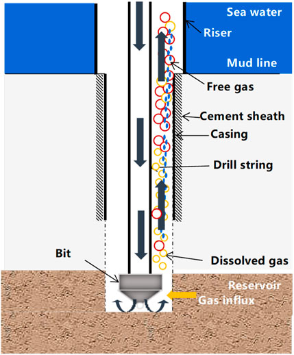
FIGURE 1. Schematic diagram of physical model after gas influx in MPD.
This paper establishes a pressure wave propagation model for the process of pressure wave propagation formed by the added backpressure in step (4). The main assumptions include:
(1) The fluid in wellbore and wellbore wall are in a thermal equilibrium state;
(2) There is no heat exchange between gas and liquid;
(3) There is a mass exchange between gas and liquid;
(4) The pressure wave formed by backpressure propagates one-dimensional along the wellbore axis.
The control volumes of gas and liquid phases are taken out separately and then mass conservation equations are established, as shown in Eq. 1.
where A means area of annulus, m2;
The momentum conservation equations for gas and liquid phases are as follows:
where P is the annulus pressure, Pa; F represents the external force acting on the fluid.
(1) Gas influx rate
During the MPD process, once the bottom hole pressure is lower than the reservoir pressure, the reservoir gas would flow into the annulus in a negative pressure manner. The flow of reservoir gas into the annulus can be treated as a plane radial flow of an infinite formation flowing towards a point, which can be described by the following model, as shown in Eq. 3 (NygaardVefringFjelde et al., 2007):
where Pk is the bottomhole pressure when gas influx occurs, Pa; Pe means the reservoir pressure, Pa;
The open hole section of wellbore can be divided into n part, the length of every part is
(2) Gas-liquid inter-phase mass transfer rate induced by gas dissolution
(3) Properties of gas
Gas density is calculated with the real gas state equation, as shown in Eq. 7.
where
where A1∼A8 are the coefficients;
The gas viscosity can be calculated using the following equations (Eq. 9–Eq. 12).
where
(4) Gas-liquid interfacial resistance
The external force acting on the gas phase is shown in Eq. 13.
The external force acting on the liquid phase is shown in Eq. 14.
where
where
where,
The mass conservation equations, momentum conservation equations, and auxiliary equations form a gas-liquid two-phase dual fluid model. Based on this model, the propagation velocity of pressure wave in gas-liquid two-phase flow is derived.
The partial differential components in the above equations are expanded into partial differential forms with V= (
The eigenvalues of the coefficient matrix (
In gas-liquid two-phase flow, both gas and water are considered as continuous media. The propagation velocity of pressure waves in each phase of the fluid can be described by the following equation:
The pressure wave velocity of two-phase flow considering gas-liquid mass transfer can be obtained by solving the following determinant:
The steps for solving the propagation velocity of pressure wave at various positions in the wellbore in gas-liquid two-phase flow are as follows:
(1) Input basic parameters, boundary conditions, and initial conditions;
(2) Divide grids to solve the multi-phase flow model of gas invasion in marine pressure controlled drilling;
(3) Obtain parameters such as pressure, void fraction, gas phase density, and liquid phase density of each spatial node at that time;
(4) Solve the semi implicit equation of pressure wave propagation velocity in a dual fluid model considering gas-liquid mass transfer;
(5) Solve the pressure wave velocity of each spatial node at that time;
(6) Solve all time pressure wave velocities.
The reliability of the pressure wave propagation velocity model established in this paper is verified through experimental data. It is very difficult to directly measure the pressure wave velocity transmitted in the gas-liquid two-phase flow of the wellbore during drilling operations. Therefore, the pressure wave velocity measured in vertical gas-liquid two-phase pipe flow experiments by Henry et al. was used to validate the model. Henry et al. used a 2-inch diameter vertical stainless steel tube in their experiment to test the pressure wave velocity in a stable bubble flow with a gas volume fraction less than 40% (Henry et al., 1971).
As shown in Figure 2, the comparison results show that the error between the calculated pressure wave propagation velocity of model in this paper and the experimental data is within 15% with 6% average error. Thus, the accuracy of the pressure wave velocity model in this article is considered acceptable for wave velocity calculation in drilling engineering.
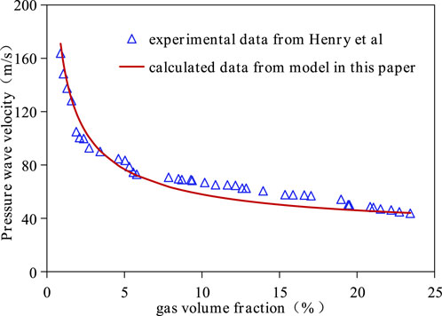
FIGURE 2. Comparison between the calculated results of the pressure wave velocity model in this paper and experimental results.
The distribution of pressure wave propagation velocity at each stage of gas invasion was calculated and analyzed with a directional well as the target well. The influence of drilling fluid type, drilling fluid density and backpressure on the propagation velocity of pressure wave were investigated. Then the mechanism are explained. The specific parameters of this directional well are shown in Table 1.
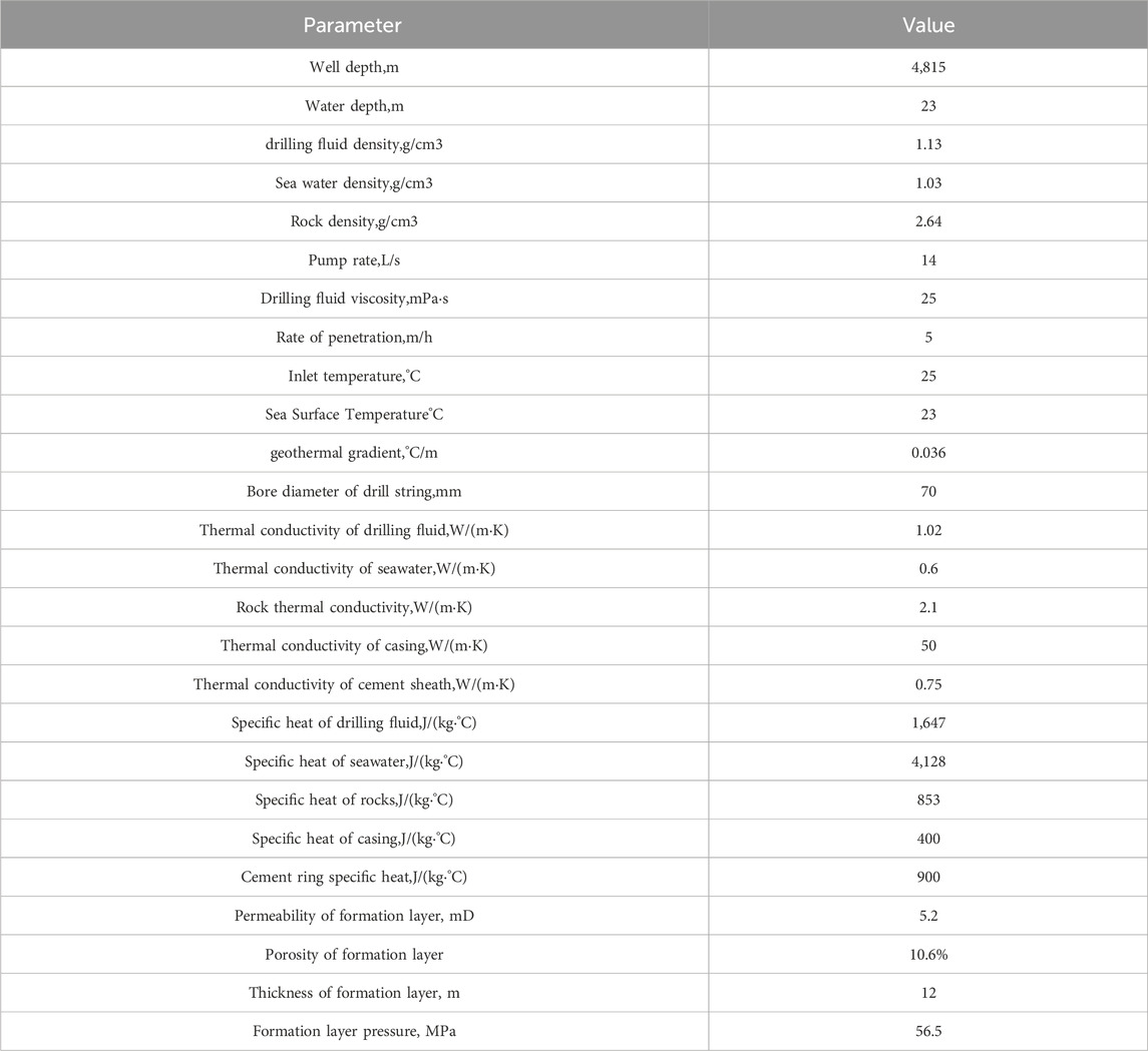
TABLE 1. Parameter and values used in calculation.
In this subsection, the propagation characteristics of pressure waves at different stages of gas invasion are investigated. Oil based drilling fluid with a density of 1.13 g/cm3 was used, and the difference between bottom hole pressure and formation pressure is set to 0.3 MPa. The invading gas in this paper is 100% pure methane with a density of 0.64 g/cm3. To thoroughly investigate the propagation characteristics of pressure waves in different states of gas invasion, the pit gains of 1 m3, 2 m3, 5 m3 and 10 m3 in this section. It must be noted that this assumed degree of gas invasion in this study is significant. In fact, if the a degree of gas invasion is that significant during the drilling process, this well would be shut down instead of continuing to use the MPD technology. The pressure wave velocity distributions at pit gain of 1 m3, 2 m3, 5 m3 and 10 m3 are calculated and compared.
Figure 3 shows the comparison of pressure wave velocity distributions when pit gains are 1 m3, 2 m3, 5 m3 and 10 m3. As described in Figure 3, the distributions of pressure wave propagation velocity along the wellbore are similar when the pit gain are is 1 m3, 2 m3, and 5 m3. The propagation velocity under these three gas invasion stages above 4,749 m are the same and relatively high. Below 4,749 m, propagation velocities are decreased by the increment of the pit gain. The distribution of pressure wave propagation velocity with a pit gain of 10 m3 is significantly different from these three stages. The low pressure wave propagation velocity length of 10 m3 pit gain is 1,135 m which is highly longer than 50 m of 1 m3, 2 m3, and 5 m3. The times required for pressure wave to propagate from the wellhead to the bottom of the well at these four gas invasion stages has been calculated. Results of times required are 4.3 s, 4.3 s, 4.4 s and 21.8 s, respectively. It can be seen that the time required for pressure waves to propagate in the wellbore changes relatively little under 1 m3, 2 m3, and 5 m3 pit gain. However, the propagation of pressure waves in the wellbore takes a longer propagation time under 10 m3 pit gain. The pressure wave propagates to the bottom of the well to restrain gas invasion, which cannot be completed instantaneously. This indicates that the propagation delay effect of pressure wave must be considered in wellhead back pressure design during well killing stage.
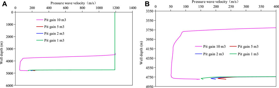
FIGURE 3. Comparison of pressure wave propagation velocities in different stages of gas invasion: (A) Distribution of pressure wave velocity throughout the wellbore; (B) Enlarged diagram of pressure wave velocity distribution in the lower part of the wellbore.
Figure 4 shows the comparison of free gas volume fraction at different gas invasion stage. As depicted in Figure 4, the free gas volume fraction near the bottom of the well increases significantly in the later stage of gas invasion, which is the main reason for the decrease in pressure wave propagation velocity. Due to the ability of oil-based drilling fluids to dissolve gas invading the wellbore, the propagation velocity of pressure waves is less affected by the invading gas under 1 m3, 2 m3, and 5 m3 pit gain. When the gas invasion is small, the gas can dissolve into oil-based drilling fluid through gas-liquid mass transfer. The free gas content in the wellbore is small, and the propagation process of pressure waves in the wellbore is mostly through single-phase liquid. The propagation velocity of pressure waves is relatively high, and the required time is short. As the amount of gas invasion increases, such as the mud pit increment reaches 10 m3, the gas-liquid mass transfer process of the drilling fluid reaches equilibrium, and the dissolution of the drilling fluid is saturated. Therefore, the gas in the drilling fluid becomes more and more abundant. The mass transfer between the gas and liquid phases in the wellbore becomes increasingly strong until it reaches stability. Therefore, an increasing number of gas exists in the form of free gas and reduces the propagation speed of pressure waves.
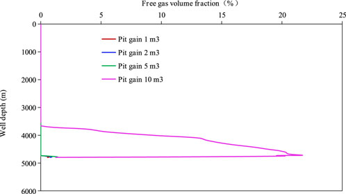
FIGURE 4. Comparison of free gas volume fraction at different gas invasion stage.
According to the calculation results and analysis in this section, the control strategy of wellbore pressure in MPD technology needs to be continuously adjusted according to the gas invasion state. The smaller the gas invasion, the earlier it is discovered, and the faster the response of wellbore pressure. The response time of wellbore pressure in the later stage of invasion needs to be calculated based on the gas invasion situation.
In this subsection, the influence of drilling fluid type on pressure wave velocity is investigated. The propagation velocities of pressure wave at different positions in the wellbore under two different drilling fluid are calculated and compared. Figure 5 shows the comparison of pressure wave velocities between water based drilling fluid and oil based drilling fluid when the pit gain is 1 m3. The oil-water ratio of oil-based drilling fluid used in this part is 100:0, while the oil-water ratio of water-based drilling is 0:100.
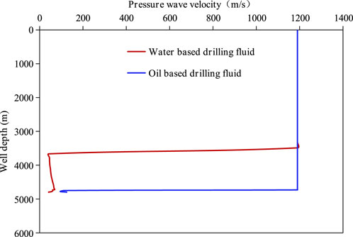
FIGURE 5. Comparison of pressure wave velocities between water based drilling fluid and oil based drilling fluid.
As shown in Figure 5, the propagation velocity of pressure wave is unevenly distributed at various positions in the wellbore. The propagation velocity of pressure wave in the upper part of the wellbore is relatively high, while the propagation velocity of pressure wave in the lower part of the wellbore is relatively low. In the case of oil-based drilling fluid, from the bottom of well to wellhead, the propagation velocity of pressure wave first decreases from 124.8 m/s to 95.1 m/s, then increases to 113.6 m/s, and then remains at 1,190 m/s. While in the case of water-based drilling fluid, from the bottom of well to wellhead, the propagation velocities of pressure waves increase from 41.7 m/s to 69.5 m/s, and then decrease to 44.4 m/s, and then remains at 1,190 m/s. As indicated by Figure 5, the location of the minimum propagation velocity of wellbore pressure wave in the case of oil-based drilling fluid and water-based drilling fluid is 20 m and 1,135 m away from the bottom of the well respectively.
The influence of drilling fluid type on the propagation velocity of pressure wave is due to the influence of the existing form of invading gas in the wellbore. As shown in Figure 6, in gas-liquid two-phase fluid, the increase of free gas volume fraction would reduce the propagation velocity of pressure wave. In oil-based drilling fluids, most of the invading gases exist in the drilling fluid in liquid form due to the mass transfer between gas and liquid phases. On the contrary, in water-based drilling fluid, there is no inter-phase mass transfer behavior between the invading gas and the drilling fluid. The invading gas exists in the form of free gas, which greatly reduces the propagation speed of pressure waves in gas-liquid two-phase fluid. The distribution of free gas volume fraction in the annulus under two types of drilling fluids is calculated and shown in Figure 6.
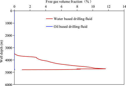
FIGURE 6. Comparison of free gas volume fraction between oil based drilling fluid and water based drilling fluid.
Figure 6 shows the comparison of free gas volume fractions in annulus between oil-based and water-based drilling fluids when pit gain is 1 m3. As shown in Figure 6, the free gas volume fraction in the annulus of oil-based drilling fluid is basically close to zero, while the free gas volume fraction in water-based drilling fluid is high. The free gas volume fraction in the annulus of water-based drilling fluid is unevenly distributed. From the bottom to the wellhead, the free gas volume fraction increases from 1% to 11.4%, and then decreases to 0%. The maximum free gas volume fraction is located 78.5 m away from the bottom of the well. The form of invading gas in the annulus has an impact on the density of the annulus mixture. To analyze the effect of annular mixture density on pressure wave propagation velocity, the dissolved gas mass fraction and mud density distribution of annular mixture under two types of drilling fluids are calculated and displayed in Figure 7.
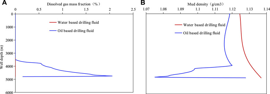
FIGURE 7. Comparison of dissolved gas mass fraction and mud density in annulus between oil based drilling fluid and water based drilling fluid: (A) Distribution of gas mass fraction; (B) Distribution of mud density.
Figure 7 shows the comparison of dissolved gas mass fraction mud density in annulus between oil-based and water-based drilling fluids when the pit gain is 1 m3. As depicted in Figure 7, the mass fraction of dissolved gas in the annulus is 0 in the case of water-based drilling fluid, while in the case of oil-based drilling fluid, the dissolved gas mass fraction in the annulus are relatively high. From the bottom of the well, the dissolved gas mass fraction increases from 0.16% to 2.1%, and then decreases to 0. The maximum position of the dissolved gas mass fraction is 50.4 m from the bottom of the well. From the bottom of the well, the density of oil-based drilling fluid decrease from 1.130 g/cm3 to 1.075 g/cm3, then increased to 1.2 g/cm3, then decreased upwards to 1.115 g/cm3, and finally increased to 1.118 g/cm3. Combining Figures 7A, B, dissolved gas mass fraction reduces the density of oil-based drilling fluid. Based on the comprehensive analysis of Figures 5–7, it can be concluded that the influence of drilling fluid type on the propagation velocity of pressure wave is mainly controlled by the free gas volume fraction, while the influence of annular mud density is relatively small. The response time to wellbore pressure after water based drilling fluid gas invasion is longer. This makes it more difficult to regulate the pressure of water-based drilling fluid after gas invasion than oil-based drilling fluid.
In this subsection, the influence of drilling fluid density on the propagation velocity of pressure waves is studied. The drilling fluid type is oil-based with different fluid density. The propagation velocities of pressure waves in annulus at 200 s of gas invasion under three different drilling fluid densities are calculated and compared.
Figure 8 shows the comparison of pressure wave propagation velocity distribution after 200 s of gas invasion at drilling fluid densities of 1.11 g/cm3, 1.13 g/cm3, and 1.15 g/cm3. As depicted in Figure 8, after gas invasion for 200 s the pressure wave velocity above the well depth of 4,731 m under three different drilling fluid densities are greater than that below 4,731 m. Moreover, the propagation velocities of pressure wave below 4,731 m at a density of 1.15 g/cm3 is greater than that at densities of 1.11 g/cm3 and 1.13 g/cm3. To illustrate the mechanism of the influence of drilling fluid density on the propagation velocity of pressure wave, the distribution of free gas volume fraction in the annulus under three different drilling fluid densities is calculated and displayed in Figure 9.
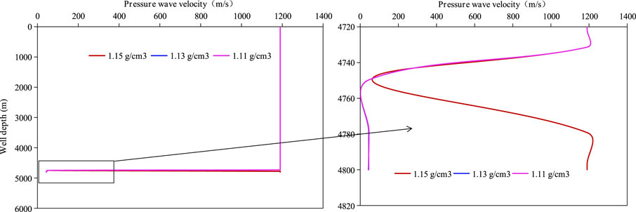
FIGURE 8. Pressure wave propagation velocity under different drilling fluid densities.
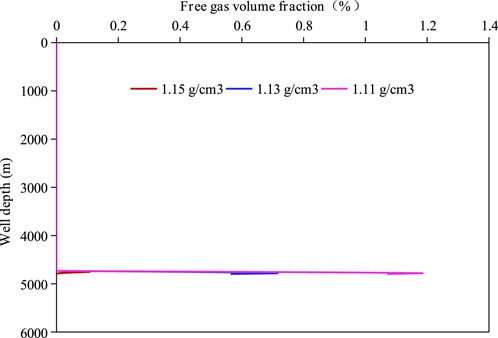
FIGURE 9. Free gas volume fraction under different drilling fluid densities.
As shown in Figure 9, the distribution characteristics of free gas volume fraction in the annulus vary under different drilling fluid densities. The free gas volume fraction is unevenly distributed along the wellbore under three different drilling fluid densities. There is a peak free gas volume fraction at the bottom of the wellbore. The increase in drilling fluid density can reduce the peak value of free gas volume fraction at the bottom of the wellbore. This is mainly due to the fact that high drilling fluid density can suppress gas invasion and reduce the volume of gas invading the wellbore. In addition, high drilling fluid density can also enhance mass transfer between gas-liquid phases, thereby reducing the volume fraction of free gas. It can be concluded that under high drilling fluid density, the response and control time for wellhead backpressure are shorter than those of low drilling fluid density.
In this subsection, the propagation velocity of wellbore pressure wave under different backpressure values are calculated and compared to investigate the Influence of backpressure value on the pressure wave velocity.
Figure 10 shows the distribution of pressure wave propagation velocity at 300 s, 600 s, 900 s, and 1,200 s after the occurrence of gas invasion under 0.2 MPa and 0.5 MPa backpressure. As depicted in Figure 10, when a gas invasion occurs for 300 s, there is little difference in the distribution of pressure wave propagation velocity between 0.2 MPa and 0.5 MPa backpressure. In both cases, the propagation velocity of pressure wave near the bottom of the well is low due to the presence of free gas, while the propagation velocity of pressure wave at the upper position is high. Comparing the four figures in Figure 10, the length of the low pressure wave propagation velocity region near the wellbore increases over time. This is because gas invaded into wellbore increases with time, and it is transported from wellbore to wellhead with circulated drilling fluid. Compared with 0.2 MPa backpressure case, the wellbore length with lower pressure wave propagation velocity under 0.5 MPa backpressure is significantly shorter. The reason behind this phenomena is that high backpressure can effectively restrain the velocity of gas invasion into the wellbore, and therefore reduce free gas volume fraction in the annulus.
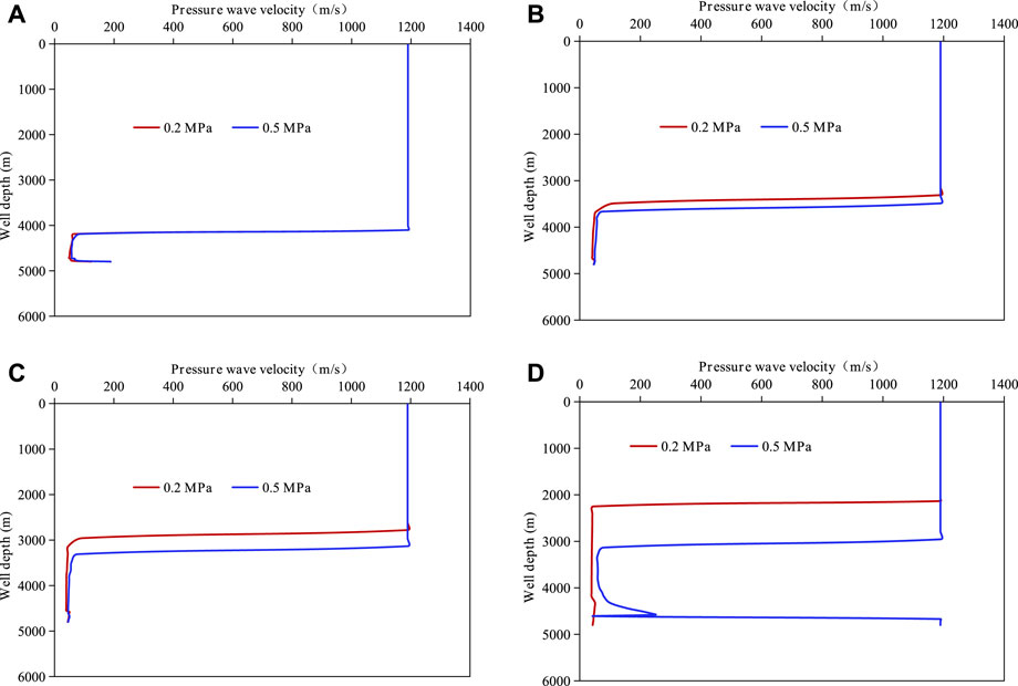
FIGURE 10. Propagation velocity of pressure waves at various positions in the wellbore under different gas invasion stage: (A) 300 s; (B) 600 s; (C) 900 s; (D) 1,200 s.
Figure 11 shows the comparison of time required for pressure waves to propagate from the wellhead to the bottom of the well under different backpressure values. As depicted in Figure 11, the propagation time of pressure waves under 0.2 MPa is greater than that under 0.5 MPa, and the difference between these two cases increase with the increase of gas invasion time. The difference between these two cases increases from 1.38 s at gas invasion 300 s–37.93 s at gas invasion 1,200 s. This also indicates that the propagation time of pressure waves should be considered in the design of wellhead backpressure values in MPD technology. The propagation time of pressure wave at 1,200 s under 0.5 MPa backpressure is lower than that at 900 s. This is because that the gas invasion under 0.5 MPa is controlled properly and the gas invasin is stopped. At the same time, a part of the invasion gas has been transported out at 1,200 s. Therefore, the amount of free gas at 1,200 s is smaller than that at 900 s.
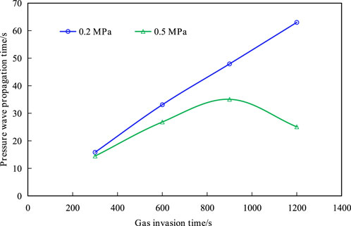
FIGURE 11. Pressure wave propagation time under different gas invasion stage.
A new model has been established to investigate the propagation velocity of pressure waves in multiphase flow with gas-liquid mass transfer phenomena, and it has been proved reliable with experimental data in literature. The propagation characteristic of pressure wave in a real well is investigated and illustrated. Based on the obtained results, the following conclusions can be drawn.
(1) The propagation of pressure wave induced by backpressure from the wellhead to the bottom of the well is not instantaneous, and the time required for this process increases with the gas invasion time. Therefore, this time should not be ignored in the design of wellhead backpressure parameters for MPD.
(2) For oil-based drilling fluid, due to the mass transfer between invasion gas and drilling fluid, the free gas volume fraction in the drilling fluid is relatively low, and the propagation velocity of pressure wave is relatively high. While for water-based drilling fluid, since there is no mass transfer between gas and drilling fluid, the volume fraction of free gas and the propagation velocity of pressure waves are exactly the opposite.
(3) The influence of drilling fluid density and wellhead backpressure on the propagation behavior of pressure waves is mainly due to the fact that high drilling fluid density and high wellhead backpressure could suppress the occurrence of gas invasion. Then the volume fraction of free gas in the wellbore is reduced, which leads to an increase of pressure wave propagation velocity. The conclusion of this article can provide guidance on the propagation characteristics of pressure waves in multiphase flow and lay a foundation for the design of MPD parameters.
The raw data supporting the conclusion of this article will be made available by the authors, without undue reservation.
YH: Methodology, Writing–original draft. ZL: Project administration, Supervision, Writing–review and editing. ZY: Resources, Validation, Writing–review and editing. BF: Resources, Supervision, Writing–review and editing. YM: Resources, Supervision, Writing–review and editing. XY: Resources, Validation, Writing–review and editing. DT: Formal Analysis, Methodology, Writing–original draft. WC: Formal Analysis, Methodology, Writing–review and editing. MR: Methodology, Validation, Writing–review and editing. XZ: Data curation, Methodology, Validation, Writing–review and editing.
The author(s) declare financial support was received for the research, authorship, and/or publication of this article. This work is supported by the China Postdoctoral Science Foundation (No. 2023M743922) and the National Natural Science Foundation of China (No. 52274026).
Authors YH, ZL, ZY, YM, XY, DT, WC, MR, and XZ were employed by CNOOC Research Institute Ltd. Author BF was employed by CNOOC China Limited.
All claims expressed in this article are solely those of the authors and do not necessarily represent those of their affiliated organizations, or those of the publisher, the editors and the reviewers. Any product that may be evaluated in this article, or claim that may be made by its manufacturer, is not guaranteed or endorsed by the publisher.
Bai, B., Huang, F., Guo, L., and Wang, X. (2005). Propagation of pressure wave for bubbly flow in vertical upward tube. Nucl. Power Eng. 26 (4), 323–326.
Campbell, I. J., and Pitcher, A. S. (1958). Shock waves in a liquid containing gas bubbles. Proceedings of the Royal Society of London. Series A. Math. Phys. Sci. 243 (1235), 534–545. doi:10.1098/rspa.1958.0018
Carstensen, E. L., and Flody, L. L. (1947). Propagation of sound through a liquid containing bubbles. J. Acoust. Soc. Am. 19 (3), 481–501. doi:10.1121/1.1916508
Chen, X., He, M., Xu, M., Wang, S., and Dai, B. (2023). Early gas kick detection-inversion-control integrated system: the significance of applications of managed pressure drilling: a review. Geoenergy Sci. Eng. 229, 212134. 212134. doi:10.1016/j.geoen.2023.212134
Falk, K. (1998). “Rapid pressure waves trough gas-liquid flow in wells and pipelines,” in SPE Europec featured at EAGE Conference and Exhibition, The Hague, Netherlands, October, 1998.
Fang, L., Meng, L., Liu, C., and Yuxing, L. (2021). Experimental study on the amplitude characteristics and propagation velocity of dynamic pressure wave for the leakage of gas-liquid two-phase intermittent flow in pipelines. Int. J. Press. Vessels Pip. 193, 104457. 104457. doi:10.1016/j.ijpvp.2021.104457
Henry, R. E., Grolmes, M. A., and Fauske, H. K. (1971). Pressure-pulse propagation in two-phase one- and two-component mixtures. Lemont, IL, United States: Argonne National Lab.
Hou, Y., Peng, Y., Chen, Z., Liu, Y., Zhang, G., Ma, Z., et al. (2021). Investigation on the controlling factors of pressure wave propagation behavior induced by pulsating hydraulic fracturing. SPE J. 26 (05), 2716–2735. doi:10.2118/205384-pa
Hsieh, D. Y., and Plesset, M. S. (1961). On the propagation of sound in a liquid containing gas bubbles. Phys. fluids 4 (8), 970–975. doi:10.1063/1.1706447
Huang, F., Bai, B., and Guo, L. (2004). A mathematical model and numerical simulation of pressure wave in horizontal gas-liquid bubbly flow. Prog. Nat. Sci. 14 (4), 344–349. doi:10.1080/10020070412331343591
Huang, F., Takahashi, M., and Guo, L. (2005). Pressure wave propagation in air-water bubbly and slug flow. Prog. Nucl. Energy 47 (1-4), 648–655. doi:10.1016/j.pnucene.2005.05.068
Kaidarov, A., Magda, A., Samarin, A., Aliyev, F., and Kazakbayeva, Z. (2022). “Managed pressure drilling and managed pressure cementing: first successful implementation of advanced Technologies for unique wells with constant inflow in slim drill Project,” in SPE Annual Caspian Technical Conference, Astana, Kazakhstan, November, 2022. 212108.
Legius, H., Van den Akker, H. E. A., and Narumo, T. (1997). Measurements on wave propagation and bubble and slug velocities in cocurrent upward two-phase flow. Exp. Therm. Fluid Sci. 15 (3), 267–278. doi:10.1016/s0894-1777(97)00012-5
Li, H., Chen, R., Li, X., Meng, Y., Zhu, L., and Zhao, J. (2016). Investigation of pressure wave propagation and attenuation characteristics in wellbore gas-liquid two-phase flow. J. Nat. Gas Sci. Eng. 35, 1088–1100. doi:10.1016/j.jngse.2016.09.020
Li, X., Zhang, J., Tang, X., Li, B., Wang, Y., and Zhao, Z. (2022). Propagation characteristics and application effects of measurement-while-drilling pressure wave for early gas-kick detection. J. Loss Prev. Process Industries 76, 104741. 104741. doi:10.1016/j.jlp.2022.104741
Li, Y., Li, C., Chen, E., and Ying, Y. (2011). Pressure wave propagation characteristics in a two-phase flow pipeline for liquid-propellant rocket. Aerosp. Sci. Technol. 15 (6), 453–464. doi:10.1016/j.ast.2010.09.011
Lin, Y., Kong, X., Qiu, Y., and Yuan, Q. (2013). Calculation analysis of pressure wave velocity in gas and drilling mud two-phase fluid in annulus during drilling operations. Math. Problems Eng. 2013 (17), 1–17. 318912. doi:10.1155/2013/318912
Liu, X., Li, B., and Yue, Y. (2007). Transmission behavior of mud-pressure pulse along well bore. J. Hydrodynamics 19 (2), 236–240. doi:10.1016/s1001-6058(07)60054-7
Miyazaki, K., Fujii-e, Y., and Suita, T. (1971). Propagation of pressure wave in air-water two-phase system,(II). J. Nucl. Sci. Technol. 8 (12), 673–681. doi:10.1080/18811248.1971.9733020
Mori, Y., Hijikata, K., and Komine, A. (1975). Propagation of pressure waves in two-phase flow. Int. J. Multiph. Flow 2 (2), 139–152. doi:10.1016/0301-9322(75)90004-x
Najjarpour, M., Jalalifar, H., and Norouzi-Apourvari, S. (2022). Fifty years of experience in rate of penetration management: managed pressure drilling technology, mechanical specific energy concept, bit management approach and expert systems-A review. J. Petroleum Sci. Eng. 208, 109184. 109184. doi:10.1016/j.petrol.2021.109184
Nguyen, D. L., Winter, E. R. F., and Greiner, M. (1981). Sonic velocity in two-phase systems. Int. J. Multiph. Flow 7 (3), 311–320. doi:10.1016/0301-9322(81)90024-0
NygaardVefringFjelde, G. H. E. H. K. K., Nævdal, G., Lorentzen, R. J., and Mylvaganam, S. (2007). Bottomhole pressure control during drilling operations in gas-dominant wells. Spe J. 12 (01), 49–61. doi:10.2118/91578-PA
Ruggles, A. E., Lahey, R. T., Drew, D. A., and Scarton, H. A. (1988). An investigation of the propagation of pressure perturbations in bubbly air/water flows. J. Heat Transf. 110 (2), 494–499. doi:10.1115/1.3250513
Sheikhi, M. A., Nikoofard, A., and Khaki-Sedigh, A. (2022). Control of managed pressure drilling systems using nonlinear predictive generalized minimum variance approach based on a Volterra model. ISA Trans. 128, 380–390. doi:10.1016/j.isatra.2021.11.022
Wang, H., Priestman, G. H., Beck, S. B. M., and Boucher, R. (2000). Measurement and simulation of pressure wave attenuation in upward air–water bubbly flow. Int. J. heat fluid flow 21 (1), 104–111. doi:10.1016/s0142-727x(99)00052-1
Wang, J., Deng, S., Li, J., Yang, H., and Liu, G. (2023). Development of a multiphase variable mass flow model and its application in well control for variable gradient managed pressure drilling. Energy Rep. 9, 3358–3368. doi:10.1016/j.egyr.2023.02.026
Wijngaarden, L. (1972). One-dimensional flow of liquids containing small gas bubbles. Annu. Rev. fluid Mech. 4 (1), 369–396. doi:10.1146/annurev.fl.04.010172.002101
Xue, Y., Yue, L., Ding, R., Zhu, S., Liu, C., and Li, Y. (2023). Influencing mechanisms of gas bubbles on propagation characteristics of leakage acoustic waves in gas-liquid two-phase flow. Ocean. Eng. 273, 114027. 114027. doi:10.1016/j.oceaneng.2023.114027
Yang, H. W., Li, J., Jiang, J. W., Zhang, H., Guo, B. Y., Zhang, G., et al. (2022). A dynamic managed pressure well-control method for rapid treatment of gas kick in deepwater managed pressure drilling. Petroleum Sci. 19 (5), 2297–2313. doi:10.1016/j.petsci.2022.06.011
Zhang, H., Umehara, Y., Yoshida, H., and Mori, S. (2023). On the velocity and frequency of disturbance waves in vertical annular flow with different surface tension and gas–liquid density ratio. Int. J. Heat Mass Transf. 211, 124253. 124253. doi:10.1016/j.ijheatmasstransfer.2023.124253
Keywords: managed pressure drilling, wellbore flow, gas liquid flow, pressure wave, propagation characteristic
Citation: Hou Y, Li Z, Yin Z, Fan B, Ma Y, Yang X, Tian D, Cai W, Ren M and Zhang X (2024) Investigation on the propagation characteristics of pressure wave during managed pressure drilling. Front. Energy Res. 12:1364791. doi: 10.3389/fenrg.2024.1364791
Received: 03 January 2024; Accepted: 24 January 2024;
Published: 23 February 2024.
Edited by:
Feng Dong, China University of Geosciences, ChinaReviewed by:
Xiangji Dou, Changzhou University, ChinaCopyright © 2024 Hou, Li, Yin, Fan, Ma, Yang, Tian, Cai, Ren and Zhang. This is an open-access article distributed under the terms of the Creative Commons Attribution License (CC BY). The use, distribution or reproduction in other forums is permitted, provided the original author(s) and the copyright owner(s) are credited and that the original publication in this journal is cited, in accordance with accepted academic practice. No use, distribution or reproduction is permitted which does not comply with these terms.
*Correspondence: Zhiming Yin, eWluemhtQGNub29jLmNvbS5jbg==
†These authors have contributed equally to this work and share first authorship
Disclaimer: All claims expressed in this article are solely those of the authors and do not necessarily represent those of their affiliated organizations, or those of the publisher, the editors and the reviewers. Any product that may be evaluated in this article or claim that may be made by its manufacturer is not guaranteed or endorsed by the publisher.
Research integrity at Frontiers
Learn more about the work of our research integrity team to safeguard the quality of each article we publish.