 Fengzhang Luo
 Xuan Wu
 Zhe Wang2
95% of researchers rate our articles as excellent or good
Learn more about the work of our research integrity team to safeguard the quality of each article we publish.
Find out more
METHODS article
Front. Energy Res. , 26 June 2024
Sec. Smart Grids
Volume 12 - 2024 | https://doi.org/10.3389/fenrg.2024.1361559
This article is part of the Research Topic Power System Operation and Optimization Considering High Penetration of Renewable Energy View all 26 articles
The snow-shaped distribution network (SDN) is a cable distribution network composed of eight (or six) 10 kV feeders from four (or three) substations in a regular connection. Compared with the traditional 10 kV distribution network, SDN can support a wide range of load transfer among six or eight feeders. Aiming at the problem of load spatial-temporal unbalanced condition caused by the integration of distributed generators (DGs) and different load types in different feeders, this paper proposes a dynamic reconfiguration strategy for load balancing in SDN considering DGs and energy storage system (ESS). Firstly, the basic structure of SDN is analyzed and the power flow model for its dynamic reconfiguration is developed. Secondly, the dynamic reconfiguration optimization model for load balancing in SDN considering DGs and ESS is proposed to utilize the load transfer capability to mitigate the load unbalanced condition and reduce active power loss. Thirdly, the original non-convex model is converted into a mixed-integer second-order cone programming (MISOCP) model by applying the second-order cone relaxation and the big-M method, which is solved by CPLEX solver. Finally, the effectiveness of the proposed model and method are verified by an actual case in Tianjin and IEEE 33-node system. The analysis results show that the proposed method can significantly alleviate the load unbalanced spatial-temporal distribution and improve the economic efficiency by regulating the operation of SDN including ESS optimization and dynamic reconfiguration.
The distribution system is the final link in the power system, directly serving the majority of users, and being closely related to population distribution and economic development. With the high-permeability access of DGs and the uneven spatial distribution of industrial, commercial, and residential regions in urban areas, the problem of load unbalanced spatial-temporal distribution has always existed in urban distribution networks. The mismatch between power generation and consumption may cause lower resource utilization, network congestion (Zhao et al., 2022), and increased active power loss, which seriously affects the security and economy of distribution network.
Aiming at the problem of load spatial-temporal unbalanced condition, there are mainly the following solutions. One option is to consider new substations or line expansion (Yao et al., 2014), but this involves high investment costs and is challenging to implement, especially in areas with limited urban land resources. Through flexible regulation of controllable resources such as energy storage devices and flexible load, load curves can be dynamically adjusted by peak shaving and valley filling to alleviate load imbalance and other problems (Cho et al., 2012; Hosseina and Bathaee, 2016; Li et al., 2022). The effectiveness of this method is affected by the capacity and location of controllable resources. Network topology reconfiguration involves altering the open and closed states of switches in the feeders to balance feeder load, adjust power flow distribution, and improve the economic efficiency of distribution network (Baran and Wu, 1989a; Ji, 1997). Generally, distribution network reconfiguration can be divided into two categories: static reconfiguration and dynamic reconfiguration. Static reconfiguration optimizes the topology of the distribution network under a single time section, which is the basis of dynamic reconfiguration. Dynamic reconfiguration takes into consideration the fluctuation of DGs and load demand to dynamically optimize the distribution network structure in a continuous period (Jabr et al., 2012). The optimization objectives for distribution network reconfiguration are usually to minimize the active power loss (Jakus et al., 2017), improve the system reliability (Lotfi et al., 2020) and voltage stability (Zhang and Wang, 2004; Wang, 2012), and balance the feeder load (Gao et al., 2022). The optimization problem in multi-time dynamic reconfiguration involves both continuous and numerous discrete variables, posing a challenging task. Mathematical optimization methods (López et al., 2016; Tian et al., 2016; Aldik and Venkatesh, 2020), intelligent optimization algorithm (Lotfi and Ghazi, 2021; Lotfi, 2022) and heuristic algorithms (Jakus et al., 2020; Silveira et al., 2021; Montoya et al., 2023; Yu et al., 2023) have been proposed to solve the problem. Heuristic algorithms, not necessitating convexity in the mathematical model, have been widely used in solving non-convex problems. However, the results may be local optimal solutions through heuristic algorithms. With the development of optimization theory, mathematical optimization methods have been extensively applied to solve dynamic reconfiguration problems. Specifically, the convex relaxation technique represented by second-order cone programming (SOCP) is used more and more frequently, which can obtain the globally optimal solution and reduce the computation time.
The above studies address the distribution network load balancing problem with traditional single-radial distribution network, most of them start from the spatial dimension to realize load balancing by adjusting the tie switches state. The dispatching means are relatively single, considered only from the feeder level, with less consideration of scenarios where load and DG output change over time, and seldom with the main objective of load balancing of multiple feeders in multiple substations. However, relative to the previous grid structure, snow-shaped distribution network is upgraded based on a 10 kV single-double ring network by adding new station tie switches. The snow-shaped distribution network (SDN) (Wang et al., 2023) constructs a “3-station 6-wire” or “4-station 8-wire” feeder cluster, with the ring main units as the network unit, and each feeder contains multiple tie switches and segment switches. The flexible and controllable ring network structure of SDN establishes a supportive platform for dynamic reconfiguration to achieve multi-level and multi-directional load transfer, and provides an effective means to promote the spatial-temporal balance of load within feeder clusters. It can comprehensively consider a variety of control means to realize the load transfer between two feeders supplied by the same transformer, different transformers, and different substations, to achieve the “feeder-transformer-substation” three levels of load balancing.
To our best knowledge, this is the first study on the load imbalance problem of substation level, transformer level and feeder level in urban SDN. From both time and space dimension, this paper proposes a multi-objective dynamic reconfiguration model for load balancing through collaborative optimal dispatching of dynamic reconfiguration and distributed energy storage system in SDN. Firstly, the grid structure of SDN is analyzed and the power flow model for its dynamic reconfiguration is developed. Secondly, based on the advantages of multiple inter-station and intra-station connections, a dynamic reconfiguration model in SDN for feeder load balancing is established, considering DGs and ESS. In order to take into account the economic efficiency and load balancing, the weighted combination of the minimum active power loss and load balance index is proposed as the optimization objective function. Thirdly, the original non-convex model is converted into a mixed-integer second-order cone programming (MISOCP) model using convex relaxation theory for an accurate and efficient solution. Finally, the proposed dynamic reconfiguration model and method are analyzed and verified in the 10 kV Tianjin snow-shaped distribution network and IEEE 33-node system.
Under the development of new power distribution system, a flexible and controllable ring network structure named SDN is proposed in Wang et al. (2023), based on the traditional single and double ring distribution network. This structure comprehensively supports the wide range of load transfers between different feeders, feeder clusters, and snow-shaped units.
SDN takes the ring main units as ring network nodes, composed of eight (or six) 10 kV feeders from four (or three) substations in a regular connection to form a group of independent feeder clusters. Each substation has two 10 kV outgoing lines, each equipped with an inter-station contact and an intra-station contact. As shown in Figure 1, taking the four-station SDN as an example, the existing four groups of single-loop network wiring only establish contacts between the stations. Building on this foundation, four new intra-station contacts have been added, so that the inter-station and intra-station have established load transfer channels to provide an effective method for spatial-temporal load balancing in the feeder cluster.
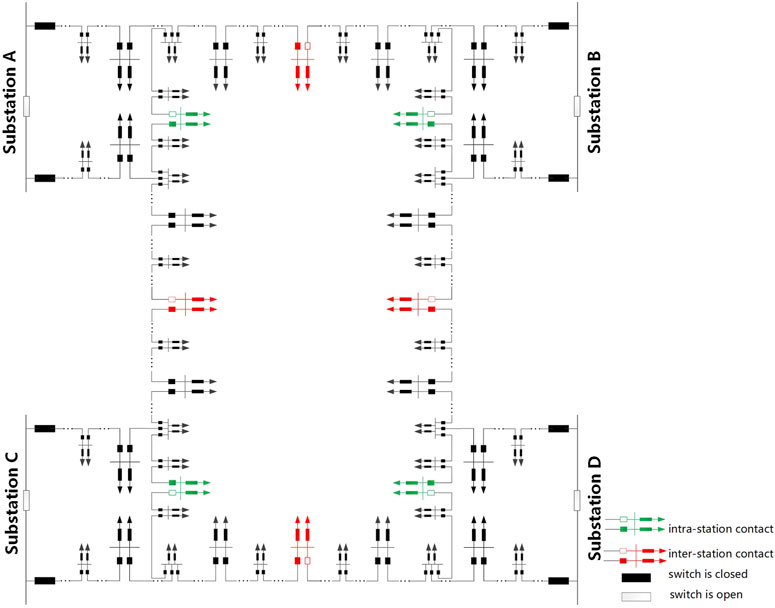
Figure 1. Schematic diagram of a 4-station, 8-wire snowflake distribution network.
In this paper, the branch power flow model for SDN dynamic reconfiguration is developed based on the distflow model which was proposed in Baran and Wu (1989b). This paper introduced 0–1 integer variables aij(t) to represent the open and closed states of the switches on the branch. The power flow model can be mathematically expressed as follows:
where Ωin(j), Ωout(j) denote the sets of ring nodes in SDN with node j as the end ring node and the first ring node, respectively; Pij(t), Qij(t) denote the active and reactive power flowing from ring node i to ring node j at moment t, respectively; when aij(t) is 1, it means that the contact switch on the branch ij is in the closed state at moment t, then branch ij needs to be subjected to the constraints; and 0 means it is in the open state. Uj(t) denotes the voltage magnitude at ring node j at moment t; Pj(t) and Qj(t) denote the active and reactive power injected at ring node j at moment t, respectively; Rij and Xij denote the resistance and reactance magnitude of branch ij, respectively; and Iij(t) denotes the current magnitude of branch ij at moment t.
where PDG,j(t) denotes the active power output of the distributed PV connected to the ring node j at moment t; Pload,j(t), Qload,j(t) denote the active and reactive power of the load at ring node j at moment t; and PESS,dis,j(t), PESS,ch,i(t) are the discharging and charging power of the energy storage connected to the ring node j at moment t.
In urban distribution networks, different types of loads have different spatial-temporal asynchrony, and some feeders have heavy load during peak-load period. SDN constructs feeder clusters with four (or three) stations and eight (or six) lines, providing a flexible load transfer supportive platform. Through dynamic reconfiguration, it can realize the flexible spatial-temporal transfer of load in feeder clusters to mitigating the coexistence of light and heavy loads to decrease the security risks in SDN operation and improve economic efficiency.
Considering the economic operation and load balance of SDN, the linear weighted combination of the minimum feeder load unbalanced condition and total active power loss is proposed as the optimization objective function, which is formulated as follows:
Where, the optimization objective function is formulated in Eq. 5 feeder load balance index f1 and the total active power loss f2 are formulated in Eqs 6, 7, respectively. The quantity ω1 is used as the coefficient of the load balance index. The quantity ω2 is used as the coefficient of the total active power loss, and ω1 + ω2 = 1; the load balance index f1 is defined as the square sum of the ratio between the transferred reactive power and the maximum transmission capacity of the branch; Ωl is the set of all branches in the SDN; and Sij(t) is the apparent power of branch ij at moment t, Sij,max is the maximum apparent power of branch ij. T is the total period horizon, which is 24 h.
The network dynamic reconfiguration problem proposed in this paper is a multi-objective optimization problem in mathematics, requiring compliance with the pertinent constraints.
(1) Active and reactive power balance constraints are given by Eqs 1–3.
(2) Active and reactive power injection constraints are given by Eq. 4.
(3) Security operation constraints
Equation 8 represents the constraints on substation output power. The current limit for branch ij at time t is expressed in Eq. 9. Equation 10 indicates the node voltage constraints. Where, Pi,sub(t) and Qi,sub(t) are the active and reactive output power of the substation in ring node i at time t, respectively; Pi,sub,max(t) and Pi,sub,min(t) are the maximum and minimum active output power of the substation in ring node i at time t, respectively; Qi,sub,max(t) and Qi,sub,min(t) are the maximum and minimum reactive output power of the substation in ring node i at time t, respectively; Iij,max is the maximum current magnitude of branch ij; Ui,max and Ui,min are the maximum and minimum voltage magnitude in ring node i, respectively.
(4) Network topology constraint
Equation 11 indicates that the network structure is guaranteed to be open-loop operation in the process of dynamic reconstruction. Where, Nbus and Nsub denote the number of ring nodes and substations in the SDN, respectively.
(5) Contact switch state constraints
Equation 12 represents the switching state equation relationship, and αij(t) and βij(t)are both 0–1 variables that represent the sign bits of the contact switches closed and open on the branch ij at moment t. When αij(t) = 1, the state of the contact switch on the branch ij changes from open to closed at moment t. When βij(t) = 1, the state of the contact switch on the branch ij changes from closed to open at time t; Eq. 13 indicates that the variables αij(t), βij(t) cannot take 1 because the switching state can only be changed once at the same time; Eq. 14 indicates a constraint on the number of switching actions in a certain period,
(6) Energy storage operation constraints
where Eqs 15–19 are the constraints of energy storage operation SESS,i(t) denotes the power of energy storage connected to the ring node i at moment t; ηch and ηdis are the charging and discharging efficiency of energy storage, both of which are taken as 90% in this paper; PESS,i and EESS,i are the rated power and rated capacity of energy storage at ring node i; μch(t) and μdis(t) denote the charging and discharging states of energy storage at moment t. When the energy storage is charging, μch(t) is 1, μdis(t) is 0; when discharging, μdis(t) is 1, μch(t) is 0;
The dynamic reconfiguration model for SDN is a highly non-convex nonlinear programming problem, which may have multiple locally optimal points and is difficult to solve to obtain the globally optimal solution. In order to solve this problem accurately and efficiently, the original non-convex nonlinear programming (NLP) can be converted into a mixed integer second-order cone programming (MISOCP) by applying the second-order cone relaxation and the big-M method.
Equations 20, 21 are obtained by introducing auxiliary variables iij(t), and uij(t) for variable transformation, and Eq. 22 is obtained by relaxation through the big-M method. M is an arbitrarily large positive number that is not infinite.
With the above constraints Eqs 20–22, the trend constraint Eq. 1 is transformed into Eq. 23, and Eq. 2 is relaxed by the big-M method to obtain Eq. 24.
Equation 7 is transformed to Eq. 25 accordingly.
Equation 3 is transformed into Eq. 26 by the second-order cone relaxation, which is further transformed into the standard second-order cone form as shown in Eq. 27:
Similarly, the linearization of Eq. 6 is achieved by introducing the auxiliary variable fij(t) for variable substitution. Equation 28 is obtained by using variable substitution of
Equation 6 is transformed into Eq. 29.
Equation 28 is transformed into Eq. 30 with the second-order cone relaxation, which is further transformed into the standard second-order cone form as shown in Eq. 31:
The flowchart of SDN dynamic reconfiguration method for load balancing in this paper is shown in Figure 2. And the specific operation process includes the following five steps:
Step 1: Data inputting. Input the basic SDN data including network parameters, load data, devices data, and so on;
Step 2: Model constructing. Construct SDN dynamic reconfiguration model for load balancing to minimize load balance index and active power loss, which set the constraints including active and reactive power balance constraints, active and reactive power injection constraints, security operation constraints, network topology constraints and so on;
Step 3: Model converting. Convert the NLP model into a MISOCP model which can be solved easily by applying the second-order cone relaxation and the big-M method;
Step 4: Model solving. Use the CPLEX solver to solve the MISOCP model;
Step 5: Results outputting. Output the optimization results.
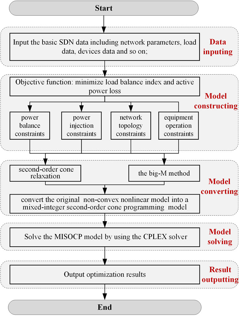
Figure 2. Flowchart of the SDN dynamic reconfiguration method for load balancing.
The validity of the model and method proposed in this paper is verified with a 3-station, 6-wire snow-shaped distribution network. The structure diagram of SDN is shown in Figure 3, including 3 substations, 6 feeders, 21 ring main units, and 27 branches. Green ring main units indicate intra-station contact switches and red ring main units indicate inter-station contact switches. The rated voltage is 10 Vk, with an allowable voltage range of 0.93 p.u. to 1.07 p.u. The maximum allowable branch current is 577 A. Substation A provides power to residential loads, Substation B provides power to commercial loads, and Substation C provides power to office loads. Table 1 lists the parameters of PV and ESS. The prediction curve of typical PV and load data is shown in Figure 4. The heavily loaded feeders involve F1, F3, F5, F6, and the lightly loaded feeders involve F2, F4.
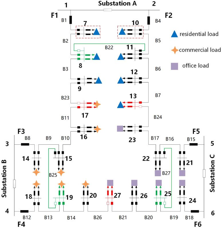
Figure 3. Schematic diagram of a 3-station, 6-wire snowflake distribution network.
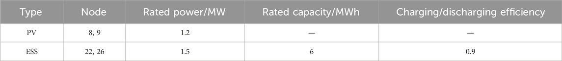
Table 1. Parameters of distributed PV and ESS.
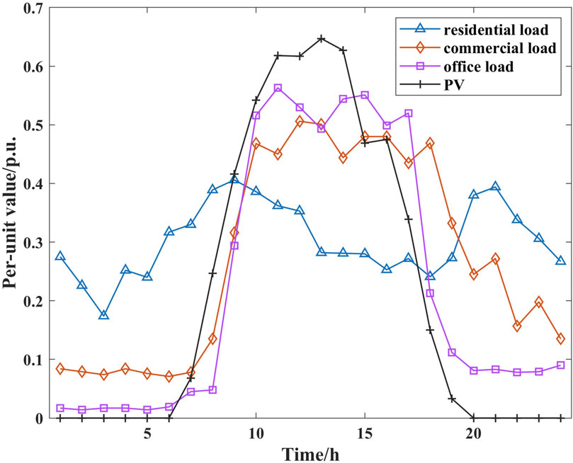
Figure 4. Prediction curve of typical PV and load data in case 1.
Different types of loads have different patterns of curve change. Residential load mainly includes the electricity consumed by residents’ electrical equipment, which experiences steady growth with economic development and notable seasonal fluctuations. Commercial load mainly includes air-conditioning, lighting, power, and other electrical loads in commercial areas. Peak electricity consumption hours are concentrated and stable throughout the day. Office load is closely related to the working hours, and the peak electricity consumption is mainly concentrated during these hours with a great difference between peak and valley.
The maximum number of switch actions per day is set to 4. By using the hierarchical hierarchy process (AHP), the load balance index and active power loss weighting coefficients ω1, and ω2 in the objective function are 0.846 and 0.154, respectively. The proposed method in this paper is implemented in using MATLAB R2020a, where the MISOCP model is modeled by YALMIP programming and solved by the CPLEX solver.
The following two scenarios are set up for the analysis and comparison. Scenario 1 is the benchmark scenario, which considers the PVs and ESS. Based on scenario 1, dynamic reconfiguration is considered in scenario 2.
The effectiveness of the dynamic reconfiguration model and method of SDN are verified as follows.
Step 2: Model constructing. Construct SDN dynamic reconfiguration model for load balancing to minimize load balance index and active power loss,
Step 3: Model converting. Convert the NLP model into a MISOCP model through the second-order cone relaxation and the big-M method;
The optimization results of load balance index and active power loss for SDN in scenarios 1 and 2 are listed in Table 2. The load balance index is 28.71 in scenario 1 and 24.48 in scenario 2, which is reduced by about 14.73%. The maximum load ratio of the feeder is reduced from 92.46% to 59.24%, which is reduced by about 33.22%. The all-day active power loss of SDN is reduced from 1,700.36 kWh to 1,552.16 kWh, a reduction of about 8.72%. With the collaborative optimization of energy storage and dynamic reconfiguration, the load balancing in SDN is greatly improved and the active power losses are reduced.
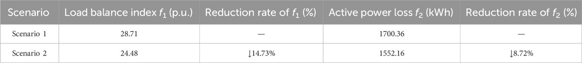
Table 2. Load balance index and active power loss optimization results.
In scenario 1, the switches on contact lines B22, B23, B24, B25, B26, and B27 are in the open state before reconfiguration. In scenario 2, the states of sectional contact switches are optimized through dynamic reconfiguration to achieve a wide range of spatial load transfer, thus enhancing overall load balance in SDN. The results of dynamic reconfiguration in scenario 2 are shown in Table 3.
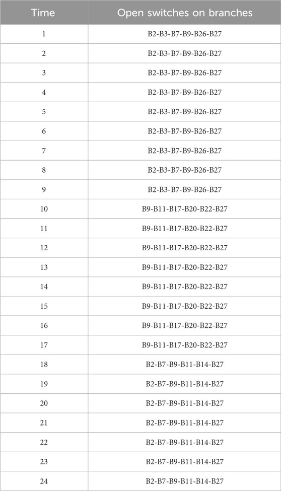
Table 3. Results of dynamic reconfiguration in scenario 2 (case 1).
At 0:00–9:00, the switches on branches B2, B3, B7, and B9 open, and the switches on branches B22, B23, B24, and B25 close. The loads of ring node 8 on feeder F1 are transferred to feeder F2 through intra-station contact on branch B22; The loads of ring nodes 9,15,16 and 17 are transferred to feeder F4 through inter-station contact on branch B23 and intra-station contact on branch B25; The loads of ring node 13 on feeder F2 are transferred to feeder F5 through inter-station contact on branch B24; At 10:00–17:00, B11, the switches on branches B11, B17, B20 and B22 open, switches on branches B2, B3, B7, and B26 close. The loads of ring node 23 on feeder F5 are transferred to feeder F2 through inter-station contact on branch B24; The loads of ring nodes 26 and 27 on feeder F6 are transferred to feeder F4 through inter-station contact on branch B26; At 18:00–24:00, the switches on branches B2, B7, and B14 open, switches on branches B17, B20, and B22 close. The different network structure topology of different periods is shown in Figure 5. Different colored parts indicate the power supply ranges of different substations.

Figure 5. The network structure topology of different periods. (A) 1:00–9:00. (B) 10:00–17:00. (C) 18:00–24:00.
The load ratio of each feeder in the snow-shaped distribution network in scenarios 1 and 2 is shown in Figure 6. In scenario 1, feeder 5 and feeder 6 are equipped with ESS. ESS absorbs electricity at the time of low power consumption, and releases electricity at the time of peak power consumption to smooth the load curve, reduce the curve volatility, and alleviate the peak load on feeder F5 and feeder F6. However, the regulation capability is limited, and the load ratios of feeders F3, F5, and F6 remain high during the time period of 8:00–18:00, up to 92.46%, and the heavy load situation is serious. In scenario 2, based on dynamic reconfiguration, the load on the feeder with high load rate is transferred to other feeder with low load rate through multiple switch contacts in the snow-shaped network feeder cluster, and the maximum load rate is reduced to 59.24%, realizing a more balanced feeder load of the whole network.
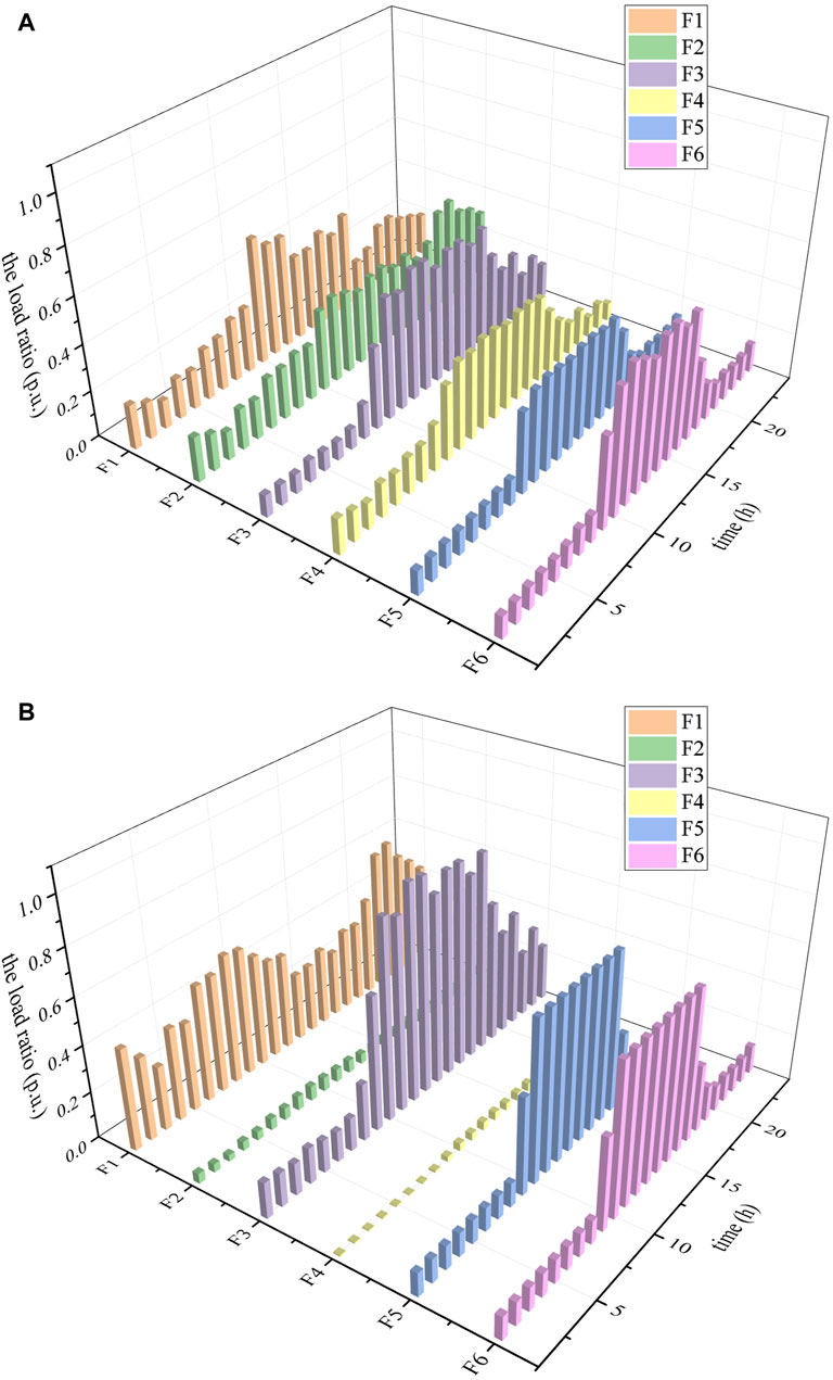
Figure 6. The load ratio of each feeder in the snow-shaped distribution network in scenarios 1 and 2. (A) scenario 1. (B) Scenario 2.
In scenario 1 and 2, the ESS output power is shown in Figure 7, which both show the trend of charging and then releasing. ESS charges during the load valley time (01:00–08:00) and then discharges the stored energy during the peak load period (10:00–17:00). The energy is transferred across time, achieving peak shaving and valley filling effects on the load curve and thereby smoothing it. During the peak load period (10:00–17:00), the active power output of ESS in scenario 1 and 2 are different. In scenario 1, the optimal dispatching of ESS can only smooth the load curve on feeder F5 and feeder F6 in substation C because of node 22 in feeder 5 and node 26 in feeder 6 equipped with ESS. In scenario 2, node 26 is in feeder 4 at 10:00–17:00 through dynamic reconfiguration. During the load valley time (01:00–08:00), the optimal dispatching of ESS can smooth the load curve on feeder F5 and feeder F6 in substation C. During the load valley time (10:00–17:00), the optimal dispatching of ESS can smooth the load curve on feeder F4 in substation B and feeder F5 in substation C through dynamic reconfiguration. The collaborative optimization of energy storage and dynamic reconfiguration achieves the “feeder-transformer-substation” three levels of load balancing.
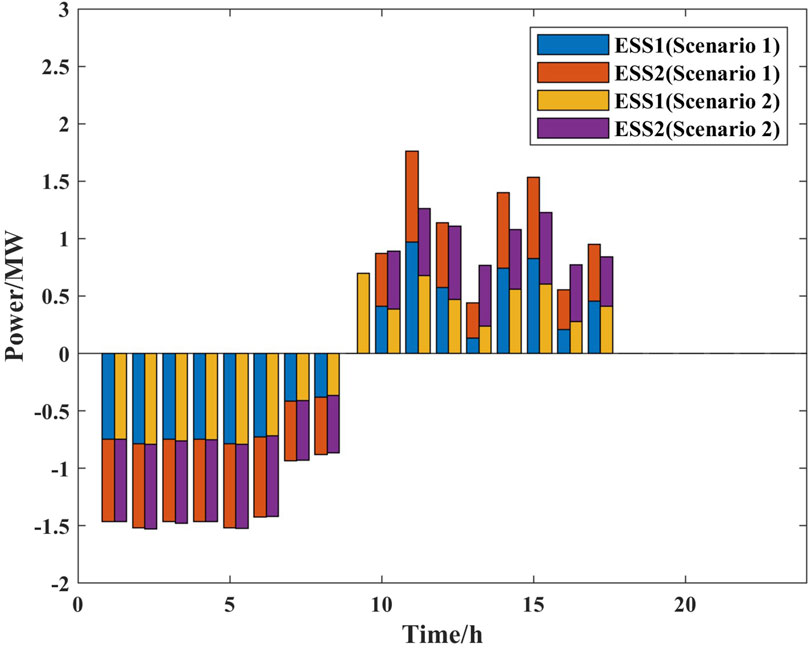
Figure 7. Energy storage output power.
The active power losses for each hourly period before and after the dynamic reconfiguration of SDN are shown in Figure 8. The voltage fluctuations at typical nodes before and after the dynamic reconfiguration are shown in Figure 9.
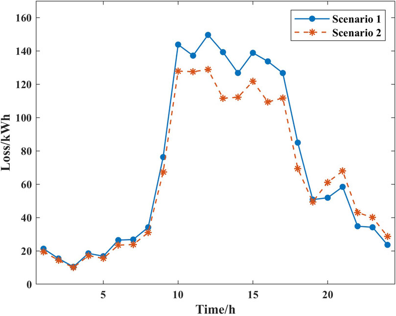
Figure 8. Active power losses in each time period.
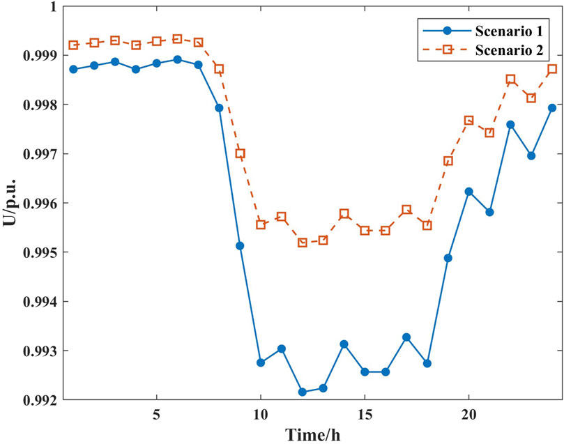
Figure 9. Node voltages in scenarios 1 and 2.
From Figures 8, 9, it can be seen that network dynamic reconfiguration in SDN effectively reduces the system active power loss, enhances the voltage level and improves the power quality. The active power loss decreases from 1700.36 kWh to 1552.16 kWh throughout the day, a reduction of about 8.72%. For instance, considering ring node 14, the node voltage increases after dynamic reconfiguration, alleviating voltage offset and enhancing the system’s voltage safety margin.
The proposed method is tested on a standard test style such as IEEE 33-node. This test system is a 12.66 kV distribution network which is shown in Figure 10. The profile of typical PV and load data is shown in Figure 11. Similar to Section 5.1, this section sets up two scenarios for comparison. Scenario 1 is the benchmark scenario, which considers the PVs and ESS. Based on scenario 1, dynamic reconfiguration is considered in scenario 2. The values of ω1 and ω2 in case 2 are the same as in case 1.
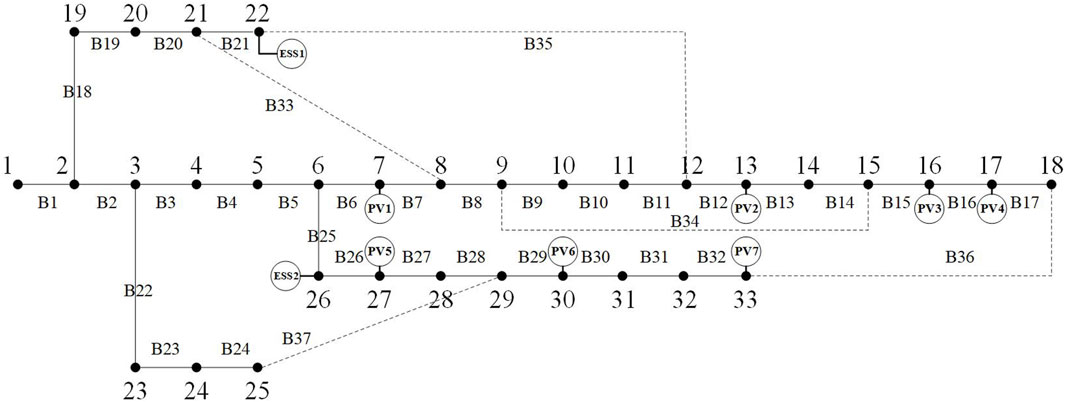
Figure 10. IEEE 33-node.

Figure 11. The profile of typical PV and load data in case2.
Table 4 lists the optimization results of load balance index and active power loss in scenarios 1 and 2. The overall load balance index is 4.4324 in scenario 1 and 2.4266 in scenario 2, which is reduced by about 45.25% by conducting the feeder load balancing method based on dynamic reconfiguration. The all-day active power loss of SDN is reduced from 1256.51 kWh to 1744.55 kWh, a reduction of about 27.98%, which is a considerable improvement of economic efficiency.
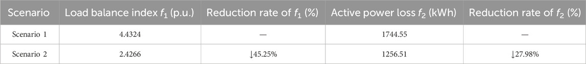
Table 4. Load balance index and active power loss optimization results.
The results of dynamic reconfiguration in scenario 2 are shown in Table 5.
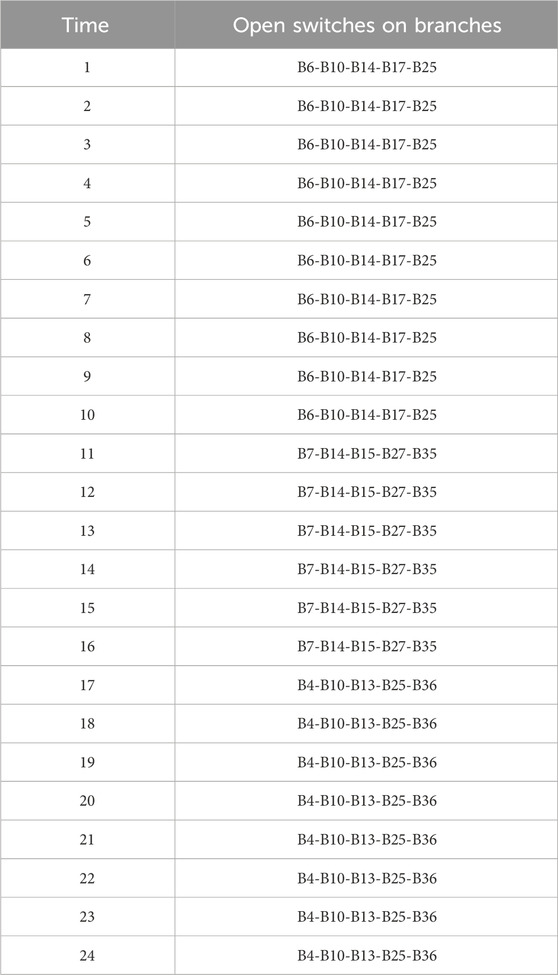
Table 5. Results of dynamic reconfiguration in scenario 2 (case 2).
Figure 12 shows the maximum power flow loading of each branch over a day for scenarios 1 and 2. The maximum power flow loading is reduced in scenario 1 by conducting dynamic reconfiguration. The unbalanced condition of the feeder load is exacerbated due to the high penetration of distributed renewable energy in scenario 1, as shown in Figure 13. The proposed dynamic reconfiguration-based feeder load balancing method, which is implemented in scenario 2, maintains the power flow loading within the desired level and significantly mitigates the feeder load unbalanced condition caused by the increasing distributed renewable energy.
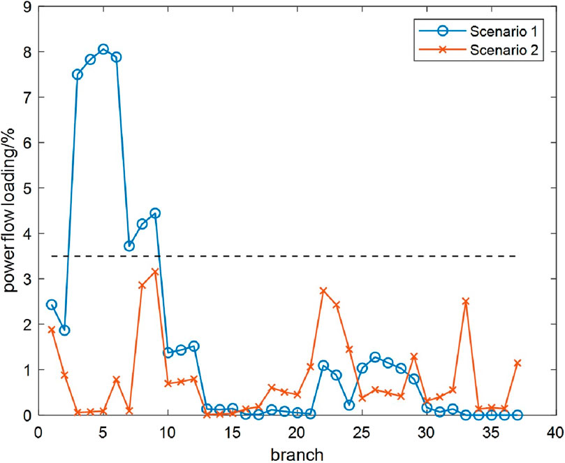
Figure 12. Maximum power flow loading of each branch in scenarios 1 and 2.
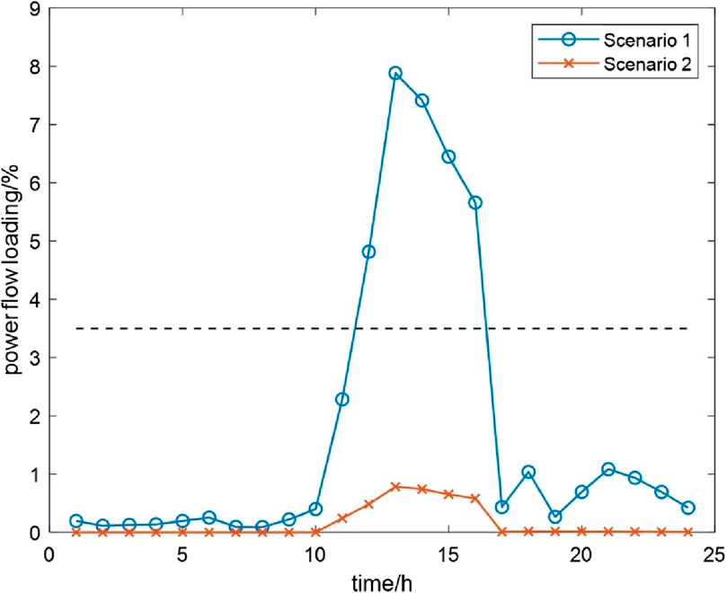
Figure 13. Power flow loading of branch B6 in scenarios 1 and 2.
Based on the characteristics of SDN frame structure, this paper establishes a multi-objective dynamic reconfiguration model for load balancing through collaborative optimal dispatching of dynamic reconfiguration and distributed energy storage system in SDN. And the second-order cone relaxation and big-M method are employed to convert the original NLP model into a MISOCP model which can be tractably solved. Case studies in an urban 10 kV distribution network and IEEE 33-node system are performed to show the effectiveness of the proposed model, the following conclusions can be drawn:
(1) The optimization results show that the safety and economy of SDN operation are both included in our formulated model to mitigate the feeder load unbalance, reduce the active power loss and improve voltage profile.
(2) Through adjusting the switching state combinations of tie switches and segment switches at the spatial level as well as by optimizing the charging and discharging states of the energy storage at the temporal level, the model proposed in this paper maximizes the advantages of inter connection and intra connection among feeder clusters in SDN, achieving the large-scale space-time load transfer, and fully excavating the power supply capacity of the distribution network.
This paper focuses on the dynamic reconfiguration strategy in SDN for feeder load balancing, flexibly transferring load through intra-station and inter-station contacts in all directions to improve system security and economic efficiency. Further research will consider additional elements such as flexible loads and electric vehicles to fully exploit the operational potential of SDN.
The original contributions presented in the study are included in the article/supplementary material, further inquiries can be directed to the corresponding author.
FL: Conceptualization, Supervision, Writing–review and editing. XW: Data curation, Methodology, Software, Writing–original draft, Writing–review and editing. ZW: Writing–review and editing. JD: Writing–review and editing.
The authors declare financial support was received for the research, authorship, and/or publication of this article. This work is supported by National Natural Science Foundation of China under Grant 51977140, the Natural Science Foundation of Tianjin under Grant 22JCZDJC00710, and Science and Technology Projects of State Grid Tianjin Electric Power Company under Grant SGTJCN00FZJS2300841.
Thanks for the data support provided by the project team members from State Grid Tianjin Electric Power Company. The authors would also like to thank the reviewers for their valuable comments and suggestions to improve the quality of the paper.
Authors ZW and JD were employed by State Grid Tianjin Electric Power Company.
The remaining authors declare that the research was conducted in the absence of any commercial or financial relationships that could be construed as a potential conflict of interest.
The authors declare that this study received funding from State Grid Tianjin Electric Power Company. The funder had the following involvement in the study: data support, study design, collection and analysis.
All claims expressed in this article are solely those of the authors and do not necessarily represent those of their affiliated organizations, or those of the publisher, the editors and the reviewers. Any product that may be evaluated in this article, or claim that may be made by its manufacturer, is not guaranteed or endorsed by the publisher.
Aldik, A., and Venkatesh, B. (2020). Reactive power planning using convex line-wise power balance equations for radial distribution systems. IET Generation, Transm. Distribution. 14, 2399–2406. doi:10.1049/iet-gtd.2019.1841
Baran, M., and Wu, F. (1989a). Network reconfiguration in distribution systems for loss reduction and load balancing. IEEE Trans. Power Deliv. 4, 1401–1407. doi:10.1109/61.25627
Baran, M. E., and Wu, F. F. (1989b). Optimal capacitor placement on radial distribution systems. IEEE Trans. Power Deliv. 4, 725–734. doi:10.1109/61.19265
Cho, S., Shin, H., and Kim, J. (2012). Modeling of battery energy storage system at substation for load leveling and its economic evaluation. Trans. Korean Inst. Electr. Eng. 61, 950–956. doi:10.5370/KIEE.2012.61.7.950
Gao, H., Ma, W., Xiang, Y., Tang, Z., Xu, X., Pan, H., et al. (2022). Multi-objective dynamic reconfiguration for urban distribution network considering multi-level switching modes. J. Mod. Power Syst. Clean Energy 10, 1241–1255. doi:10.35833/MPCE.2020.000870
Hosseina, M., and Bathaee, T. (2016). Optimal scheduling for distribution network with redox flow battery storage. Energy Convers. Manag. 121, 145–151. doi:10.1016/j.enconman.2016.05.001
Jabr, R. A., Singh, R., and Pal, B. C. (2012). Minimum loss network reconfiguration using mixed-integer convex programming. IEEE Trans. Power Syst. 27, 1106–1115. doi:10.1109/TPWRS.2011.2180406
Jakus, D., Cadenovic, R., Bogdanovic, M., Sarajcev, P., and Vasilj, J. (2017). Optimal reconfiguration of distribution networks using hybrid heuristic-genetic algorithm. Energies 13, 1544–2190. doi:10.3390/en13071544
Jakus, D., Cadenovic, R., Vasilj, J., and Sarajcev, P. (2020). Optimal reconfiguration of distribution networks using hybrid heuristic-genetic algorithm. Energies 13, 1544–1611. doi:10.3390/en13071544
Ji, J. (1997). The refined strategy for substation main transformer and feeder load balancing. Int. J. Electr. Power and Energy Syst. 19, 87–91. doi:10.1016/S0142-0615(96)00023-3
Li, W., Liang, R., Luo, F., Feng, S., Yang, B., Liu, Z., et al. (2022). Response potential assessment of user-side flexible resources of regional power distribution networks based on sequential simulation of optimal operation. Front. Energy Res. 10, 01–16. doi:10.3389/fenrg.2022.1096046
López, J., Lavorato, M., Franco, J., and Rider, M. (2016). Robust optimisation applied to the reconfiguration of distribution systems with reliability constraints. IET Generation, Transm. Distribution 10, 917–927. doi:10.1049/iet-gtd.2015.0558
Lotfi, H. (2022). Multi-objective network reconfiguration and allocation of capacitor units in radial distribution system using an enhanced artificial bee colony optimization. Electr. Power Components Syst. 49, 1130–1142. doi:10.1080/15325008.2022.2049661
Lotfi, H., and Ghazi, R. (2021). Optimal participation of demand response aggregators in reconfigurable distribution system considering photovoltaic and storage units. J. Ambient Intell. Humaniz. Comput. 12, 2233–2255. doi:10.1007/s12652-020-02322-2
Lotfi, H., Ghazi, R., and Naghibi-Sistani, M. B. (2020). Multi-objective dynamic distribution feeder reconfiguration along with capacitor allocation using a new hybrid evolutionary algorithm. Energy Syst. 11, 779–809. doi:10.1007/s12667-019-00333-3
Montoya, O. D., Gil-González, W., and Molina-Cabrera, A. (2023). Practical solution for the reconfiguration problem in electrical distribution networks: a constructive heuristic approach. Rev. UIS Ing. 22, 87–98. doi:10.18273/revuin.v22n3-2023007
Silveira, C. L. B., Tabares, A., Faria, L. T., and Franco, J. F. (2021). Mathematical optimization versus Metaheuristic techniques: a performance comparison for reconfiguration of distribution systems. Electr. Power Syst. Res. 196, 107272. doi:10.1016/j.epsr.2021.107272
Tian, Z., Wu, W., Zhang, B., and Bose, A. (2016). Mixed-integer second-order cone programing model for VAR optimisation and network reconfiguration in active distribution networks. IET Generation, Transm. Distribution 10, 1938–1946. doi:10.1049/iet-gtd.2015.1228
Wang, C. (2012). Distribution network reconfiguration based on chemical reaction optimization. Power Syst. Technol. 36, 209–214. (in Chinese). doi:10.13335/j.1000-3673.pst.2012.05.017
Wang, Z., Duan, J., He, P., Wang, W., Xu, J., and Zhang, Z. (2023). Exploration on snow-shaped grid structure of urban medium voltage distribution network. Proc. CSU-EPSA. in press. doi:10.19635/j.cnki.csu-epsa.001399
Yao, G., Zhong, L. J., and Zhang, D. H. (2014). Research and practice of mesh-networking optimization for power supply by complex urban distribution network. Power Syst. Technol. 38, 1297–1301. (in Chinese). doi:10.13335/j.1000-3673.pst.2014.05.026
Yu, Y., Yang, M., Zhang, Y., Ye, P., Ji, X., and Li, J. (2023). Fast reconfiguration method of low-carbon distribution network based on convolutional neural network. Front. Energy Res. 11, 01–18. doi:10.3389/fenrg.2023.1102949
Zhang, P., and Wang, S. (2004). A new sensitivity method for static stability preventive control. Automation Electr. Power Syst. 21, 22–26. (in Chinese).
Keywords: the snow-shaped distribution network (SDN), dynamic reconfiguration, load balance, energy storage system (ESS), mixed-integer second-order cone programming (MISOCP)
Citation: Luo F, Wu X, Wang Z and Duan J (2024) A dynamic reconfiguration model and method for load balancing in the snow-shaped distribution network. Front. Energy Res. 12:1361559. doi: 10.3389/fenrg.2024.1361559
Received: 26 December 2023; Accepted: 06 June 2024;
Published: 26 June 2024.
Edited by:
Shengyuan Liu, State Grid Zhejiang Electric Power Co., Ltd., ChinaReviewed by:
Hossein Lotfi, Hakim Sabzevari University, IranCopyright © 2024 Luo, Wu, Wang and Duan. This is an open-access article distributed under the terms of the Creative Commons Attribution License (CC BY). The use, distribution or reproduction in other forums is permitted, provided the original author(s) and the copyright owner(s) are credited and that the original publication in this journal is cited, in accordance with accepted academic practice. No use, distribution or reproduction is permitted which does not comply with these terms.
*Correspondence: Fengzhang Luo, bHVvZmVuZ3poYW5nQHRqdS5lZHUuY24=
Disclaimer: All claims expressed in this article are solely those of the authors and do not necessarily represent those of their affiliated organizations, or those of the publisher, the editors and the reviewers. Any product that may be evaluated in this article or claim that may be made by its manufacturer is not guaranteed or endorsed by the publisher.
Research integrity at Frontiers
Learn more about the work of our research integrity team to safeguard the quality of each article we publish.