 Yu Zhang
 Ke Xu
Ke Xu Hui Zhang
 Shujun Lai1,2,3,4
- 1Research Institute of Exploration and Development, Tarim Oilfield Company, Korla, China
- 2R&D Center for Ultra Deep Complex Reservoir Exploration and Development, China National Petroleum Corporation (CNPC), Korla, China
- 3Engineering Research Center for Ultra-Deep Complex Reservoir Exploration and Development, Korla, China
- 4Xinjiang Key Laboratory of Ultra-Deep Oil and Gas, Korla, Xinjiang, China
This study carried out a research on the distribution characteristics of the geostress field of ultra-deep strike-slip faults, aiming to improve the exploration efficiency and development benefits of ultra-deep fault-controlled reservoirs. This study combines multiple geological information, drilling information, seismic data, and seismic attribute analysis. Taking the FI12 fault zone in the Fengman Oilfield as an example, it carried out numerical simulation of the geostress field, clarified the distribution pattern of geostress, analyzed the effectiveness of fracture mechanics, and proposed a reservoir quality evaluation method and production increase strategy based on geostress analysis. The study includes the following three aspects: 1) research on the heterogeneity of fault-controlled fractured carbonate reservoirs: Due to the existence of faults, fractures, and pores, carbonate reservoirs exhibit strong heterogeneity. These discontinuous structures lead to local stress field decreases to varying degrees. By analyzing the changes in geostress, it is possible to infer the development of faults, fractures, and pores. This provides important basis for predicting and evaluating reservoirs. 2) research on the distribution pattern of geostress: The geostress of fractured bodies exhibits a “shell-type” distribution pattern. Inside the fractured body, the geostress values are lower, indicating that this part is a favorable reservoir body. On the outside of the fractured body, the geostress exhibits high-value concentration, and this part has relatively poor permeability and can be regarded as an unfavorable drilling target. 3) research on the relationship between fault-fracture mechanical activity and reservoir quality and production capacity: Geostress and its influence on fault-fracture mechanical activity are directly related to the quality and production capacity of fault-controlled fractured carbonate reservoirs. When deploying well locations and optimizing well trajectories, geostress factors should be fully considered, and reservoir reformation efficiency should be taken into account to promote single well production increases and reservoir economic devel.
1 Introduction
Strike-slip faults are an important research area in structural geology. According to traditional views, large strike-slip faults are mainly developed on the margins of active continental plates, with long-distance extension and large slip distance. For example, the San Andreas Fault in the United States (Fossen, 2010) and the Altun Fault in China (Cui et al., 2002) are both typical examples.
However, with the improvement of seismic data acquisition technology, it has been discovered that there are also large strike slip faults within stable land blocks. Although these faults extend longer, their slip distance is relatively small, usually only a few hundred meters, and the maximum is only a few thousand meters. These faults are called intra cratonic strike slip faults and are mainly developed in tectonic stable areas, such as Siberia Basin (Gogonenkov and Timurziev, 2012), Sichuan Basin (Ma et al., 2018) and Tarim Basin (Wu et al., 2012; Yang et al., 2016; Han et al., 2017; Li et al., 2017; Lyu et al., 2017; Zheng et al., 2018; Wu et al., 2021).
Strike-slip faults within cratons play an important controlling role in the development of reservoirs and the formation of oil and gas reservoirs. In oil and gas exploration practice, these faults are often regarded as important exploration targets. Therefore, conducting research on strike-slip faults within cratons not only helps to deepen the understanding of the internal structural deformation and formation mechanisms of cratons, but also provides new ideas and directions for oil and gas exploration.
The study of strike-slip faults within cratons has important theoretical significance and production guidance value. By deeply studying the genetic mechanism, distribution pattern, and impact on reservoirs of strike-slip faults within cratons, more scientific and effective guidance can be provided for oil and gas exploration, promoting the development and utilization of oil and gas resources.
Research has shown that the control of strike-slip faults on the productivity of oil and gas wells is mainly reflected in the following aspects (Wang et al., 2018; Wang Y. et al., 2019; Li et al., 2021; Song X. et al., 2023; Wang Q. et al., 2023).
1. Formation of traps: Strike-slip faults can form various traps during tectonic movement, such as fault traps, fracture traps, and structural ridge traps. These traps can serve as spatial gather together spaces for oil and gas, affecting the productivity of oil and gas wells;
2. Control of the distribution of oil and gas reservoirs: Strike-slip faults can affect the migration and aggregation of oil and gas, making the oil and gas reservoirs exhibit directional distribution characteristics. This helps to predict the distribution of oil and gas reservoirs, guiding oil and gas exploration and development;
3. Regulation of the pressure system of oil and gas wells: Strike-slip faults can affect the pressure system of oil and gas wells, causing changes in wellbore pressure. When oil and gas wells are located near strike-slip faults, the wellbore pressure may be affected, thereby affecting the productivity of oil and gas wells;
4. Impact on the hydraulic characteristics of oil and gas wells: Strike-slip faults can alter the hydraulic characteristics of oil and gas wells, such as influencing the direction and velocity of groundwater flow. This may affect the extraction efficiency of oil and gas, further affecting the productivity of oil and gas wells;
5. Formation of preferential seepage channels: Strike-slip faults can form preferential seepage channels, enhancing the productivity of oil and gas wells. During the production process of oil and gas wells, fractures at strike-slip faults can serve as preferential seepage channels for oil and gas, making it easier for oil and gas to flow towards the wellbore, thereby increasing the productivity of oil and gas wells. Therefore, the control of strike-slip faults on the productivity of oil and gas wells is mainly reflected in the formation of traps, the distribution of oil and gas reservoirs, changes in wellbore pressure, regulation of hydraulic characteristics, and the formation of preferential seepage channels. In the process of oil and gas exploration and development, the impact of strike-slip faults needs to be fully considered to improve the productivity and extraction efficiency of oil and gas wells.
The FI12 fault zone is located in the eastern part of the Fuyuan II area (Jiao, 2017; Wang et al., 2021; Wang Qinghua et al., 2023). The overall structure of the roof of an Ordovician room in the area is gentle, and multiple sets of faults with different orientations are developed on the plane; The Paleozoic faults in the Fuyuan block are well-developed, and the fault system can be divided into two groups on the plane: northeast and northwest, both of which are strike slip faults. The activity periods can be divided into three periods. The first period is a northeast strike slip fault formed during the Middle Caledonian period, forming the fault pattern of this area. The plane is mainly characterized by linear and feathery structures, and the strike slip faults mostly have local compression and torsion properties, with a small fault distance of generally 10–20 m, Disconnect the layer from the basement to the bottom of the Ordovician Santam Formation; The second stage is the Late Caledonian period, based on the Middle Caledonian fault, the northeast trending fault in the middle of the block is further activated, and the fault layer extends from the basement to the Ordovician Santam Formation; The third stage is a northeast trending strike slip fault, only distributed in the northwest of the block. The fault style is mainly flower shaped, and on the plane, it only shows linear structures. The fault distance is relatively large, generally 10–40 m, and the fault layer is from the basement to the Permian. It can be seen that the FI12 fault zone is a “typical” fault zone of the ultra deep strike slip fault in the Tarim Basin, which is of great significance for the study of numerical simulation of the geostress field of the ultra deep strike slip fault. Moreover, the water injection flow law of the wells arranged in the fault zone is not clear from the water injection development stage, which affects the water injection development effect of the wells arranged in the fault zone (Song Xingguo et al., 2023).
Therefore, in order to improve the exploration efficiency and development benefits of carbonate reservoirs under the control of ultra-deep strike-slip faults, this article takes the FI12 fault zone in the Fuman Oilfield as an example to carry out numerical simulation of the in-situ stress field, clarify the distribution law of carbonate reservoirs under the control of strike-slip faults, clarify the correlation between factors related to in-situ stress and the quality of ultra-deep carbonate reservoirs, and provide suggestions and countermeasures based on the numerical simulation results of ultra-deep strike-slip faults, thus supporting efficient exploration and benefit development of ultra-deep carbonate reservoirs in Tarim Oilfield.
2 Geological setting
The Tarim Basin, a vast land of 560,000 square kilometers, is the largest inland basin in China and also a mysterious place with the least exploration. It is surrounded by the towering Tianshan Mountains, with majestic mountains to the north and the continuous Kunlun Mountains to the south. In the southeast of this basin, the Altyn Mountains stand tall and towering, as if they are a natural barrier to protect this land.Although its exploration level is relatively low, the abundant oil and natural gas resources here provide a solid support for China’s energy development.
The Tarim Basin is rich in geological structure and geomorphic features. According to basement structure, primary basement fault and sediment distribution, the Tarim Basin is divided into more than 10 structural units, including 6 depressions and 4 uplifts. The distribution of these structural units, from north to south, is sequentially Kuche Depression, Tabei Uplift, Awati Depression, Manjia’er Depression, Tazhong Uplift, Bachu Uplift, Tadong Uplift, Tanggu Depression, Southwest Depression, and Southeast Depression. Among them, the Shuntuo low uplift is a relatively special structural unit. Compared with the northern and central uplift of the tower, the terrain of Shuntuo low uplift presents a moderately uplifted state. The Tabei Uplift and the Tazhong Uplift are located in their northern and southern parts, respectively, forming a relatively complete structural system (Figure 1).
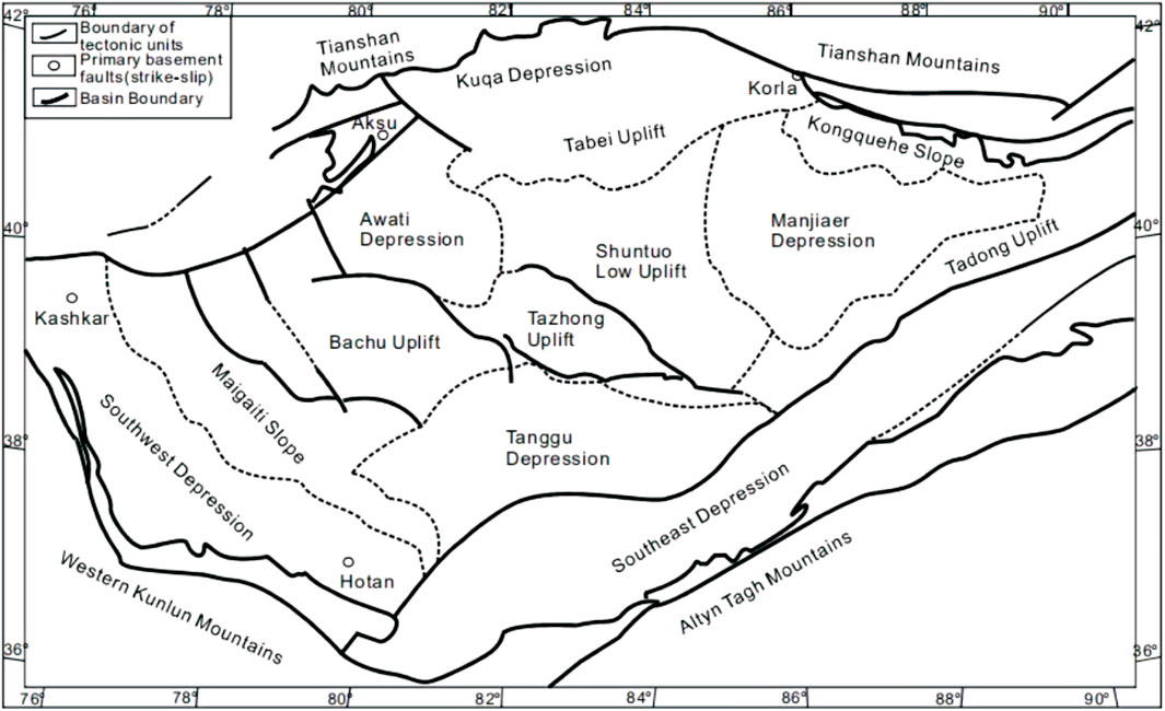
FIGURE 1. Main structural units of Tarim Basin (Mao et al., 2017).
The distribution of intracratonic strike-slip faults in the Tabei uplift, Shuntuo low uplift, and northern slope of the Tazhong uplift is an important area of geological research and is also the focus area of this study (Figure 2).
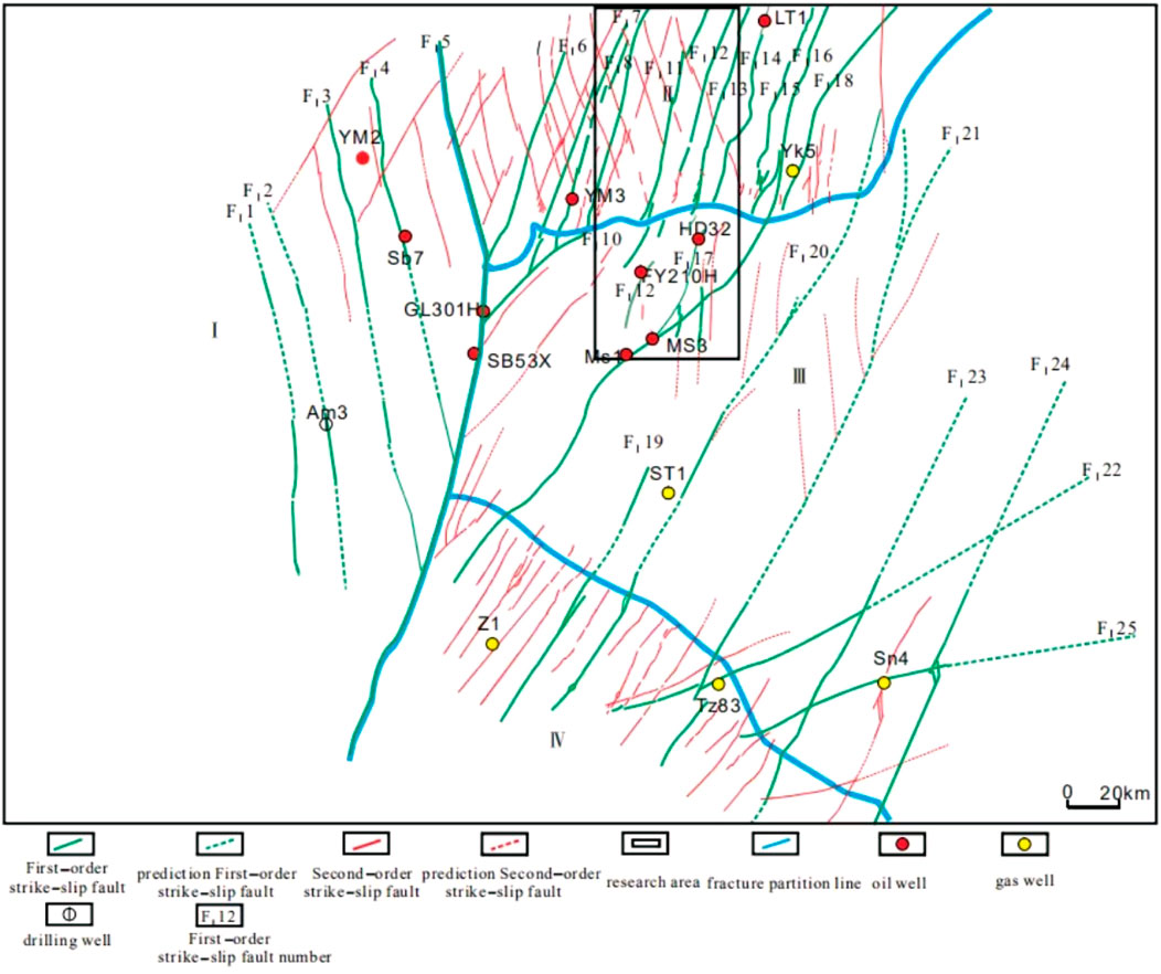
FIGURE 2. Distribution of strike slip faults in the central craton of Tarim Basin (Mao et al., 2017) (red).
The Tarim Basin has experienced a complex multistage tectonic evolution, and the northern margin of the basin and the adjacent southern Tianshan orogenic belt have experienced multistage and complex basin range coupling and basin range conversion processes, forming a variety of types of basin range coupling and conversion modes (Mao et al., 2017).
About 750 million years ago, the Rodinian supercontinent began to disintegrate, forming some new continents and oceans. In this process, the basement of the Tarim Basin separated from the surrounding land, and gradually formed the shape of the basin we see today.
In the Early Paleozoic, the Tabei Block was under the background of extension, which led to the formation of the South Tianshan Ocean. During this period, due to the extension of the crust, the southern Tianshan region began to undergo rifting and formed a marine environment. The existence of this ocean had an important impact on the evolution of life at that time and laid the foundation for later tectonic evolution. The southern part of the Tarim Block developed a tectonic system called the Paleotethys Trench-Arc-Basin System. This tectonic system was formed during the closure of the Paleotethys Ocean and consists of tectonic units such as trenches, arcs, and basins (Li et al., 2020).
Manjiaer Depression is an important tectonic unit in the Tarim Basin, and its formation and evolution are closely related to the surrounding geological environment and geodynamic process. In the Early Paleozoic, with the extension of the crust, the eastern part of the Tarim block began to appear rift, forming the embryonic form of Manjiar Depression.
Over time, the Manjiaer Depression has undergone multiple periods of tectonic movement and sedimentation. Under the influence of tectonic movement, the boundaries of the Manjiaer Depression have gradually expanded, and the internal structure has become more complex. At the same time, a large amount of sediment has accumulated within the depression, forming thick sedimentary layers (Figure 1).
The extensional environment underwent changes during the Middle Ordovician, and subduction began, leading to the closure of the Kudi Ocean in the southwest. Kudiyang is an ancient sea area in the Tarim Basin, which existed in the early Paleozoic era. In the Middle Ordovician, with the movement of the Earth’s tectonic plates and the strengthening of their interactions, the two sides of the Kudi Ocean began to compress, forming reverse thrust structures and related high-pressure metamorphic rocks. This process marked the gradual closure of the Kudi Ocean, which had an important impact on the tectonic evolution of the Tarim Basin. On the one hand, the closure of the Kudi Ocean has led to adjustments and changes in the stress field within the basin, further affecting the tectonic movement and crustal deformation in the surrounding areas. On the other hand, the closure of the Kudi Ocean has also led to changes in sedimentation, affecting the distribution and characteristics of sedimentary rocks in the basin. At the same time, the closure of Kudiyang also provided conditions for the formation of oil and gas resources. During the closure of the Kudi Ocean, a large amount of organic matter is enriched in seabed sediments, providing a material basis for the generation of oil and gas. With the movement and tectonic evolution of the crust, these organic substances are transformed into oil and gas under appropriate conditions, forming the oil and gas reservoirs in the current Tarim Basin.
The tectonic environment of the Tarim Basin has undergone an evolutionary process from extension to compression.
The evolution of this tectonic environment has had an important impact on the geological characteristics and resource distribution of the Tarim Basin. In an extensional environment, a large amount of sediment and organic matter were formed in the basin, which were buried and preserved in the subsequent compression environment, forming important oil and gas resources. During the interaction and movement of the Earth’s tectonic plates, the newly formed marginal orogenic belt in the southwest gradually formed and developed. The formation of this type of orogenic belt is closely related to processes such as crustal compression, shortening, and magmatic activity. With the formation and evolution of the orogenic belt, the Tazhong Uplift and the Tabei Uplift gradually formed (Figure 1).
On the one hand, the newly formed active margin orogenic belt exerts a compressive force on the Tazhong uplift and the Tabei uplift. This compressive force causes the crust to deform and rise, forming structural features of uplift. At the same time, magmatic activity within the orogenic belt also provides a material basis for the formation of uplift. The upward migration and crystallization of magma into rock increases the material density of the crust, further promoting crustal uplift and uplift.
On the other hand, the newly formed active margin orogenic belt also affected the sedimentation and structural characteristics of the Tazhong uplift and the Tabei uplift. Under the influence of the orogenic belt, the depositional patterns and characteristics of sediments in the uplift areas changed, forming specific sedimentary layers and structural features.
At the end of the Late Ordovician, with the mutual collision of plates and the compression and shortening of the crust, the Kangxiwar East Kunlun Ocean and the Altun Ocean gradually closed, forming a strong orogeny. This orogeny led to the uplift and deformation of the crust in the south of the Tarim Basin, forming structural features such as thrust faults and folds. At the same time, the excavation of the crust caused the sediment to be stripped and transported, forming geomorphic features such as alluvial fans and canyons.
Thrusting has an important impact on the structural pattern and resource distribution in the southern Tarim Basin. On the one hand, the thrust action causes changes in the stress field of the crust, affecting the tectonic movement and crustal deformation in the surrounding areas. On the other hand, thrust also leads to the redistribution and metamorphism of sediments, affecting the distribution and characteristics of sedimentary rocks.
From the compressive stress field environment in the south to the formation and collision of the island arc in the middle Tianshan Mountains, to the opening and magmatic activity of the ancient Tethys Ocean, and the collision between the Eurasian plate and the Tarim block, a series of geological events together shape the present Tarim Basin (Wang Q. et al., 2019).
3 Numerical simulation method of in-situ stress field
The numerical simulation of the stress field of ultra-deep strike-slip faults is summarized in the following 10 steps (Figure 3).
1. Interpretation of faults in earthquake: First, collect relevant seismic data and perform necessary preprocessing on the raw data. Through analyzing the seismic data, identify and locate underground faults.
2. Loading fault: Based on known seismic data and interpretation results, establish a deterministic model. Load the identified fault information into this model.
3. Using Likelihood fracture prediction technology to calculate similarity: Extracting relevant attributes, such as likelihood attributes, based on seismic data to describe the similarity between acquisition points. By setting a certain threshold or criterion, information related to fracture development can be screened from the calculated similarity.
4. Extract attributes and characterize fractures using seismic data: Select seismic data related to fracture characterization, extract attributes that can describe fracture characteristics from the selected seismic data, and characterize or depict the location and morphology of fractures in the model based on the extracted attributes and previously predicted fracture probabilities. Integrate all processing and modeling results to form a complete geological model.
5. Classify and carve different types of storage bodies (Figure 4): Before carving the pores and holes, it is necessary to integrate and utilize the existing logging interpretation and geological data. Based on the structural description of the fault-controlled reservoir, the fractal dimension algorithm is used to construct the initial model. The microscopic characteristics of the model are controlled according to the changes in seismic amplitude, and by strengthening the seismic facies control factors, the spatial heterogeneity of the fault-controlled reservoir can be more accurately highlighted. According to the differences in logging porosity thresholds for different types of reservoirs, different types of reservoirs are carved according to their classification (Li et al., 2021).
6. Utilizing structural tensor attributes to characterize the boundary of fault-controlled reservoirs: Structural tensor attributes are a method for describing the texture characteristics of seismic data. By analyzing this attribute, the boundaries of fault-controlled reservoirs can be identified. Specifically, the boundaries of fault-controlled reservoirs exhibit unique and disordered texture characteristics on structural tensor attribute profiles.
7. Determine the threshold value of the structural tensor property through the calibration of the drilling time curve: By analyzing the changes in the drilling time curve, a threshold value for the structural tensor property can be calibrated.
8. Assign rock mechanical parameters directly to the model grid: The rock mechanical parameters obtained from seismic data are directly assigned to the model grid. In order to reduce the influence of boundary effects, the modeling range usually extends outside the fault zone to ensure that the internal model is closer to the actual situation. This can make the model more realistic and reflect the actual mechanical properties of underground rocks.
9. Setting model boundary conditions: determining the direction of in-situ stress based on regional structural analysis; determining the direction of in-situ stress based on drilling-induced fractures and wellbore collapse interpretation; constructing a single-well in-situ stress profile; through comprehensive analysis of these factors, the magnitude of in-situ stress can be constrained or limited, making the calculation results more accurate and reliable.
10. Automatic calculation of stress value: After setting the boundary conditions and entering relevant parameters, numerical simulation software can be used to automatically calculate the in-situ stress values. The compressive strength exceeds 100 MPa, which is equivalent to or even exceeds the mechanical parameters of reservoir rocks in the Kelasu tectonic belt with a depth of 7,000–8,000 m. The compressive strength of the reservoir in the Qiulitag tectonic belt with a depth of 6,000 m is only about 70–80 MPa. Construction data shows that the fracture pressure gradient of the Jurassic Ah Formation in the Dibei gas reservoir is about 2.4 MPa/100 m, and the construction pressure is about 95–100 MPa.
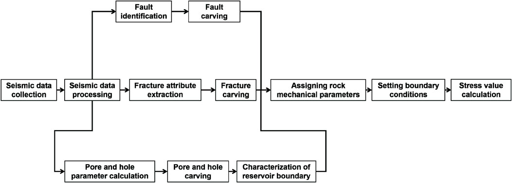
FIGURE 3. Flowchart of numerical simulation of in-situ stress field.
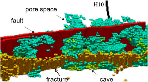
FIGURE 4. Characterization of faults, fractures, caves, and pores based on seismic data and attribute extraction analysis.
4 Calculation method and results of in-situ stress of single well
The calculation method of in-situ stress for single well is mainly divided into the following three steps.
4.1 Evaluation of the orientation of the main stress today
① Wellbore collapse method.
There are two methods to evaluate the current principal stress orientation using the drilling wellbore collapse method:
a) Using imaging data such as formation dip, resistivity, and sonic wave, a wellbore imaging map is obtained through processing. Looking for a symmetrical strip-shaped image with a certain width in the map indicates wellbore collapse. The orientation indicated in the image is the horizontal minimum principal stress orientation, and its vertical direction is the horizontal maximum principal stress orientation.
b) Extract the formation dip, well deviation in imaging data, wellbore azimuth, multi-arm caliper, No. 1 polar plate azimuth, and relative azimuth data. Use a rose diagram to statistically analyze the azimuth of the caliper expansion part. The resulting azimuth is the minimum horizontal principal stress azimuth, and its vertical direction is the maximum horizontal principal stress azimuth.
② Drilling induced fracture method.
Identifying fractures with characteristics of splay, symmetry, or straight, symmetrical features from the formation dip and acoustic and electrical imaging maps is the stress release-induced fracture in drilling. The directional angle value is read from the scale at the top of the figure, which is the maximum horizontal principal stress orientation.
③ Fast transverse wave azimuth method.
The azimuth of the fast shear wave in the formation is obtained using the dipole array acoustic logging data processing, and the azimuth with the highest frequency is obtained using a rose diagram statistics, which is the maximum horizontal principal stress azimuth (Yang et al., 2008; Wang et al., 2009).
4.2 Evaluation of three-axis stress today calculation of vertical stress
In the formula: σv-pressure of overlying strata, MPa; ρ0—average density of the formation in the depth section without logging density value, g/cm3; ρ-density of the formation, g/cm3; H0 - refers to the starting depth of density logging, m; H - refers to the depth of the calculation point, m.
② Evaluation of horizontal principal stress.
The standard prioritizes the use of small-scale fracturing and formation leakage experimental methods to determine the horizontal minimum principal stress of the formation. When there is no data from small-scale fracturing and formation leakage experiments, the following calculation formula is used to obtain the horizontal principal stress using well logging data (Wang, 1993; Xu and Shen, 2005; Li and Liu, 2006).
In the formula: σH–maximum horizontal principal stress, MPa; σh–horizontal minimum principal stress, MPa; σv—pressure of overlying strata, MPa; PP–formation pore pressure, MPa; μ–Poisson’s ratio, dimensionless; α—Biot coefficient; εh—strain in the direction of the minimum horizontal principal stress, mm; εH—strain in the direction of the maximum horizontal principal stress, mm; E − Young’s modulus, GPa.
4.3 Evaluation of rock mechanical parameters
Through analysis of well logging data, especially acoustic logging data and density logging data, rock mechanical parameters such as Young’s modulus and Poisson’s ratio can be calculated.
From the single well in-situ stress calculation results (Figures 5, 6), it can be seen that the locations where the current in-situ stress values decrease are the ones with developed fractures, holes, and pores.
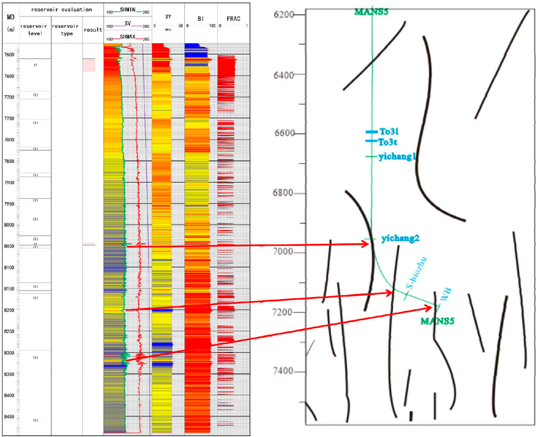
FIGURE 5. Correspondence between the in-situ stress and seismic profile interpretation of ManS 5 Well.
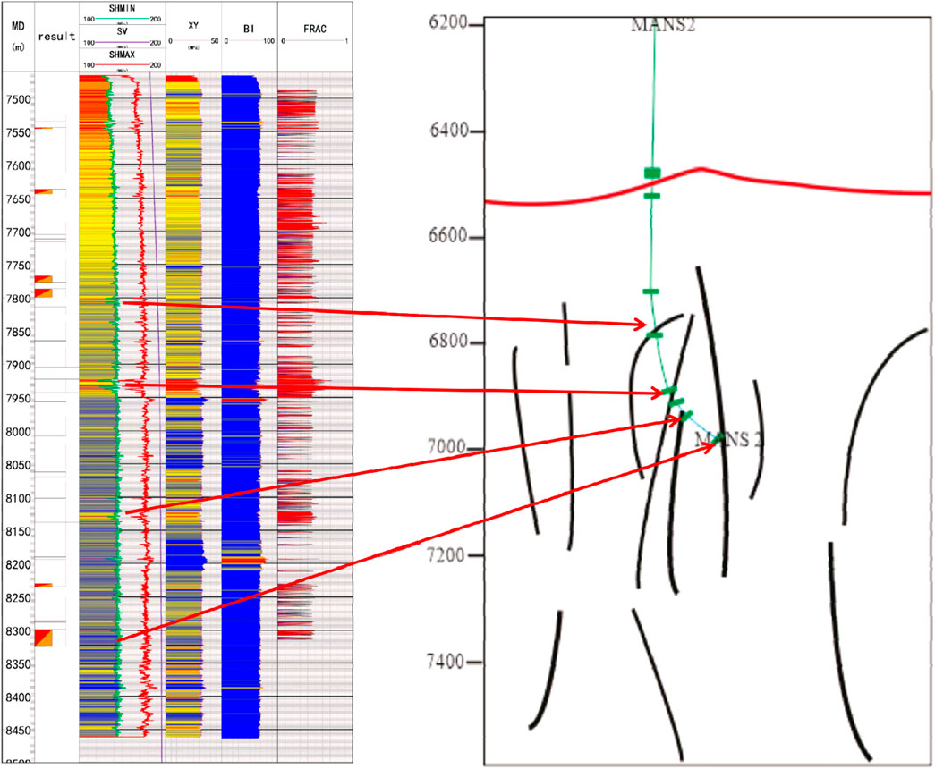
FIGURE 6. Correspondence between the in-situ stress and seismic profile interpretation of ManS 2 Well.
5 Numerical simulation results
Figure 7 shows the distribution of the minimum horizontal principal stress. Based on the information in the figure, the following observations can be made:
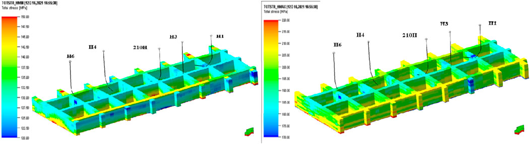
FIGURE 7. Simulation results of the maximum and minimum horizontal principal stress in the in-situ stress field of the FI12 fracture zone.
In the vertical direction (with the increase of depth):
• The ground stress gradually increases. In the horizontal direction (along the extension direction of the fault):
• There are differences in the magnitude of stress values, which are segmented. Overall characteristics:
• The in-situ stress values at fracture zones and fissures are low.
• The degree of stress reduction varies among different fracture-cave systems, indicating a strong heterogeneity.
• The heterogeneity at the bottom of the target layer slightly decreased.
• The magnitude of stress reduction in the fault zone weakens.
Summary: Figure 7 show the spatial distribution characteristics of the maximum and minimum horizontal principal stresses. This information is important for understanding the impact of faults and fractures on geostress, as well as for predicting the stability of geological structures and engineering projects.
Figure 8 combines the stress profile of a single well with seismic attribute profiles, providing insight into the variation of in-situ stress in different geological structures. Based on the information in the figure, the following conclusions can be drawn:
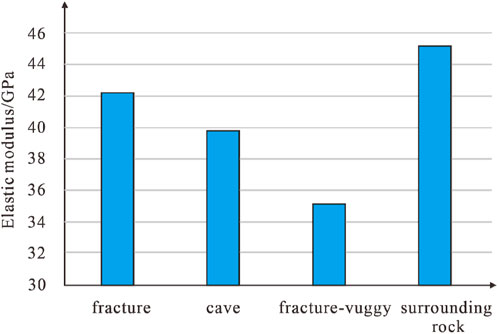
FIGURE 8. Statistical diagram of elastic modulus of different types of units in ManS 2 well.
In the fracture-cave area, the elastic modulus decreases the most, reaching 22.25%. This indicates that in the fracture-cave area, the rigidity and strength of the rock significantly decrease, which may be due to dissolution and tectonic activity.
The in-situ stress in the cave area also decreased by 11.92%, indicating that the formation of caves has an impact on the stress state of surrounding rocks.
The in-situ stress in the fracture zone decreased by 6.40%. Compared to fracture-cave bodies and karst caves, the decrease in in-situ stress in the fracture zone was relatively small, but still showed a certain degree of stress reduction.
Summary: Figure 8 shows the influence of different geological structures on stress through the combination of single-well stress profiles and seismic attribute profiles. These data are of great significance for deepening our understanding of the stress state of underground rocks and the stability of geological structures, and provide a basis for geological engineering design and risk assessment.
6 Discussions
6.1 The distribution characteristics of crustal stress in the fracture-cave system
Figure 9 displays the stress distribution changes at karstic voids. Different degrees of stress reduction are observed at the void edges, and there is also a certain range of stress elevation at the void margins. This stress distribution suggests that a high-stress “shell” region exists around the voids. To further clarify the stress “shell” distribution of voids, a three-dimensional geological model of the fracture-cave system was established (Figure 10). By varying the elastic modulus of the karstic voids, the impact of voids on the current stress distribution can be analyzed.
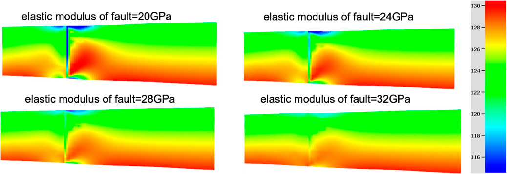
FIGURE 9. Analysis on the stress distribution characteristics of the FI12H well area.
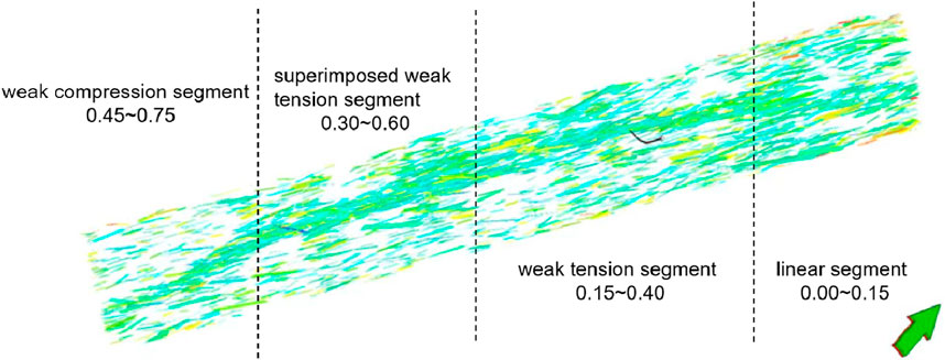
FIGURE 10. Analysis diagram of mechanical effectiveness of FI12 fault.
Based on the above information, the following conclusions can be drawn: By analyzing the impact of voids on the current stress distribution, it can be found that different voids have different ranges of influence on stress. This difference may be related to factors such as the size, shape, location, and surrounding rock properties of the voids.
Summary: The information in Figure 10 suggests that the high-stress “shell” around voids is an important factor affecting stress distribution.
Given the stress background of the known FI12 fault, we can establish the following model rock mechanical property parameters and boundary mechanical conditions:
Sv gradient = 0.0256 MPa/m.
SH gradient = 0.0234 MPa/m.
Sh gradient = 0.0187 MPa/m.
Mechanism of normal faulting.
SH direction = 59°N.
The simulation results indicate that the larger the difference in elastic modulus between the cave body and matrix, the more pronounced the decrease in in-situ stress within the void and the larger the influence range of the “shell” outside the void. This suggests that the “shell-type” stress distribution pattern of fracture-cave systems mainly depends on the difference in elastic modulus between the matrix and voids.
Therefore, to better understand and predict the stress distribution pattern, we need to further investigate the difference in elastic modulus between the matrix and voids, as well as how this difference affects stress distribution.
Based on the above analysis, we can draw the following conclusions: As the elastic modulus of voids increases, the current in-situ stress values also increase accordingly. This suggests that in underground rocks, if the elastic modulus of voids is relatively high, then the in-situ stress values will also increase accordingly. This relationship may be caused by the bearing and transmission effects of voids on in-situ stress.
Under conditions where vertical stress remains constant, the stress values are smallest for normal faulting mechanisms, largest for reverse faulting mechanisms, and intermediate for strike-slip mechanisms. This indicates that different faulting mechanisms have a significant impact on stress distribution. Normal faulting mechanisms typically result in a decrease in in-situ stress values, while reverse faulting mechanisms lead to an increase in in-situ stress values. Strike-slip mechanisms have relatively stable stress values that fall between normal and reverse faulting mechanisms.
Summary: These conclusions further confirm the important influence of voids and faulting mechanisms on stress distribution. Based on the above analysis, a further exploration of fracture-controlled stress distribution patterns and their impact on fluid flow in fracture-cave systems can be proposed. This model includes four scenarios:
a) The karstic void is completely filled with oil and gas: In this case, the stress distribution within the karstic void may be influenced by the supporting effect of oil and gas, resulting in a more uniform stress distribution and a decrease in in-situ stress values. The influence range of the high-stress “shell” outside the void may also be correspondingly reduced.
b) The karstic void is half filled with oil and gas and half filled with breccia: In this situation, the mixed filling of oil and gas with breccia may affect stress distribution. Due to the higher rigidity and strength of breccia, it may increase in-situ stress values within the void. At the same time, the combination of oil and gas with breccia may also reduce the influence range of the “shell” outside the void.
c) The oil and gas are filled within breccia pores: This situation is similar to scenario a). Oil and gas filling within breccia pores may affect stress distribution and decrease in-situ stress values. The influence range of the high-stress “shell” outside the void may also be correspondingly reduced.
d) The cave is filled with breccia cementation:In this case, the distribution of ground stress in the cave may be mainly controlled by the cementation of breccia. Due to the cementation of breccia, the rigidity and strength of the cave may be increased, thereby increasing the ground stress value. At the same time, due to the cementation of breccia, the influence range of the ground stress “shell” may also be correspondingly reduced.
Based on the above analysis, it can be concluded that as the difference between oil and gas and breccia inside the cave decreases, from a to d, the difference between inside and outside the cave decreases, and thus the degree of “shell-type” ground stress mode decreases. This indicates that the distribution pattern of ground stress is affected by the nature and distribution of the fillings inside the cave. Understanding this impact can help better predict the stability and potential risks of underground structures, and provide more accurate basis for geological engineering design and resource development.
6.2 Evaluation of fracture activity
Fracture activity is an important parameter used to characterize the sliding tendency of fracture surfaces and reflect the permeability and fluid transport effectiveness of fractures. Under the influence of regional stress fields, the stress on the fracture surface can be decomposed into an effective normal stress σne perpendicular to the fracture surface and a shear stress τ parallel to the fracture surface. The ratio of these two stresses can be used to indicate the sliding tendency of the fracture surface.
In addition, the physical properties (such as roughness) and mechanical properties of the fault zone itself can also affect its sliding tendency. Therefore, the sliding tolerance factor is an important indicator that comprehensively considers these factors.
The calculation method of fault activity is as follows:
Calculate the effective normal stress σne and shear stress τ perpendicular to the fracture surface.
Calculate the ratio of the two stresses, which is the slip tolerance factor. This ratio can be used to indicate the slip tendency of the fracture surface (Xu et al., 2023).
Considering the differences in physical and mechanical properties of the fault zone itself, the slip tolerance factor is corrected.
Based on the magnitude of the fault activity index, the sliding trend of the fault plane and the effectiveness of fluid transport are evaluated.
It should be noted that the calculation of fault activity requires consideration of multiple factors and requires comprehensive analysis and evaluation in conjunction with actual conditions.
Therefore, in practical applications, appropriate adjustments and modifications need to be made based on specific circumstances.
Based on the above analysis, the mechanical effectiveness of the FI12 fault can be segmented (Figure 10). Overall, it can be divided into four segments:
Weak compression uplift section: The fault activity coefficient is between 0.45 and 0.75.
Stacking weak pull segmentation: The fault activity coefficient is between 0.30 and 0.60.
Weak pull segmentation: The fault activity coefficient is between 0.15 and 0.40.
Linear segment: The fault activity coefficient is 0–0.15.
In addition, the productivity of oil and gas wells on this fault zone is well correlated with the effectiveness of fracture mechanics. This indicates that the fracture-fracture system plays a key role in the development of oil and gas reservoirs controlled by faults. Therefore, segmented evaluation of the mechanical effectiveness of fracture-fracture systems can provide important evidence for the prediction of oil and gas well productivity and the development strategy formulation.
6.3 Application of in-situ stress research in oil and gas production
It is very important to fully consider geomechanical factors in optimizing the deployment of carbonate rock wells with controlled breakage. In order to optimize high-quality reservoirs and take into account the efficiency of reservoir reconstruction, as well as ensure the success rate of well placement, the following are some countermeasures and considerations based on geological stress:
When drilling into a cave, it is important to observe whether the drilling tools are empty and whether the drilling fluid is leaking. If there is active oil and gas display and no significant collapse of the wellbore, the evaluation result of in-situ stress is low, indicating that a favorable reservoir has been encountered. In this case, priority should be given to maintaining the current well location and taking appropriate measures to protect and utilize this favorable reservoir.
When the wellbore encounters the periphery of the cave, if there is a small amount of leakage, low oil and gas shows (total hydrocarbon values are generally below 0.5%), and imaging logging shows a small amount of collapse of the wellbore wall, indicating a small number of natural fractures, it indicates that the drilling has encountered the periphery of the favorable reservoir and there is a certain degree of stress concentration. In this case, large-scale sand fracturing can be used to communicate the reservoir to increase its permeability.
When the wellbore encounters the periphery of the cave, if there is no leakage or venting, no good oil and gas shows, and there is a serious stress-type wellbore collapse on the wall, it indicates that a strong stress shell outside the cave has been encountered. In this case, it is recommended to review the relationship between the wellbore, cave, fractures, and ground stress, and consider taking the approach of deepening or sidetracking to continue drilling towards favorable reservoirs (cave or fracture zones). This can avoid drilling inside the strong stress shell, improve drilling efficiency, and increase the chance of finding favorable reservoirs.
In general, in-situ stress is one of the key factors affecting the success of drilling in fault-controlled carbonate reservoirs. Therefore, when deploying well locations, it is necessary to fully consider geomechanical factors to maximize the opportunity to find favorable reservoirs and reduce drilling risks.
When drilling favorable reservoirs, there will be a significant decrease in stress on the stress profile. Well 212H and Well 216H have low stress zones within a certain depth range, and these low-stress zones are consistent with oil reservoir logging interpretation. This indicates that these two wells have successfully drilled favorable reservoirs and exhibit high oil production.
According to the analysis of the 3D geomechanical model, the mechanical activity of the fractures around the 216-H4 well is medium-to-poor. In particular, the opening pressure equivalent drilling fluid density of most fractures around the wellbore is high, while the opening pressure equivalent drilling fluid density of a fracture on the east side is low. This indicates that the opening pressure of fractures around the well is high, requiring high-pressure fluid to activate and communicate with the reservoir.
To effectively communicate with the reservoir, it is recommended to inject high-pressure liquid into Well 216-H4. Through calculation, the density of the injected liquid should be 1.05 g/cm³, and the injection pressure should be approximately 30–47 MPa. After the transformation, the daily oil production of this well has significantly increased, exceeding 220 m³.
In summary, by analyzing the in-situ stress profile and reservoir characteristics, we can better understand the distribution and properties of the reservoir, and provide important guidance for well placement and reservoir modification.
7 Conclusion
(1) Due to the strong heterogeneity of the fracture-controlled vuggy reservoir, faults, fractures, and vugs can lead to varying degrees of reduction in the local stress field. Therefore, the development and internal material composition of fractures and vugs can be inferred based on the degree of stress reduction. This inference method helps to better understand the characteristics and properties of the reservoir.
(2) The crustal stress field of the fracture-cave body presents a “shell-type” distribution pattern. In this pattern, the low-value region inside is a favorable reservoir body, while the outer strong stress shell is characterized by stress concentration and poor permeability. During drilling, if strong stress shells are encountered, wellbore collapse may occur, making these areas unfavorable drilling targets. To avoid this situation, it is recommended to adopt large-scale reconstruction, deepening, or sidetracking to avoid such areas.
(3) The in-situ stress and the mechanical activity of fractures and joints under its influence have an impact on the quality and productivity of fracture-controlled, fracture-cave reservoirs. Therefore, in the optimization process of well placement, the factor of in-situ stress should be fully considered. By optimizing high-quality reservoirs and taking into account reservoir reconstruction efficiency, the success rate of well placement can be guaranteed. 1) The heterogeneity of fault-controlled vuggy reservoirs is significant. Faults, fractures, and cavities cause varying degrees of stress reduction in the local stress field. Based on this, it is possible to deduce the development and internal composition of faults, fractures, and cavities by analyzing the extent of stress reduction.
Data availability statement
The original contributions presented in the study are included in the article/Supplementary material, further inquiries can be directed to the corresponding author.
Author contributions
YZ: Writing–original draft. KX: Conceptualization, Writing–original draft. HZ: Funding acquisition, Supervision, Writing–original draft. SL: Data curation, Software, Writing–original draft. JL: Data curation, Methodology, Writing–review and editing. ZQ: Formal Analysis, Resources, Visualization, Writing–review and editing.
Funding
The author(s) declare financial support was received for the research, authorship, and/or publication of this article. This study was supported by PetroChina Tarim Oilfield Company Science and Technology Project “Oil and Gas Field Geomechanics Technology Research and Application (II)” No. T202308.
Conflict of interest
Authors YZ, KX, HZ, SL, JL, and ZQ were employed by Tarim Oilfield Company. Authors YZ, KX, HZ, SL, JL, and ZQ were employed by China National Petroleum Corporation (CNPC).
Publisher’s note
All claims expressed in this article are solely those of the authors and do not necessarily represent those of their affiliated organizations, or those of the publisher, the editors and the reviewers. Any product that may be evaluated in this article, or claim that may be made by its manufacturer, is not guaranteed or endorsed by the publisher.
References
Cui, J., Zhang, X., and Li, P. (2002). The Altun fault: its geometry, nature and mode of growth. Acta Geosci. Sin. 23 (6), 509–516.
Gogonenkov, G. N., and Timurziev, A. I. (2012). Strike-slip faulting in the west siberian platform: insights from 3D seismic imagery. Comptes Rendus Geosci. 344 (3/4), 214–226. doi:10.1016/j.crte.2011.09.010
Han, X., Deng, S., Tang, L., and Cao, Z. (2017). Geometry, kinematics and displacement characteristics of strike-slip faults in the northern slope of Tazhong uplift in Tarim Basin: a study based on 3D seismic data. Mar. Petroleum Geol. 88, 410–427. doi:10.1016/j.marpetgeo.2017.08.033
Jiao, F. (2017). The significance of hydrocarbon exploration in the NE trending strike-slip fault belt in Shuntuoguole area, Tarim Basin. Oil Gas Geol. 38 (5), 831–839. doi:10.11743/ogg20170501
Li, Y., Wang, Q., and Ma, Y., (2020). Structural geometry and evolution of an intracratonic strike-slip fault zone: a case study from the north SB5 fault zone in the Tarim Basin, China. J. Struct. Geol. 146, 1–20.
Li, Y., Wang, Q., and Ma, Y., (2021). Modeling and application of crustal stress field in fault-controlled fractured-vuggy reservoirs of the Fuman oilfield. J. Petroleum Sci. Eng. 190, 108–124.2021
Li, Z., and Liu, J. (2006). Application of one-dimensional geomechanical model in dam engineering. Water Power 32 (6), 59–62.
Li, P., Chen, H., and Tang, D., (2017). Coupling relationship between NE strike-slip faults and hypogenic karstification in middle-lower Ordovician of Shunnan area, Tarim Basin, Northwest China. Earth Sci. 42 (1), 93–104.
Lyu, H., Zhang, S., and Ma, Q. (2017). Classification and formation mechanism of fault systems in the central and northern Tarim Basin. Petroleum Geol. Exp. 39 (4), 444–452.
Ma, D., Wang, Z., Duan, S., Gao, J., Jiang, Q., Jiang, H., et al. (2018). Strike-slip faults and their significance for hydrocarbon accumulation in Gaoshiti-Moxi area, Sichuan Basin, SW China. Petroleum Explor. Dev. 45 (5), 851–861. doi:10.1016/s1876-3804(18)30088-0
Mao, Y., Xue, L., and Chen, Y., (2017). Structural evolution of intracratonic strike-slip faults in the central Tarim Basin, NW China. J. Struct. Geol. 111 (1), 187–204.
Song, X., Chen, S., and Xie, Z., (2023a). Development characteristics of strike-slip faults in the east of Fuman oilfield and their hydrocarbon accumulation. Oil Gas Geol. 44 (2), 335–349.2023
Song, X., Shi, C., and Zhou, X., (2023b). Development characteristics of strike-slip faults in the east of Fuman oilfield, Tarim Basin and their hydrocarbon accumulation. Oil Gas Geol. 44 (02), 335–349.
Wang, Q., Li, Y., and Ma, Y., (2019b). Multiple thrust detachments and their implications for hydrocarbon accumulation in the northeastern Sichuan Basin, southwestern China. J. Petroleum Sci. Eng. 178, 385–398.
Wang, Q., Yang, H., Wang, R., Li, S., Deng, X., and Li, Y., (2021). Exploration discovery and technological innovation of large oil and gas fields controlled by strike-slip faults in ultra-deep layer of Tarim Basin. China Pet. Explor. 26 (4), 58–71. doi:10.3969/j.issn.1672-7703.2021.04.005
Wang, Q., Yang, H., and Zhang, Y., (2023a). Exploration and innovation of large oil and gas fields controlled by strike-slip faults in ultra-deep layer of Tarim Basin. China Pet. Explor. 28 (4), 58–71.2023
Wang, Q., Yang, H., Zhang, Y., Li, Y., Zhang, Y., and Yang, X., (2023b). Major discovery of Ordovician in Fudong 1 well in Fuman oilfield and its significance. China Pet. Explor. 28 (01), 47–58. doi:10.3969/j.issn.1672-7703.2023.01.005
Wang, S. (1993). Application of one-dimensional geomechanical model in geotechnical engineering. J. Eng. Geol. 1 (1), 1–8.
Wang, S., Wang, J., and Wang, C., (2009). Application of one-dimensional geomechanical modeling in tunnel engineering. J. Eng. Geol. 17 (4), 549–554.
Wang, Y., Hu, W., and Xu, X., (2018). Study on the control of strike-slip faults on oil and gas reservoirs - a case study of Nanpu depression. Pet. Geophys., 5.2018
Wang, Y., Hu, W., and Xu, X., (2019a). Study on the control of strike-slip faults on oil and gas transportation and accumulation - a case study of Jiyang depression. J. China Univ. Petroleum Nat. Sci. Ed. 43 (6), 1–10.2019
Wu, G., Ma, B., Han, J., Guan, B., Chen, X., Yang, P., et al. (2021). Origin and growth mechanisms of strike-slip faults in the central Tarim Cratonic Basin, NW China. Petroleum Explor. Dev. 48 (3), 595–607. doi:10.1016/s1876-3804(21)60048-4
Wu, G., Yang, H., and Qu, T., (2012). The fault system characteristics and its controlling roles on marine carbonate hydrocarbon in the central uplift, Tarim Basin. Acta Petrol. Sin. 28 (3), 793–805.
Xu, K., Cai, Z., Zhang, H., Yin, G., Wang, Z., Fang, L., et al. (2023). Geomechanical modeling of ultradeep faultcontrolled carbonate reservoirs and its application, a case of the Fuman Oilfield in Tarim Basin. Energy Sci. Eng. 11, 3332–3343. doi:10.1002/ese3.1552
Xu, Z., and Shen, M. (2005). Study on discrete element method model for one-dimensional failure process analysis of rocks. J. Rock Mech. Eng. 24 (14), 2545–2551.
Yang, Q., Li, H., and Zhou, X. (2008). Application of one-dimensional geomechanical model in stability analysis of rock slope. J. Rock Mech. Eng. 27 (6), 1179–1186.
Yang, Y., Tang, L., and Guo, Y., (2016). Deformation characteristics and formation mechanism of NNE-trending strike-slip faults in Tazhong uplift. Geol. China 43 (5), 1569–1578.
Keywords: ultra-deep, strike-slip fault, fracture-controlled fracture-cave reservoir, geostress, geomechanics, reservoir quality
Citation: Zhang Y, Xu K, Zhang H, Lai S, Liang J and Qian Z (2024) Numerical simulation and application of ground stress field in ultra-deep strike-slip faults—taking the FI12 fault zone in the Fuman Oilfield as an example. Front. Energy Res. 12:1361247. doi: 10.3389/fenrg.2024.1361247
Received: 25 December 2023; Accepted: 06 February 2024;
Published: 27 February 2024.
Edited by:
Huiwen Pang, China University of Petroleum, ChinaReviewed by:
Jingshou Liu, China University of Geosciences Wuhan, ChinaWei Ju, China University of Mining and Technology, China
Copyright © 2024 Zhang, Xu, Zhang, Lai, Liang and Qian. This is an open-access article distributed under the terms of the Creative Commons Attribution License (CC BY). The use, distribution or reproduction in other forums is permitted, provided the original author(s) and the copyright owner(s) are credited and that the original publication in this journal is cited, in accordance with accepted academic practice. No use, distribution or reproduction is permitted which does not comply with these terms.
*Correspondence: Ke Xu, eHVrZWUwNTA1QDE2My5jb20=