- Electric Power Research Institute of State Grid Zhejiang Electric Power Co, Ltd., Hangzhou, Zhejiang, China
New energy and multiple loads, such as distributed wind–solar storage and charging, are connected to the distribution network through power electronic converters, which increases the harmonic content in the distribution network and causes operational safety risks. In this paper, the mathematical model of harmonic current and harmonic power content in a distribution network is constructed by an equivalent circuit and vector diagram. The distributed power flow controller is proposed for harmonic control of the distribution network. The mathematical expressions of the harmonic current and harmonic power based on a distributed power flow controller are constructed, and the control strategy of the distributed power flow controller for harmonic control is proposed. The simulation results show that the proposed method can effectively suppress the fifth and seventh harmonics of the distribution network.
1 Introduction
Under the goal of “double carbon,” China proposes to build a new power system. In this context, new energy sources such as distributed wind, solar, storage, and charging are connected to the distribution network on a large scale through power electronic converters (Zhang and ZhouQiang, 2021; Wang Feng et al., 2022; Sun et al., 2022). The power electronic converter is a great harmonic source, and the new energy collection system mostly uses power cables. When the number of power cables reaches a certain level, due to its capacitance effect, it is easy to form resonance with the line inductance in the distribution network, amplify the harmonics in the distribution network, and cause great harm to the operation of the distribution network (Wang Hao et al., 2022; Zhang et al., 2022; Tang et al., 2023). At present, the commonly used harmonic control devices can be divided into passive power filters (PPFs) and active power filters (APFs) (Geng et al., 2018). Harmonic control technology is divided into active harmonic control and passive harmonic control technologies. Active harmonic control technology is mainly controlled by optimizing the harmonic source equipment itself. Passive harmonic control suppresses the harm caused by harmonics to the power grid by adding filters. Because active control technology increases the cost and complexity of equipment, passive control technology is mainly used to solve the problem of harmonic pollution at this stage. At present, the commonly used harmonic control devices can be divided into passive power filters and active power filters (Xu et al., 2021). Li et al. (2020) stated that PPF is a filter device composed of harmonic capacitors and reactors. It is usually connected in parallel near the harmonic source. In this way, it can not only absorb the harmonic current but also compensate for reactive power, and the operation and maintenance are simple. However, the filtering performance of PPF is greatly affected by the system impedance, and the harmonic control effect is easily affected by the system structure. Cheng (2021) stated that APF is a filtering device based on power electronic switches, which can quickly respond to changes in the frequency and magnitude of harmonics, avoid resonance with system impedance, and achieve dynamic governance. At present, based on the optimal control algorithm, APF, which can provide harmonic compensation, harmonic damping, and harmonic isolation, has been widely used (Wang et al., 2017; Shen et al., 2019). For the harmonic problem of the distribution network, the APF that detects the harmonic voltage at the installation point can effectively suppress the harmonic amplification phenomenon in the line when the impedance matching condition is satisfied. However, due to the change in line parameters, the equivalent impedance of APF does not match the characteristic impedance of the distribution network, which will cause the ‘ground rat’ phenomenon of harmonics in the line, that is, the harmonic amplification at some positions will be suppressed, while the harmonic amplification at other positions will be caused (Li Yong et al., 2022; Guo et al., 2022).
The distributed power flow controller and series APF belong to the control device based on a voltage source converter (Li et al., 2022b; long et al., 2022; Xu et al., 2022; Chen et al., 2021). Therefore, DPFC can also be used as a filter device (Tang et al., 2021). Compared with the traditional centralized governance technology, DPFC, as flexible transmission equipment characterized by a distributed structure, has a more flexible access mode and is more suitable for the new distribution network with intermittent distributed energy access. Applying DPFC to the distribution network can not only compensate the harmonic voltage, reduce the harmonic content of the grid-connected point of the system, and play the role of the series APF but also compensate the reactive power, play the role of the power flow controller, and solve the problem of circulation and power flow reversal in the distribution network.
In order to further improve the harmonic suppression effect of the distribution network and reduce the occurrence of the ‘ground rat’ phenomenon, this paper proposes a DPFC harmonic current suppression control strategy suitable for the new distribution network. This paper takes the dual power supply ring distribution network as an example. Based on the equivalent circuit and vector diagram, the equations of harmonic current and harmonic power in the distribution network are derived. The access mode and harmonic control equation of the distributed power flow controller in the distribution network are studied. The control strategy of the distributed power flow controller for harmonic control of the distribution network is proposed, and its effectiveness is verified by simulation.
2 Harmonic suppression analysis
The phenomenon where the voltage and current waveform of the active distribution network present a non-sinusoidal waveform caused by a large number of transformers, converters, and power electronic equipment with the iron core structure in the distribution system is called the sinusoidal distortion of voltage and current. The degree of distortion can be expressed by the total harmonic distortion rate as follows:
In the formula,
In the formula,
In the formula,
In the power system, the ideal voltage and current waveform should be a standard sine waveform. However, due to the existence of a large number of rectifier and inverter devices and power equipment with the core structure in the system itself, especially the new energy power generation device widely connected in the active distribution network, which contains many power electronic power generation equipment, a large number of harmonic sources are added to the distribution network system so that the actual voltage waveform of the system is distorted into a non-sinusoidal voltage waveform.
The harmonics existing in the system will increase the loss power of the whole system, accelerate the aging of the equipment in the system, and may also cause mis-operation or even rejection of the relay protection device installed in the system, which will seriously affect the normal and stable operation of the power system. In China’s power system operation standards, the harmonic content value of the common power grid is clearly defined (Tang et al., 2022), and the harmonic-phase voltage limit is shown in Table 1.
When the distributed power flow controller is used as a filtering device, the equivalent circuit of a single DPFC unit in series in the line can be represented by Figure 1.
Figure 1 shows that
When multiple DPFC units are connected in series on the line to work together, the output voltage of all DPFC units can be equivalent to a collective controlled voltage source, and the equivalent circuit with DPFC is shown in Figure 2.
Figure 2 shows that
Figure 3 shows that the inductive compensation of DPFC can be considered an additional series inductance on the line, resulting in an injection voltage compensation of 90° ahead of the line current to the line because the equivalent reactance of the DPFC output is positive at this time. The capacitive compensation of DPFC can be considered a series compensation of a capacitive reactance on the line, resulting in an injection voltage that lags the line current by 90° to be compensated to the line. At this time, the equivalent reactance of the DPFC output is negative.
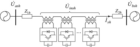
The DPFC can invert the voltage of different frequencies and compensate and eliminate the harmonics of the selected specific frequency. The DPFC is installed in the dual power supply ring distribution network, and the simplified circuit under a certain frequency doubling is shown in Figure 4.
Figure 4 shows that
When DPFC is used for harmonic control, the compensation voltage of DPFC is perpendicular to the line current, and the compensation phasor diagram is shown in Figure 5.
In Figure 5,
At this time, the harmonic power generated by the line is as follows:
Let
Equation 5 can be expressed as follows:
3 DPFC harmonic current suppression control strategy
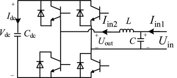
The primary equipment of the DPFC unit is a single-phase bridge voltage source converter generally composed of IGBTs. The equivalent circuit model is shown in Figure 6:
Figure 6 shows that
The mathematical model of DPFC in the rotating coordinate system can be expressed as follows:
After the Park transformation of the injected voltage
Among them,
The Laplace transform of Equations 12 and 13 is carried out, and the transformed equation is substituted in Equation 10 to obtain Equation 14:
The Laplace transform of Equations 12 and 13 is carried out, and the transformed equation is substituted in Equation 11 to obtain Equation 15:
From the harmonic suppression analysis Equation 8, it can be seen that in order to reduce the harmonic current amplitude within the capacity range of the DPFC device, the compensation voltage amplitude should be increased as much as possible, that is, the
As shown in Table 1, the total harmonic distortion rate of the voltage specified in the 0.38-kV distribution network needs to be controlled within 5%. According to the Newton–Raphson algorithm, the amplitude of the line harmonic current is judged first. If the harmonic current amplitude is less than 5%, the harmonic current does not need to be suppressed. The signal selection switch
The
Combined with the DPFC DC capacitor voltage control loop, voltage loop control, and current loop control, the complete control block diagram of DPFC in harmonic current suppression mode can be obtained, as shown in Figure 8.
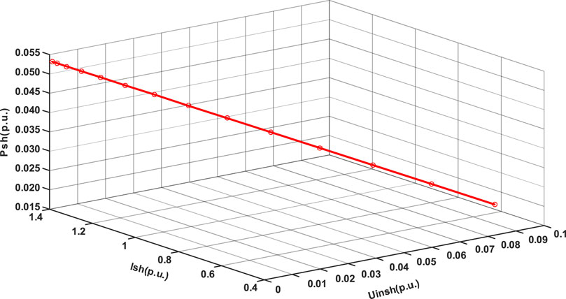
After determining the system parameters of the DPFC arranged on the line, the harmonic current suppression characteristics of the DPFC can be analyzed. The system parameters are set as follows:
It can be seen from Figure 9 that when the DPFC device does not perform harmonic current suppression, the initial harmonic power is 0.0534 (p.u.). As the DPFC output voltage increases from 0 to 0.091 (p.u.), both the harmonic current and the harmonic power decrease. The harmonic current suppression coefficient (denoted as) is (1.38791–0.5129)/0.091 = 9.615. At the same time, as the DPFC compensation voltage increases, the harmonic power decreases from 0.0534 (p.u.) to 0.0152 (p.u.). It shows that DPFC has a high regulation ability in suppressing the harmonic current.
The multiple DPFC units installed on the line can impose independent control targets on each DPFC, according to the different requirements of the capacity and voltage of the layout point so that it can track the given value of the instruction within its own capacity limit, and different DPFC units can also be redundant to each other, which greatly improves the stability and reliability of the whole system.
4 Simulation analysis of DPFC harmonic current suppression
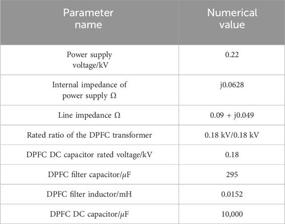
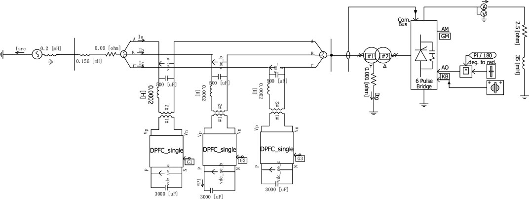
Based on PSCAD/EMTDC, a simulation model is built, as shown in Figure 10, to verify the effectiveness of the distributed power flow controller in controlling harmonics. The specific parameters of the model are shown in Table 2.
In the verification of the DPFC harmonic control, this paper uses a harmonic generator with a six-pulse rectifier as the core to inject sub-harmonics into the system. The simulation model built on the PSCAD/EMTDC platform is shown in Figure 11.
When the DPFC works in the harmonic current suppression mode, its controller module form is constructed in PSCAD, as shown in Figure 12.
When the DPFC harmonic current suppression simulation experiment is carried out in the system of Figure 11, the specific operation is as follows: 0.3 s is put into the DPFC device to charge the DC capacitor so that the DPFC is in a hot standby state. At 0.6 s, the DPFC device is put into the harmonic current suppression mode to suppress the harmonics injected into the line by the harmonic generation device. The current simulation waveform of the branch where the DPFC is located during the working process is shown in Figure 13. Among them, the fifth and seventh harmonics are taken as the representative, and the current waveform and amplitude change are shown in Figure 14 and Figure 15, respectively.
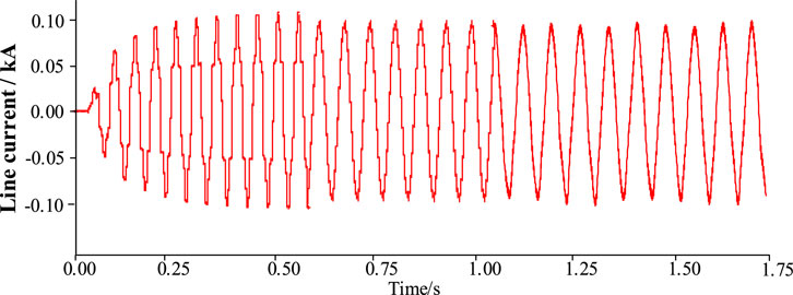
Figure 13. DPFC harmonic current suppression before and after the line single-phase current waveform.

Figure 14. The waveform and amplitude changes of the fifth harmonic current before and after the single-phase harmonic current suppression of DPFC are analyzed.
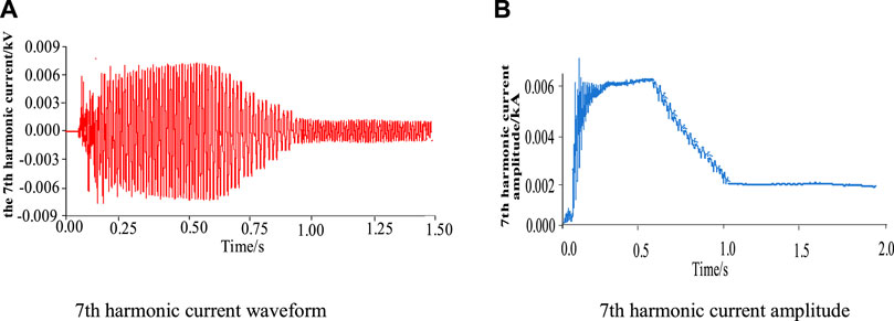
Figure 15. The waveform and amplitude changes of the seventh harmonic current before and after the single-phase harmonic current suppression of DPFC are analyzed.
As shown in Figure 13, under the harmonic injection of the harmonic generator within 0–0.5 s, the line current is seriously distorted into a non-standard sine waveform state because the DPFC does not input the harmonic current.
The waveform and amplitude of the fifth harmonic current before and after the harmonic current suppression of DPFC are changed.
As shown in Figure 13, under the harmonic injection of the harmonic generator within 0–0.5 s, the line current is seriously distorted into a non-standard sine waveform state because the DPFC does not input the harmonic current suppression mode, and its peak value is approximately 0.101 kV. At 0.6 s, the DPFC works to suppress the harmonic current, and the line current is restored to the sinusoidal state without harmonic distortion after a transition time of approximately 0.6 s. During the period, the amplitude of the line current is slightly reduced due to the filtering of the distorted harmonics and finally stabilized at the standard sinusoidal waveform state with a peak value of approximately 0.098 kV.
Compared with Figure 14 and Figure 15, when harmonic current suppression is not carried out, according to the previous formulas Equation 1 and Equation 4, it can be seen that when only the fifth and seventh harmonics are considered, the line current distortion rate 1 reaches 11.7%, of which the fifth harmonic content rate is 10.2% and the seventh harmonic content rate is 6.1%, indicating that the harmonic distortion rate at this time has exceeded the harmonic limit of the common grid specified in Table 1. After the harmonic current suppression of DPFC, the amplitude of the fifth harmonic current decreases from 0.01 kA to 0.003 kA, and the amplitude of the seventh harmonic current decreases from 0.006 kA to 0.002 kA. The harmonic content corresponding to the fifth and seventh harmonics is 3.06% and 2.04%, respectively, and the current distortion rate
The simulation results of the DPFC harmonic current suppression show that DPFC can effectively suppress the harmonic current and has a high suppression efficiency for fifth and seventh harmonic currents. At the same time, the simulation results also verify the correctness and effectiveness of the DPFC harmonic current suppression strategy proposed in this paper.
In addition, the control effects of the parallel PPF filter device, APF device, and DPFC device are compared by simulation. The parallel PPF includes two single-tuned filters and a band-pass filter. The simulation results are shown in Table 3.
The filtering effect after the installation of the parallel PPF device is better, and the main seventh harmonic filtering is more thorough, but the filtering effect for the fifth harmonic is not ideal, and the higher harmonics that account for a relatively small proportion are not effective. In addition, to a certain extent, it will cause changes in the grid-connected point voltage and current. After the APF device is installed, the overall filtering effect is weaker than that of the PPF device. After the installation of the DPFC device, the filtering effect is improved, compared with the previous two devices, and the filtering effect of the fifth and seventh harmonics is the best.
5 Conclusion
This paper summarizes the existing harmonic situation in the distribution network, analyzes the harmonic current and harmonic power in the dual power supply loop network in the distribution network in the form of a vector diagram and equivalent equation, and puts forward the distributed power flow controller as the way of harmonic control. The distributed power flow controller injects harmonic voltage sources of equal size and opposite direction into the distribution network to offset the harmonics in the distribution network and achieve the purpose of controlling the harmonics in the distribution network. The following conclusions are obtained:
1) After the harmonic current suppression of DPFC, the amplitude of the fifth and seventh harmonic currents decreased from 0.01 kA to 0.006 kA–0.003 kA and 0.002 kA, respectively, and the corresponding harmonic contents were 3.06% and 2.04 m%, respectively. The current distortion rate is reduced to 3.67%.
2) Due to the higher content of the fifth harmonic in the distribution network, the time required for its control based on the distributed power flow controller is more than that of the seventh harmonic.
3) The harmonic control technology based on DPFC effectively suppresses the harmonic content of the grid-connected point. Adding a new control algorithm to the DPFC device can make the harmonic reduction rate reach more than 98%.
It can be seen from the above that the distributed power flow controller has a good effect on the harmonic control of the distribution network. Since the distribution network is mostly segmented lines, which is in good agreement with the multi-module structure of the distributed power flow controller, each sub-module of the distributed power flow controller can be distributed in the line section of the distribution network, as needed to control the harmonic source locally.
In this paper, a harmonic suppression control strategy for the distribution network based on the distributed power flow controller is proposed, which provides a new idea for the problem of harmonic suppression and amplification caused by resonance in the distribution network and also provides theoretical support for the application of DPFC harmonic control engineering.
Data availability statement
The original contributions presented in the study are included in the article/supplementary material; further inquiries can be directed to the corresponding author.
Author contributions
CZ: writing–original draft and writing–review and editing. PQ: writing–original draft and writing–review and editing.
Funding
The author(s) declare that no financial support was received for the research, authorship, and/or publication of this article.
Conflict of interest
CZ and PQ were employed by Electric Power Research Institute of State Grid Zhejiang Electric Power Co, Ltd.
Publisher’s note
All claims expressed in this article are solely those of the authors and do not necessarily represent those of their affiliated organizations, or those of the publisher, the editors, and the reviewers. Any product that may be evaluated in this article, or claim that may be made by its manufacturer, is not guaranteed or endorsed by the publisher.
References
Chen, Ji, Zhang, X., and Yan, Z. (2021). Deadtime effect and background grid-voltage harmonic suppression methods for inverters with virtual impedance control. Trans. China Electrotech. Soc. 38 (8), 1671–1680.
Cheng, C. (2021). Research on harmonic suppression and resonant damping strategy of MMC-SAPF based on PSC-PWM. Wuhan, China Huazhong University of Science and Technology.
Geng, Y., Tian, F., and Sun, S. (2018). Harmonics suppression based on VSG. Trans. China Electrotech. Soc. 33 (5), 1040–1050.
Guo, H., Meng, X., and He, M. (2022). Smooth switching control strategy of microgrid without communication and high power quality. J. Electr. Technol. 37 (10), 2611–2621.
Li, G., Chen, Y., Luo, An, and Wang, H. (2020). An enhancing grid stiffness control strategy of STATCOM/BESS for damping sub-synchronous resonance in wind farm connected to weak grid. IEEE Trans. Industrial Inf. 16 (9), 5835–5845. doi:10.1109/tii.2019.2960863
Li, W., Zhang, G., and Zhong, H. (2022b). A high frequency resolution harmonic and interharmonic analysis mode. Trans. China Electrotech. Soc. 37 (13), 3372–3379.
Li, Y., Liu, P., and Hu, S. (2022a). Harmonic resonance suppression method of photovoltaic power station based on inductive filtering. Electr. Technol. J. 37 (15), 3781–3793.
long, Li, Liu, P., and Hu, S. (2022). Harmonic resonance damping method of photovoltaic power station based on inductive filtering. Trans. China Electrotech. Soc. 37 (15), 3781–3793.
Shen, H., Li, X., and Jia, K. (2019). Research on background harmonic attenuation strategy of annular distribution system based on two-point detection SRAPF. J. Sol. Energy 40 (2), 572–579.
Sun, Y., Zhang, P., Ke, D., Xu, J., and Liao, S. (2022). “Planning, design and optimal operation of energy Internet system under the condition of carbon peak,” China. South. Power Grid Technol. 16 (01), 1–13.
Tang, A., Song, X., Shang, Y., Guo, G., Yu, M., and Zhan, X. (2023). Harmonic mitigation method and control strategy of offshore wind power system based on distributed power flow controller. Auto. Electr. Power Syst. in press.
Tang, A., Yang, Y., Yang, H., Song, J., Qiu, P., Chen, Q., et al. (2022). Research on topology and control method of uninterrupted ice melting device based on non-contact coupling power flow controller. Proc. CSEE. in press.
Tang, A., Zhai, X., Lu, Z., Xu, Z., and Xu, O. (2021). A novel topology of distributed power flow controller for distribution network. Trans. China Electrotech. Soc. 36 (16), 3400–3409.
Wang, B., Yang, L., and Han, R. (2017). Position strategy of frequency division regulation resistive active power filter for annular distribution network. J. Electr. Technol. 32 (4), 241–249.
Wang, F., Zhou, B., and Zhang, H. (2022a). Under the background of 'double carbon', the coordination and interaction of source-grid-load-storage helps the construction of new power system. China, China 's Compr. Util. Resour. 40 (5), 188–191. 201.
Wang, H., Ren, Z., Gao, L., Hu, X., and Fan, M. (2022b). A four-terminal interconnected topology and its application in distribution network expansion planning. Int. J. Electr. Power Energy Syst. 141, 108177. doi:10.1016/j.ijepes.2022.108177
Xu, J., Cao, X., and Zhenyang, H. (2022). A harmoniccurrent suppression method for virtual synchronous rectifier based on feedforward of grid harmonic voltage. Trans. China Electrotech. Soc. 37 (8), 2018–2029.
Xu, M., Qin, S., Guang, F., Xue, Y., and Ma, J. (2021). “Analysis of harmonic characteristics of IIDG on small current grounding fault and its influence on line selection,” China. J. Power Syst. Automation 33 (01), 107–114.
Zhang, J., and ZhouQiang, W. D. (2021). “Research on the development path of new power system under the goal of 'double carbon',” China. Huadian Technol. 43 (12), 46–51.
Keywords: distributed power flow controller, harmonic control, distribution network, control strategy, fifth harmonic, seventh harmonic
Citation: Zhu C and Qiu P (2024) Harmonic suppression control strategy of distribution networks based on the distributed power flow controller. Front. Energy Res. 12:1355707. doi: 10.3389/fenrg.2024.1355707
Received: 14 December 2023; Accepted: 07 March 2024;
Published: 25 March 2024.
Edited by:
Shuqing Zhang, Tsinghua University, ChinaCopyright © 2024 Zhu and Qiu. This is an open-access article distributed under the terms of the Creative Commons Attribution License (CC BY). The use, distribution or reproduction in other forums is permitted, provided the original author(s) and the copyright owner(s) are credited and that the original publication in this journal is cited, in accordance with accepted academic practice. No use, distribution or reproduction is permitted which does not comply with these terms.
*Correspondence: Peng Qiu, MTUxOTU3NzU3MUBxcS5jb20=
 Chengzhi Zhu
 Peng Qiu


