 Dajiang Wang1
 Jianhui Meng
- 1State Grid Jiangsu Electric Power Company Ltd. Research Institute, Nanjing, China
- 2State Key Laboratory of Alternate Electrical Power System with Renewable Energy Sources, North China Electric Power University, Baoding, China
- 3State Grid Jiangsu Electric Power Company Ltd., Nanjing, China
In the context of the application of compressed air energy storage system participating in power grid regulation, a large capacity of compressed air energy storage accessed to or off from the power grid will bring instability to the system, and there will be voltage and current impact during off-grid operation, which will pose a threat to system security. Therefore, this paper puts forward the control strategy of compressed air energy storage for both grid-connected and off-grid, and proposes a smooth grid-connected strategy of compressed air energy storage based on adaptive PI control, which can better improve the problem of excessive impulse current during the connection of compressed air energy storage. Finally, a simulation model is built in MATLAB/Simulink to verify the effectiveness and superiority of the proposed control strategy.
1 Introduction
Compressed air energy storage, due to its large energy storage capacity and high conversion efficiency, is suitable for commercial application in large-scale energy storage power plants. It is one of the key technologies to solve the problems of volatile renewable energy consumption, power grid peak shaving, carbon compliance, and carbon neutrality (Mei S et al., 2017; Liu et al., 2023; Chen et al., 2016; Attarha et al., 2018). Compressed air energy storage has the characteristics of storing and converting three forms of energy: cold, heat, and electricity (R. Khatami et al., 2020). Through multi-energy cogeneration, high energy comprehensive utilization efficiency (70%–80%) can be achieved to make up for the lack of low power conversion efficiency of compressed air energy storage, thereby effectively improving the application economy of compressed air energy storage (A. Azizivahed et al., 2020).
In terms of the application of compressed air energy storage in power grid regulation, compressed air energy storage is used to smooth the fluctuations of wind power and improve the quality of wind power, so as to increase the utilization level of wind power and its penetration rate in the power grid (Cleary et al., 2015; Cheng et al., 2019; Zhu et al., 2023). Reference (Wen X et al., 2021) studies the participation of compressed air energy storage systems in primary frequency regulation and proposed a method for the compressed air energy storage system to participate bidirectionally in response to the primary frequency regulation of the power grid in the two stages of energy storage and energy release. Reference (Li G et al., 2021) proposes a phase modulation operation mode based on compressed air energy storage power plants, which achieves the function of supporting reactive power and voltage of the power grid and verifies the rationality of phase modulation operation of salt cavern compressed air energy storage power plants. Reference (Aldaadi et al., 2021) proposes a grid-connected power optimization strategy based on segmented real-time wind power and electricity price data averaging to ensure continuous and stable output of power to the grid. Reference (Xu W et al., 2022) proposes a new configuration that uses compressed air energy storage to assist wind turbines to increase the total power generation and schedulability of wind power generation, and verifies its effectiveness in realizing a schedulable wind energy conversion system through case studies. Reference (Meng et al., 2023) proposes a compressed air energy storage multi-energy co-supply system coupled with thermal power, evaluates its thermal performance and technical economy, and provides a new development idea for the large-scale commercial application of compressed air energy storage. Reference (Cheng J et al., 2018) proposed an advanced adiabatic compressed air energy storage multi-energy flow optimization scheduling model based on energy hub matrix modeling, proving that advanced adiabatic compressed air energy storage can realize daily hot spot joint supply and improve regional energy utilization efficiency.
Compressed air energy storage can operate independently with load and can also be connected to the power grid to participate in grid regulation. However, during the grid connection process, if the conditions of equal phase frequency to the grid voltage are not met, large impulse currents and voltages will usually be generated, threatening the safe and stable operation of equipment. Therefore, a smooth grid connection strategy is needed to ensure the smooth and safe connection of compressed air energy storage to the power grid. For smooth switching, reference (Xiong et al., 2016) adopts the methods of V/f control and PQ control switching, and introduces current compensation to reduce the transient impact before and after switching the control strategy. References (Wang et al., 2016; Zheng F et al., 2019) use a virtual synchronous generator to switch to PQ control, and controls the current loop instructions to ensure that the inner loop parameters are consistent when the control mode is switched to achieve smooth switching. Reference proposes a smooth grid connection strategy for optical storage virtual synchronous machines based on adaptive model predictive control. On the basis of the model predictive control strategy, frequency variation is introduced to adaptively adjust the weighting coefficient, which effectively improves the voltage and current surge problem during the switching process. Reference (Yuan et al., 2017) proposes a smooth switching control strategy for microgrid operation mode based on linear active disturbance rejection control technology, achieving the effect of quickly eliminating disturbances and smoothing the switching process. Reference (Xiong et al., 2016) proposes a new phase-locked loop suitable for microgrid systems based on the smooth switching control method of microgrid under master-slave control conditions to ensure smooth switching of microgrid operation modes and enhance system stability. At present, research on smooth switching focuses on microgrids, and there is little research on the issue of compressed air energy storage and smooth grid connection to reduce impulse voltage and current.
In order to solve the impact problem caused by the grid connection of compressed air energy storage, this paper proposes a smooth grid connection control strategy based on adaptive PI control after proposing control strategies for the compressed air energy storage system in both grid-connection and off-grid modes. Finally, a simulation model of compressed air energy storage was built on the MATLAB/SIMULINK simulation platform, and the proposed control strategy was experimentally verified.
2 Structure and modeling of compressed air energy storage system
Compressed air energy storage refers to the use of low valley electricity, wind power curtailment and photovoltaic power, etc., to compress the air through a compressor, and store high-pressure air in a sealed storage chamber. During peak electricity consumption period, the air is released to drive a turbine to generate electricity.
2.1 Structure of compressed air energy storage system
This paper builds an advanced adiabatic compressed air energy storage system, and the topology diagram of the system is shown in Figure 1. The system consists of an electric motor, a compressor unit, a gas storage tank, a heat storage system, an expansion unit, and a generator. During the low period of electricity consumption, surplus wind power is used to drive the compressor to compress the air through two stages of compression, generating high-temperature and high-pressure air that enters the heat exchanger on the compression side for heat exchange with the heat transfer oil. The heat transfer oil absorbs heat and heats up before entering the high-temperature heat transfer oil tank. The compressed air releases heat and cools down to the environmental temperature before entering the salt cavern gas storage tank for storage; During electricity peak period, high-pressure air is released from the gas storage, heated by high-temperature thermal oil in the oil-gas heat exchanger on the power generation side, and then enters the secondary air turbine with an intermediate reheater to expand and perform work to complete the power generation process (Shengwei et al., 2022).
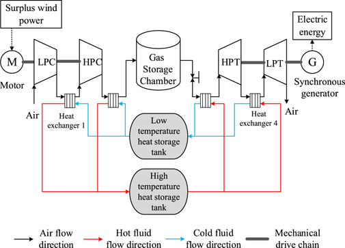
FIGURE 1. Topological structure of non-complementary compressed air energy storage system.
2.2 Modeling of compressed air energy storage system
This paper establishes a mathematical model for the operation of advanced adiabatic compressed air energy storage system under reasonable simplified conditions based on the thermodynamic, heat transfer, fluid mechanics, and electrical mechanisms of the main devices in the system (I. Calero et al., 2020; Mirzapour-Kamanaj et al., 2022). The mathematical model of each device is shown in Eqs 1–21.
1) Mathematical model of compressor
The continuous equation is as follows:
The compressor outlet air temperature equation is as follows:
The compressor power equation is as follows:
The compressor outlet pressure equation is as follows:
The number of compression stages is expressed as follows:
where mi. c and me. c are the air mass flow rates at the inlet and outlet of the compressor, kg/min; Ti. c and Te. c are the inlet and outlet air temperatures of the compressor, K; k is the specific heat ratio of air; ns is the adiabatic efficiency of the compressor; m is the air mass flow rate inside the compressor, kg/min; Nc is the input power of the compressor, kW; hi. c and he. c are the specific enthalpies of the inlet and outlet air of the compressor, kJ/kg; Pi. c and Pe. c are the inlet and outlet air pressures of the compressor, MPa; π is the single stage pressure ratio of the compressor, πz is the total pressure ratio of the compressor; S is the number of compressor stages.
2) Mathematical model of heat exchanger
The heat exchanger model in the energy storage stage is basically the same as the heat exchanger model in the energy release stage, with the difference being that the air in the heat exchanger during the energy storage stage releases heat, while the water absorbs heat; During the energy release stage, the air in the heat exchanger absorbs heat, while the water releases heat.
The air energy balance equation is as follows:
The metal heat storage equation is as follows:
The cooling water energy balance equation is as follows:
The heat transfer equation is as follows:
The energy efficiency equation is as follows:
The pressure drop equation is as follows:
Where, Ma, Mt, Mw are the air mass in the heat exchanger, the metal pipe mass of the heat exchanger, and the water mass inside the heat exchanger, kg; Cpa, Ct, and Cpw are the specific heat capacity of the air at constant pressure, metal tube specific heat capacity, and water specific heat capacity in the heat exchanger, kJ/(kg*K); m is the air mass flow rate inside the heat exchanger, kg/min; Gw. c is the mass flow rate of water inside the heat exchanger; Tai. c and Tae. c are the inlet and outlet air temperatures of the heat exchanger, K; Tt is the temperature of the metal tube of the heat exchanger, K; Twi. c and Twe. c are the temperatures of the inlet and outlet water in the heat exchanger, K; Q1 is the energy released by air, kJ; Q2 is the energy absorbed by water, kJ; α1 and α2 are the heat transfer coefficient of air and water, kJ/(m2*min*K); A is the heat exchange area, m2; ε is the energy efficiency of the heat exchanger; Pai. c and Pae. c are the air pressure at the inlet and outlet of the heat exchanger, MPa.
3) Mathematical model of gas storage tank
In this paper, the process of storing high-pressure gas in advanced adiabatic compressed air storage system is regarded as a constant volume process, energy is not released during storage, and air liquefaction is not considered. The pressure and temperature changes in the storage tank are mainly studied, and air is regarded as an ideal state.
The energy balance equation of gas storage tank in energy storage stage is as follows:
The energy balance equation of gas storage tank in energy release stage is as follows:
The change trend of air pressure and temperature in storage tank during energy storage stage is expressed as follows:
The change trend of air pressure and temperature in the tank during energy release is expressed as follows:
Where, Pv is the air pressure of the air storage tank, kPa; V is the volume of the air storage tank, m3; mc and ms are the air mass flow at the inlet and outlet of the air storage tank, kg/min; α3 is the heat exchange coefficient of the air storage tank, W/(m2*K); Mv is the gas mass in the air storage tank, kg; v is the internal energy per unit mass of the gas in the air storage tank, kJ/kg; AV is the heat exchange area of the air storage tank, m2; Th is the ambient temperature, K; Tvi and Tve are the air temperature at the inlet and outlet of the air storage tank, K; Cva is the specific heat capacity of air at constant volume, kJ/(kg*K); Rg is the gas constant, kJ/(kg*K). Tv is the air temperature in the tank, K.
4) Turbine mathematical model
The operation mechanism of turbine can be understood as the inverse process of compressor. The mathematical model of turbine is established by compressor modeling method.
The turbine outlet air temperature equation is as follows:
The turbine power equation is as follows:
The turbine outlet pressure equation is as follows:
Where, mi.s and me. s are the air mass flow at the inlet and outlet of turbine, kg/min; Ti. s, Te. s are the air temperature at the inlet and outlet of turbine, K; k is the specific heat ratio of air; ns is the adiabatic efficiency of turbine; m is the mass flow in turbine, kg/min; Ns is the output power of turbine, kW; hi. s and he. s are the air specific enthalpy at the inlet and outlet of turbine, kJ/kg; Pi. s and Pe. s are the air pressure at the inlet and outlet of turbine, MPa.
3 Compressed air energy storage smooth grid-connection strategy based on PI control
3.1 Grid-connected control structure and off-grid control structure of compressed air energy storage system
PQ control strategy is adopted when the compressed air energy storage system is connected to the grid, and V/f control strategy is adopted when the compressed air energy storage system is off the grid.
The coordinated control of grid-connected and off-grid modes enhances power supply reliability. Based on the above two control strategies, a control structure for compressed air energy storage systems operating in both grid-connected and off-grid modes is constructed, as shown in Figure 2.
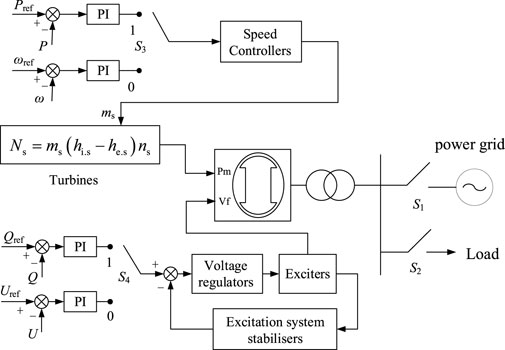
FIGURE 2. Grid-connected and off-grid control structure of compressed air energy storage system.
3.2 Control strategy of compressed air energy storage system connected to grid
PQ control strategy is adopted for grid-connected mode operation of compressed air storage. The fluctuation of load, frequency and voltage carried by compressed air storage are borne by the large power grid. Compressed air storage does not need to consider the regulation of voltage and frequency, but is directly controlled and regulated according to the voltage and frequency of the power grid. Compressed air storage outputs active and reactive power according to a given reference value. In this way, compressed air energy storage only needs to emit or absorb power, which can avoid interference to the power system caused by compressed air energy storage participating in voltage regulation of the power grid.
The active pow P output by that synchronous generator is compared with a reference value Pref to make a difference, then PI regulation is carry out, after PI regulation, the active power P enters a speed governor link to obtain air mas flow ms, ms is then input into a turbine for compressed air energy storage, wherein the turbine is equivalent to a prime mover in a conventional generator set, the air mass flow ms is equivalent to a steam valve opening of the turbine, and mechanical power Pm generated by expansion air of the turbine drives the synchronous generator to complete power generation. The process of generating power by compressed air energy storage system can be expressed by Equation 20.
The output reactive power Q and the reference value Qref of the synchronous generator are compared. After PI regulation, the excitation voltage of the exciter is obtained to control the output voltage of the exciter, that is, the excitation voltage Vf of the generator, and then input into the synchronous generator. In order to stabilize the operation of the excitation system and improve its dynamic quality, the negative feedback link of the excitation system is introduced, that is, the excitation system stabilizer, which is generally a soft feedback link, also known as speed feedback.
3.3 Off-grid control strategy for compressed air energy storage system
V/f control strategy is adopted for compressed air storage off-grid mode operation. When the power grid fails or scheduled maintenance occurs, the compressed air storage system needs to disconnect the common connection point with the power grid to realize off-grid operation, providing voltage and frequency support to ensure that the amplitude of frequency and output voltage is always controlled within the allowable range, regardless of how the output power changes, so as to ensure the normal and stable operation of the compressed air storage system off-grid.
When the compressed air energy storage system operates off-grid with V/f control strategy, the amplitude of output voltage V is obtained by measuring module, and then the frequency f is obtained by phase-locked loop. The amplitude of output voltage V is compared with reference value Vref, and then the excitation voltage Vf is obtained by exciter and input to synchronous generator. The frequency f is compared with the reference value fref, and after PI regulation, the air mass flow ms is obtained through the speed governor and input into the turbine for compressed air energy storage. The mechanical power generated by the turbine expansion air is used as the mechanical power Pm of the prime mover to drive the synchronous generator to complete power generation.
3.4 Compressed air energy storage smooth grid-connection strategy based on adaptive PI control
When the compressed air energy storage system is connected to the grid, the compressed air energy storage system voltage needs to be the same as the grid voltage in amplitude, phase and frequency. If the conditions cannot be met, there will be a large voltage difference when the grid switch is closed, which will lead to excessive grid impulse current and pose a threat to the system safety. Therefore, the output voltage of the compressed air energy storage system needs to match the grid voltage in amplitude, frequency and phase before grid-connection. In the voltage control of compressed air energy storage, the reference voltage has been set as the grid side voltage, so this paper mainly studies the control strategy of frequency and phase Angle. The control block diagram of compressed air energy storage smooth grid connection strategy based on PI control is shown in Figure 3.
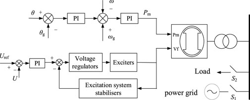
FIGURE 3. Compressed air energy storage smooth grid-connection strategy based on PI control.
In Figure 3, θ is the compressed air energy storage side voltage phase angle, θg is the grid side voltage phase angle, ω is the compressed air energy storage side angular frequency, and ωg is the grid side angular frequency. The phase difference between the compressed air storage output phase and the power grid is first controlled by PI, and its deviation value is introduced into the angular frequency deviation, and then Pm is obtained through PI control. This process can pre-synchronize the phase difference and frequency difference between the compressed air energy storage and the power grid, so that the phase difference and frequency difference between the compressed air energy storage and the power grid can be minimized when connected to the grid, so as to reduce the impulse current of the grid-connection.
In order to control the phase and frequency synchronization process of compressed air energy storage more accurately, the kp and ki parameters of PI regulator are adjusted adaptatively on the basis of PI control, so as to achieve the purpose of rapid response of the system and precise adjustment of phase and frequency pre-synchronization. kp and ki are proportional coefficients and integral coefficients respectively. The larger kp is, the faster the system responds, but too large kp will cause the instability of the system. ki improves the stability of the system, but the larger ki increases the overshoot and even the oscillation of the system. Therefore, in the pre-synchronization process, when the phase difference between the energy storage side and the network side is large, kp and ki are increased to improve the system response speed and reduce the pre-synchronization time. When the phase difference between the energy storage side and the network side is small, and the phase difference is close to the grid-connected requirements, in order to reduce the phase difference too fast and cause the system frequency instability, reduce kp and ki at this time. The adaptive PI control designed in this paper is shown in Eqs 22, 23:
In the formula, kp0 and ki0 are proportional coefficients and integral coefficients at the initial moment, respectively, which are set to 1 and 0.1; ∆kp and ∆ki are increments of scale and integration coefficients, respectively, set to 0.2 and 0.02, respectively.
4 Virtual inertial control based on fuzzy logic control
In order to verify the effectiveness of the grid connection and off-grid control strategies of the compressed air energy storage system and the smooth grid connection strategy of compressed air energy storage based on adaptive PI control, this section establishes the compressed air energy storage grid connection as shown in Figure 4 on the MATLAB/simulink platform. The system model verified the grid-connected and off-grid control strategies of the compressed air energy storage system and the smooth grid-connected strategy of compressed air energy storage based on PI control.
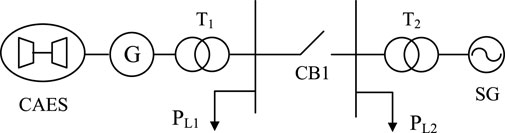
FIGURE 4. Compressed air energy storage grid-connected system topology.
In Figure 4, the rated power of compressed air energy storage is 200 MW, the rated voltage is 13.8 kV; the rated power of transformer T1 is 210MVA, the voltage level is 13.8/35 kV, the load PL1 is 150 MW; the rated power of the grid-side synchronous machine SG is 100 MW. The rated voltage is 13.8 kV; the rated power of transformer T2 is 210MVA, the voltage level is 13.8/35 kV, and the load PL2 is 10 MW. When the system starts, the compressed air energy storage adopts the PI control strategy shown in Figure 3 for pre-synchronization. When the phase angle difference between the compressed air energy storage and the grid side reaches the minimum, the grid is connected, and the compressed air energy storage control mode is switched to V/f control strategy and complete grid connection. The synchronous generator on the grid side adopts V/f control strategy before grid connection and PQ control strategy after grid connection.
Under the premise of the same system, the impulse voltage and current and phase Angle difference synchronization speed under adaptive PI control pre-synchronization and non-adaptive PI control are compared. In order to facilitate comparison, the output waveforms under different working conditions are displayed on the same interface. The compressed air energy storage and grid-side phase difference during the pre-synchronization and grid connection processes are shown in Figure 5.

FIGURE 5. Phase difference between compressed air energy storage and power grid.
As shown in Figure 5, when adaptive PI control is adopted to reduce the phase difference in the pre-synchronization mode, the phase difference between the compressed air energy storage and the network side will eventually be reduced to 0. The reason why the phase difference of the curve in the figure jumps to 0 is that the grid connection switch is closed at this moment, the compressed air energy storage is connected to the grid, the two run synchronously, and the phase difference becomes 0. By comparison, it can be found that the phase difference of compressed air energy storage and grid side will eventually be reduced to the value that meets the requirements of grid connection when adaptive PI control is used for pre-synchronization and non-adaptive PI control for pre-synchronization. However, the phase difference decreases faster under adaptive PI control, and the phase difference decreases to 0 at about 5.3s. When conventional non-adaptive PI control is adopted, the phase difference stabilizes at 12° at about 10s, and the phase difference reduction speed under adaptive PI control is obviously better than that under conventional PI control.
Figure 6 and Figure 7 show grid-connected current and grid-connected voltage under adaptive PI control and non-adaptive PI control. Due to the difference of grid-connection time between adaptive PI control and non-adaptive PI control, the time of impulse current and impulse voltage will be different. As can be seen from the figure, after grid-connection, the impulse current under non-adaptive PI control is about 3646A, and large amplitude oscillation occurs, and it takes about 1s to reach a stable state from the beginning of grid-connection. The impulse current under adaptive PI control is about 3420A, the oscillation amplitude is small, and it takes about 0.6 s from the beginning of grid connection to stability. As for the impulse voltage at the moment of grid connection, it can be seen from the voltage amplitude at the junction point in Figure 7 and the local amplification waveform in Figure 8 that the impulse voltage amplitude under adaptive PI control is smaller, the maximum impulse voltage is about 13.93kV, and the time taken to recover to stability is shorter, during which the voltage does not oscillate. However, the impact voltage amplitude under non-adaptive PI control is larger, and the maximum value of the impact voltage amplitude is about 13.96kV, and the recovery time is longer, and the voltage oscillates more seriously during the recovery.

FIGURE 6. Compressed air energy storage grid connection point current amplitude.

FIGURE 7. Compressed air energy storage grid connection point voltage amplitude.
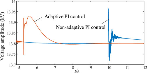
FIGURE 8. Partial amplification waveform of voltage amplitude at the compressed air energy storage grid-connection point.
Figure 9 and Figure 10 show the system frequency under non-adaptive PI control and adaptive PI control respectively. It can be seen from the figure that the system frequency under non-adaptive PI control will have a large oscillation amplitude at the grid-connected time, with the maximum oscillation exceeding 50.2 Hz and the minimum oscillation approaching 49.7 Hz. When adaptive PI control is adopted, the frequency oscillation amplitude of the system is small and there is no overshoot at the grid-connected time, and the maximum frequency is about 49.85 Hz during the oscillation process. It can be seen that the frequency stability is taken into account while the phase Angle synchronization is accelerated.
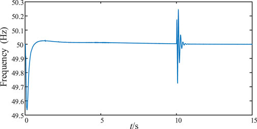
FIGURE 9. System frequency under non-adaptive PI control.

FIGURE 10. System frequency under adaptive PI control.
Based on the experimental results, it can be concluded that the smooth grid-connection strategy proposed in this paper based on adaptive PI control has a good control effect on the reduction rate of phase difference and the suppression of impulse current and voltage during the pre-synchronization process of compressed air energy storage grid-connection, and the voltage, current and frequency have smaller fluctuations when compressed air energy storage is connected to the grid, improving the safe and stable operation ability of the system.
5 Conclusion
Compressed air energy storage has broad application prospects. In order to reduce the impact current and voltage when compressed air energy storage is connected to the power grid and enable smooth grid-connection, this paper proposes a smooth grid-connection strategy based on adaptive PI control. The conclusions drawn are as follows.
1) A smooth grid-connection strategy based on adaptive PI control is proposed, which optimizes the frequency, phase and voltage response characteristics during the pre-synchronization process, reduces the impact current and voltage during compressed air energy storage connecting to power grid, and improves the ability of the system to operate safely.
2) Aiming at the problem of smooth grid connection of compressed air energy storage, a pre-synchronization strategy based on adaptive PI control is proposed, which can effectively solved the impact problem caused by mode switching during grid-connection and has good practical engineering application value.
Data availability statement
The raw data supporting the conclusion of this article will be made available by the authors, without undue reservation.
Author contributions
DW: Data curation, Writing–review and editing. YS: Investigation, Software, Writing–original draft. YG: Project administration, Resources, Writing–review and editing. JL: Methodology, Validation, Writing–review and editing. CY: Funding acquisition, Resources, Writing–review and editing. JM: Investigation, Writing–review and editing.
Funding
The author(s) declare financial support was received for the research, authorship, and/or publication of this article. This work was supported by the Science and Technology Project of State Grid Jiangsu Electric Power Company Limited (J2022064).
Conflict of interest
Author DW was employed by State Grid Jiangsu Electric Power Company Ltd. Research Institute. Authors YG, JL, and CY were employed by State Grid Jiangsu Electric Power Company Ltd.
The remaining authors declare that the research was conducted in the absence of any commercial or financial relationships that could be construed as a potential conflict of interest.
Publisher’s note
All claims expressed in this article are solely those of the authors and do not necessarily represent those of their affiliated organizations, or those of the publisher, the editors and the reviewers. Any product that may be evaluated in this article, or claim that may be made by its manufacturer, is not guaranteed or endorsed by the publisher.
References
Aldaadi, M., Al-Ismail, F., Al-Awami, A. T., and Muqbel, A. (2021). A coordinated bidding model for wind plant and compressed air energy storage systems in the energy and ancillary service markets using a distributionally robust optimization approach. IEEE Access 9, 148599–148610. doi:10.1109/access.2021.3123792
Attarha, A., Amjady, N., Dehghan, S., and Vatani, B. (2018). Adaptive robust self-scheduling for a wind producer with compressed air energy storage. IEEE Trans. Sustain. Energy 9 (4), 1659–1671. doi:10.1109/tste.2018.2806444
Azizivahed, A., Razavi, S. E., Arefi, A., Ghadi, M. J., Li, L., Zhang, J., et al. (2020). Risk-oriented multi-area economic dispatch solution with high penetration of wind power generation and compressed air energy storage system. IEEE Trans. Sustain. Energy 11 (3), 1569–1578. doi:10.1109/tste.2019.2931670
Calero, I., Cañizares, C. A., and Bhattacharya, K. (2020). Implementation of transient stability model of compressed air energy storage systems. IEEE Trans. Power Syst. 35 (6), 4734–4744. doi:10.1109/tpwrs.2020.2995787
Chen, L., Zheng, T., Mei, S., Xue, X., Liu, B., and Lu, Q. (2016). Review and prospect of compressed air energy storage system. J. Mod. Power Syst. Clean Energy 4 (4), 529–541. doi:10.1007/s40565-016-0240-5
Cheng, J., Li, R., Choobineh, F. F., Hu, Q., and Mei, S. (2018). Dispatchable generation of a novel compressed-air assisted wind turbine and its operation mechanism. IEEE Trans. Sustain. Energy 10 (4), 2201–2210. doi:10.1109/tste.2018.2883068
Cheng, J., Li, R., Choobineh, F. F., Hu, Q., and Mei, S. (2019). Dispatchable generation of a novel compressed-air assisted wind turbine and its operation mechanism. IEEE Trans. Sustain. Energy 10 (4), 2201–2210. doi:10.1109/tste.2018.2883068
Cleary, B., Duffy, A., OConnor, A., Conlon, M., and Fthenakis, V. (2014). “Assessing the economic benefits of compressed air energy storage for mitigating wind curtailment,” in IEEE transactions on sustainable energy 6 (3), 1021–1028. doi:10.1109/TSTE.2014.2376698
Khatami, R., Oikonomou, K., and Parvania, M. (2020). Look-ahead optimal participation of compressed air energy storage in day-ahead and real-time markets. IEEE Trans. Sustain. Energy 11 (2), 682–692. doi:10.1109/tste.2019.2903783
Li, G., Wang, G., Xue, X., Chen, L., et al. (2021). Design and analysis of condenser mode for jintan salt cavern compressed air energy storage plant of China. Automation Electr. Power Syst. 45 (19), 91–99. doi:10.7500/AEPS20210120006
Liu, X., Mei, S., Ding, R., et al. (2023). Current situation, development trend and Application Prospect of compressed air energy storage Project. Electr. Power Autom. Equip. 43 (10), 38–47+102. doi:10.16081/j.epae.202309005
Mei, S., Gong, M., Qin, G., et al. (2017). Advanced adiabatic compressed air energy storage system with salt cavern air storage and its application prospects. Power System Technology 41 (10), 3392–3399. doi:10.13335/j.1000-3673.pst.2017.1992
Meng, J., Zhang, Z., Zhang, G., Ye, T., Zhao, P., Wang, Y., et al. (2023). Adaptive model predictive control for grid-forming converters to achieve smooth transition from islanded to grid-connected mode. Transm. Distribution 17 (12), 2833–2845. doi:10.1049/gtd2.12859
Mirzapour-Kamanaj, A., Talebi, A., Zare, K., Mohammadi-Ivatloo, B., Abdul-Malek, Z., and Anvari-Moghaddam, A. (2022). Optimal look-ahead strategic bidding/offering of integrated renewable power plants and CAES with stochastic-robust approach. IEEE Access 10, 107901–107912. doi:10.1109/access.2022.3210033
Shengwei, M. E. I., Tong, Z., Xuelin, Z., et al. (2022). Research and engineering practice of non-supplementary combustion compressed air energy storage: taking Jintan national demonstration project as an example. Exp. Technol. Manag. 39 (05), 1–8. doi:10.16791/j.cnki.sjg.2022.05.001
Wang, M., Luo, An, Chen, Y., et al. (2016). The dual-mode control and seamless transfer control method of three-phase inverter. Trans. Chin. Soc. Electr. Eng. 31 (16), 124–134. doi:10.19595/j.cnki.1000-6753.tces.2016.16.015
Wen, X., Zhang, H., Yang, D., Zhong, J., and Feng, T. (2021). Research on the bidirectional participation of compressed air energy storage in primary frequency regulation of power grid. Autom. Instrum. 42 (12), 67–70+76. doi:10.16086/j.cnki.issn1000-0380.2021010071
Xiong, L., Zhuo, F., Wang, F., Liu, X., Chen, Y., Zhu, M., et al. (2016). Static synchronous generator model: a new perspective to investigate dynamic characteristics and stability issues of grid-tied PWM inverter. IEEE Trans. Power Electron. 31 (9), 6264–6280. doi:10.1109/tpel.2015.2498933
Xiong, L., Zhuo, F., Wang, F., Liu, X., Zhu, M., and Yi, H. (2016). A novel fast open-loop phase locking scheme based on synchronous reference frame for three-phase non-ideal power grids. J. Power Electron. 16 (4), 1513–1525. doi:10.6113/jpe.2016.16.4.1513
Xu, W., Zhang, W., Hu, Y., et al. (2022). Advanced adiabatic compressed air energy storage multi-energy flow optimization scheduling Model. Trans. China Electrotech. Soc. 37 (23), 5944–5955. doi:10.19595/j.cnki.1000-6753.tces.220772
Yuan, X., Lou, G., Liang, C., et al. (2017). Control strategy for microgrid seamless switching via linear active disturbance rejection. Power Syst. Technol. 41 (12), 3824–3831. doi:10.13335/j.1000-3673.pst.2017.0748
Zheng, F., Lin, X., Lin, Y., Zhang, Y., and Zhang, Y. (2019). Design of a novel hybrid control strategy for ES grid-connected inverter for smooth microgrid transition operation. IEEE Access 7, 171950–171965. doi:10.1109/access.2019.2955713
Zhu, J., Wei, C., Zhang, Y., Hu, D., Zheng, T., and Shan, L. (2023). “Thermal and electric characteristics of mine compressed air energy storage system based on stepped gas compression,” in 2023 5th asia energy and electrical engineering symposium (Chengdu, China: AEEES), 1722–1727. doi:10.1109/AEEES56888.2023.10114342
Keywords: compressed air energy storage1, grid-connected and off-grid control strategies2, smooth grid connection3, PI control4, impulse current5
Citation: Wang D, Sun Y, Ge Y, Li J, Yan C and Meng J (2024) A smooth grid connection strategy for compressed air energy storage based on adaptive PI control. Front. Energy Res. 12:1344749. doi: 10.3389/fenrg.2024.1344749
Received: 26 November 2023; Accepted: 04 January 2024;
Published: 16 January 2024.
Edited by:
Yonghui Liu, Hong Kong Polytechnic University, Hong Kong SAR, ChinaReviewed by:
Zhanghai Shi, Southwest Jiaotong University, ChinaChunyu Chen, China University of Mining and Technology, China
Zhengyang Xu, Tianjin University, China
Copyright © 2024 Wang, Sun, Ge, Li, Yan and Meng. This is an open-access article distributed under the terms of the Creative Commons Attribution License (CC BY). The use, distribution or reproduction in other forums is permitted, provided the original author(s) and the copyright owner(s) are credited and that the original publication in this journal is cited, in accordance with accepted academic practice. No use, distribution or reproduction is permitted which does not comply with these terms.
*Correspondence: Jianhui Meng, bWVuZ2ppYW5odWkyMDA4QDE2My5jb20=