 Geng Yiwa
 Liu Xiongbin2
- 1China Nuclear Power Engineering Co., Ltd., Beijing, China
- 2Institute of Nuclear and New Energy Technology of Tsinghua University, Beijing, China
- 3Shandong Institute of Advanced Technology, Jinan, Shandong, China
NHR-200-II is a small integrated pressurized water reactor with 200 MW core thermal power. The core heat is transferred to two independent intermediate circuits via fourteen in-vessel primary heat exchangers (PHE), and the heat in the intermediate circuits is transferred to feedwater by two steam generators (SG) in the two intermediate circuits respectively. A passive residual heat removal (PRHR) branch is connected to each intermediate circuit to remove core decay heat under postulated accidents. During normal operation, PRHR branches are isolated by valves while SG branches in intermediate circuits are open. The valves in PRHR branches will be opened and the isolation valves of SG branches will be closed during decay heat removal scenarios. The decay heat removal capacity of NHR-200-II PRHRS could be seriously deteriorated once the isolation valves for SG branches fail to close, which was confirmed in a scaled integral test loop previously. Current understanding of PRHRS’s thermal-hydraulic characteristics with possible isolation failure in SG branches is limited. In this paper, the NHR-200-II PRHRS is modeled with RELAP5 considering the case of success and fail to isolate SG branches. A series of numerical simulations are carried out to study the impact of various parameters, such as the initial temperature, the size of the intermediate circuits’ header, and the initial flow direction in the intermediate circuits. Oscillatory flow is found when SG branches fail to be isolated under certain parameters combinations. An improved PRHRS design is purposed to eliminate possible flow oscillations, and the purposed improved design are tested by numerical simulations.
1 Introduction
An integrated pressurized water reactor (IPWR) integrates major primary components inside the pressure vessel. IPWR is generally more compact than traditional PWR, and has higher safety level since it eliminates possible failures of the main primary pipes (Liu et al., 2023). Research and design of integrated pressurized water reactors is quite active in many countries, as shown in Figure 1. Korea’s system-integrated modular advanced reactor (SMART) has a power rating 330 MW, and the system design of SMART includes both inherent and passive safety systems. In the United States, there are many IPWR designs such as mPower, NuScale, Westinghouse SMR, et al. In addition, CAREM-25 reactor in Argentina, Flexblue reactor by DCNS group in France and ABV-6M, RITM-200 reactors designed by Russia are integrated pressurized water reactor designs (IAEA, 2012).
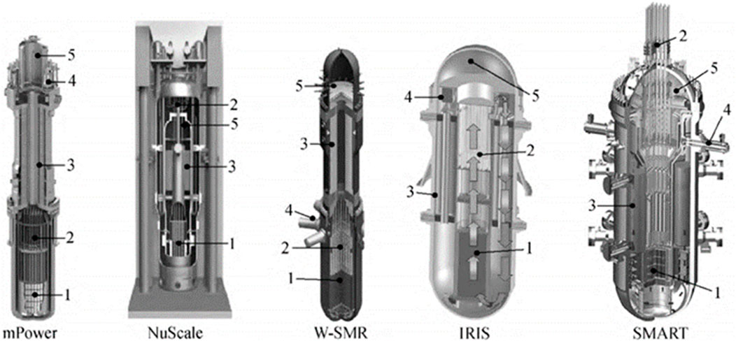
Figure 1. Small integrated pressurized water reactor under development in the worldwide. (Copyright permission has been obtained before use).
NHR-200-II nuclear heating reactor is a multi-purpose small integrated pressurized water reactor developed by the Institute of Nuclear and New Energy Technology (INET) of Tsinghua University (Wang et al., 1993). The NHR-200-II design characteristics include a tri-circuits design, hydraulic control rod driving systems, in-vessel pressurizer with vapor and nitrogen, and passive residual heat removal systems (PRHRS). The NHR-200-II design has many advantages like higher safety, compact size, and controllable investment, make the reactor widely-deployable in many areas, like urban heating, seawater desalination, nuclear powered icebreakers, etc.
The PRHRS is an important safety system for NHR-200-II nuclear heating reactor. The PRHRS relies on three coupling natural circulations to remove core residual heat, namely the natural circulation of primary side in the reactor pressure vessel (RPV), the single-phase natural circulation in RHE branches of the intermediate circuits, and the natural circulation of air in the cooling tower (Zhang et al., 1993). However, flow instability in PRHRS was unexpectedly observed in a scaled integral test facility built for nuclear heating reactors, and the flow instability occurred when the isolation valves of SGs in the intermediate circuits failed to close (INET, 2018). Current understanding of the transient characteristics of NHR-200-II PRHRS with isolation failure in SG branch is quite limited.
The earliest studies on the instability of single-phase natural circulation loop (NCL) were focused on the oscillation mechanism in several typical simplified loops. Keller (Keller and Joseph, 1966) predicted the one-way oscillation without flow reversal by studying the rectangular loop with heat source and radiator in the center of the horizontal pipes at the bottom and top, and predicted the one-way instability flow in rectangular NCL with point-type heat source/sink. Keller first found that simplified rectangular loop flow have cyclic periodic motion theoretically. Welander (Welander, 1967) pointed out that a loop with two vertical branches, a point heat source at the bottom and a point heat sink at the top, may have unstable behavior at certain heat power inputs. Welander also provided a physical explanation for the instability by the motion of “warm and cold pockets of fluids.” Welander’s conclusion was validated by Creveling (Creveling et al., 1975), who first observed the instability in an annular water loop.
The initial flow direction in a closed NCL may have significant impact on the steady-state behavior of the NCL. Sen and Trevino (Sen and Trevino, 1982) proved that an NCL can have both positive and negative steady-state flow rates, depending on the initial NCL conditions. The heat input history and initial thermal condition will also affect the flow distribution in a NCL with multiple parallel branches. Takeda (Takeda et al., 1987) studied a parallel-channel NCL with different heat inputs experimentally and theoretically, and found that flow direction and flow rate of each channel depend on the historical effect of heat input in each channel. Gartia et al. (Gartia et al., 2006) studied a NCL with three non-uniformly heated parallel channels and a common cold leg by a RELAP5 model, the existence of a metastable state of the parallel-channel NCL was confirmed, and the influence of different parameters on the metastable state was studied theoretically and numerically.
In our related series research on NHR-200-II, it was found that the cold and hot ring header of PRHR system would have obvious flow thermal stratification phenomenon (Geng et al., 2023), which would affect the flow stability and distribution. Thermal stratification effect in the headers of the PRHR system played an important role in the phenomenon of uneven outlet temperature distributions. In the previous study (Geng et al., 2023), the research focusses on reproducing the three-dimensional flow field effect of the cold and hot ring pipe. In this paper, the perspective of numerical model verification related research work also carried out, analyzes the influence of hot and cold ring pipe and Y-junction on the PRHR system, and an improved design was proposed.
In this paper, a RELAP5 model is built to study the transient characteristics of the PRHRS in a scaled integral test facility for nuclear heating reactors. The steady-state simulations under different core temperatures are performed first. Both the case of success and fail to isolate the SGs branches are investigated. Impact of various design parameters, such as header size of the intermediate circuits, initial flow direction of intermediate circuits, are studied numerically with the RELAP5 model. An improved PRHR design for the NHR-200-II reactor is proposed to suppress possible oscillatory flow in the original PRHR design.
2 Materials and methods
2.1 Design of PRHRS of NHR-200-II
The NHR-200-II PRHRS has two identical heat removal columns, and a simplified schematic diagram of PRHRS is shown in Figure 2. Each PRHR column consists of: (1) seven in-vessel primary heat exchanger (PHE) branches, (2) a residual heat exchanger (RHE) branch with the RHE placed in an air-cooling tower, (3) a pressurizer (PRZ), (4) a SG branch, (5) a hot ring header and a cold ring header above the pressure vessel, and (6) two isolation valves in the SG branch and another two isolation valves in the RHE branch.
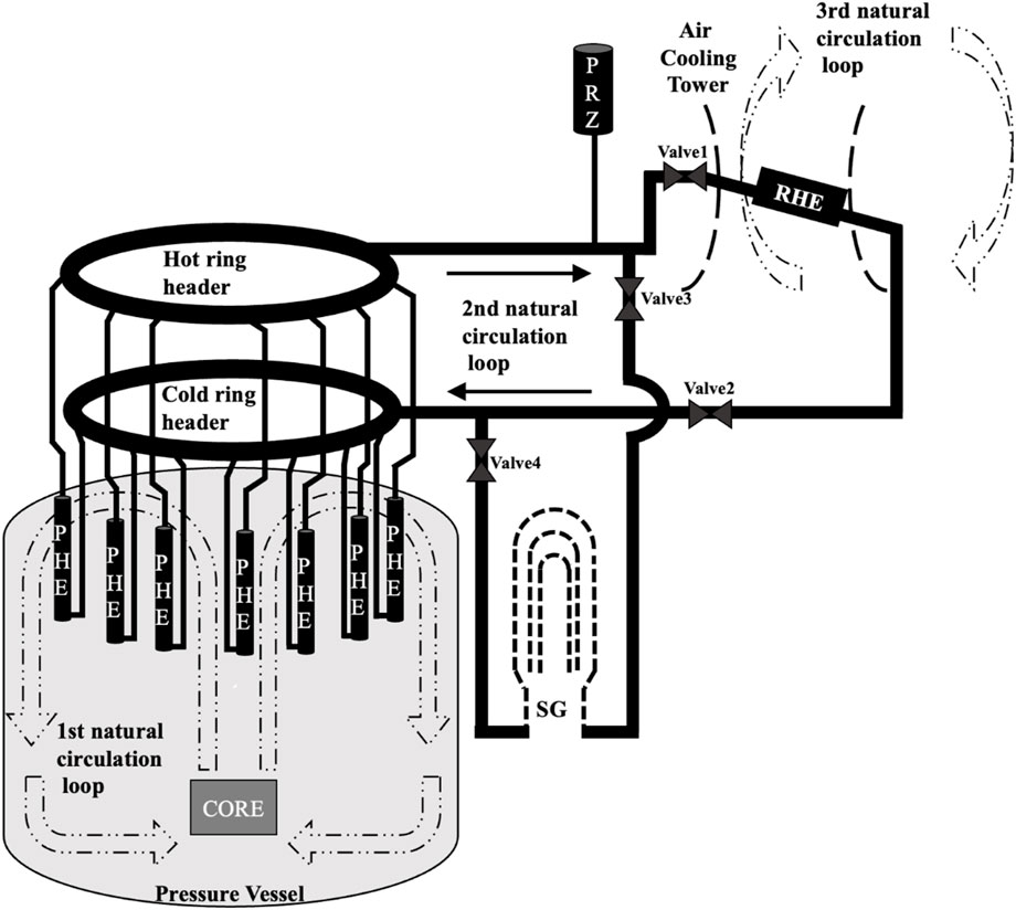
Figure 2. Schematic diagram of one column of PRHRS.
The RHE is a finned-tube air cooler located in the air-cooling tower of NHR-200-II. The cold ring header and hot ring header are coaxially arranged above the reactor pressure vessel. PHEs are connected to the headers by T-shaped tees asymmetrically, and the RHE is connected to the headers by low resistance Y-shaped tees. The PRZ is placed at the highest location of the loop.
The PRHRS utilizes three coupled natural circulations loops to remove core residual heat passively. The first loop is natural circulation of the primary fluid within the reactor pressure vessel. The second loop is the fluid circulation in the residual heat removal loop (Figure 2), and the third loop is natural circulation of air in the air-cooling tower.
Under normal operating conditions, valves in the RHE branch (Valve1 and Valve2 in Figure 2) are closed, and core heat is transferred from the seven in-vessel PHEs to the SG. Under reactor shutdown or postulated accidents, valves in the RHE branch (Valve3 and Valve4 in Figure 2) are opened, and decay heat is transferred from the PHEs to the RHE. However, the Valve1 and Valve2 may fail to close during PRHRS operation. In such scenarios, the RHE branch and SG branch will operate simultaneously to remove the core decay heat. The PRHRS should maintain the heat removal capacity upon isolation failure of Valve1 or Valve2 according to the single failure criteria.
2.2 The RELAP5 model
A RELAP5 model is developed for the PRHRS of the integral test facility. The model consists of six PHE branches (components number starting with 1–6 in the model), a cold ring header (components number starting with 7), a hot ring header (components number starting with 8), an RHE branch and a SG branch (components number starting with 9). The six PHE branches are evenly connected between the cold and hot ring headers in the circumferential direction. The RHE branch is connected to the cold ring header between PHE-1# and PHE- 2#. The RHE branch as well as SG branch is connected to the hot ring header between PHE-1# and PHE-6#, as shown in Figure 3. Four valves labeled as V1, V2, V3, and V4 are placed in the system, which can be switched on/off upon RELAP5 input cards.
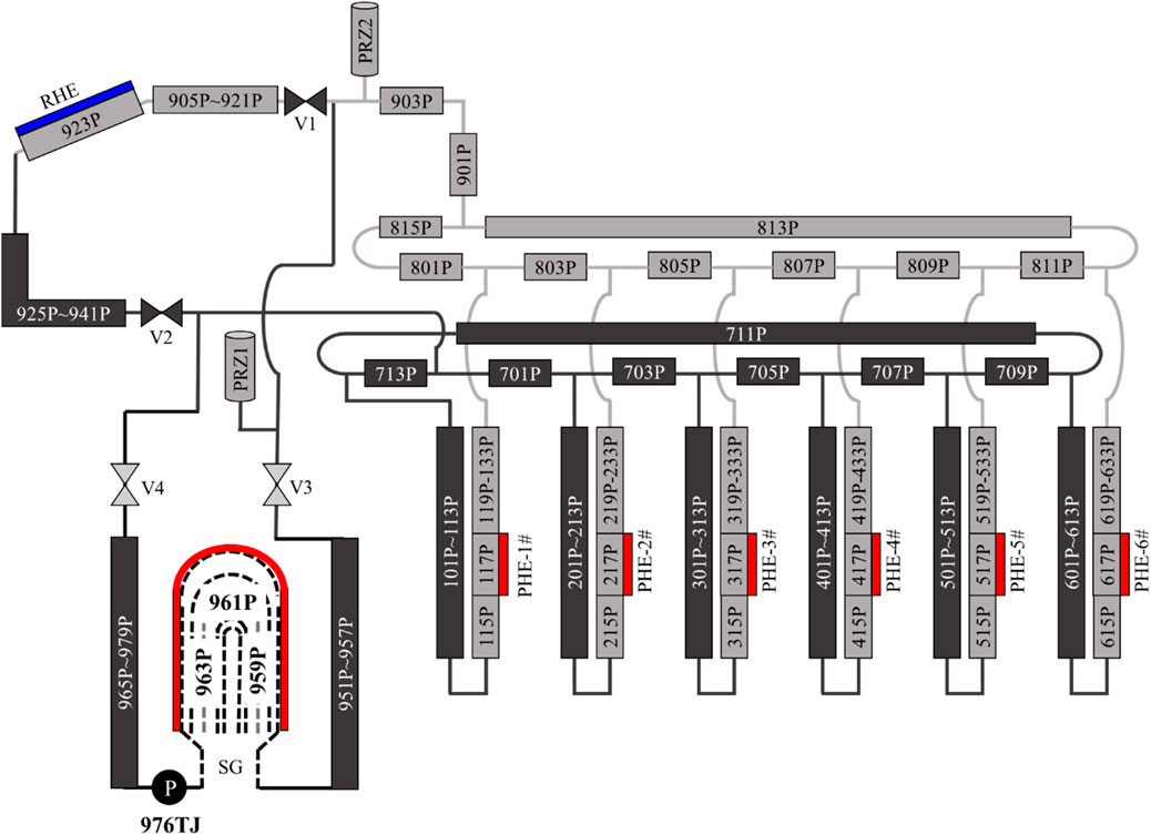
Figure 3. RELAP5 model of the PRHRS in integral test facility for NHR-200-II.
RELAP5 input deck involves a variety of hydraulic components, including the initial calculation value, such as temperature, pressure, mass flow rate, and other thermal hydraulic parameters and calculation model. The facility design value was used as the initial state calculation value, and adjusted the input deck to the steady state before the calculation.
The PHE used in the NHR-200-II facility adopts a ring tube bundle structure with double casing. Simplified pipes are used in the Relap5 model to simulate the flow channel in the ring gap space of the tube bundle. The secondary side fluid flows in the middle gap of the ring tube, and the primary side fluid flows in the outsides and inside of the ring gap. Different constant temperatures are set as the thermal boundary in the heat structure, and different temperature values ranging from 533.15 to 327.15 K are used in different cases.
The U-shaped heat transfer tube bundle in SG is modeled by section, the secondary side is simulated by heat structure, and the thermal boundary is set as 453.15 K constant temperature.
The RHE heat transfer tube also uses a single pipe to simulate the heat transfer bundle, the heat structure simulates the secondary side, and the constant temperature thermal boundary 298.15 K is calculated.
3 Results
3.1 Impact of primary fluid temperature on the PRHRS transient characteristics
The transient characteristics of PRHRS is simulated with the primary fluid temperature varying from 327.15 K to 533.15 K. The RHE heat sink temperature is kept at 298.15 K and SG boundary temperature is kept at 453.15 K in all cases.
In this study, the operation curve of the PRHRS is divided into three stages. The first stage is the normal operation mode with all the PHE branches and the SG branch connected, where the valves of V1 and V2 are closed and the valves of V3 and V4 are opened. The SG branch is driven by the pump 976TJ, where the mass flow rate of pump is increased from zero to a maximum of approximately 31.95 kg/s and remained at the maximum for a period.
In the second stage, the RHE branch is put into operation by opening V1 and V2 while the V3 and V4 are kept open, the purpose of second stage is to simulate the transient characteristics of PRHRS in case of fail to isolate the SG branch.
In the third stage, the SG valves named V3 and V4 are closed and the SG branch is isolated successfully, and core decay heat is transferred from the PHEs to the RHE. The third stage is set to simulate the standard PRHRS operation mode.
A series of numerical simulations with different primary fluid temperature are conducted to simulate the impact of primary fluid temperature on the PRHRS transient characteristics. Figure 4 shows the transient mass flow rate of each branch at different primary fluid temperatures.
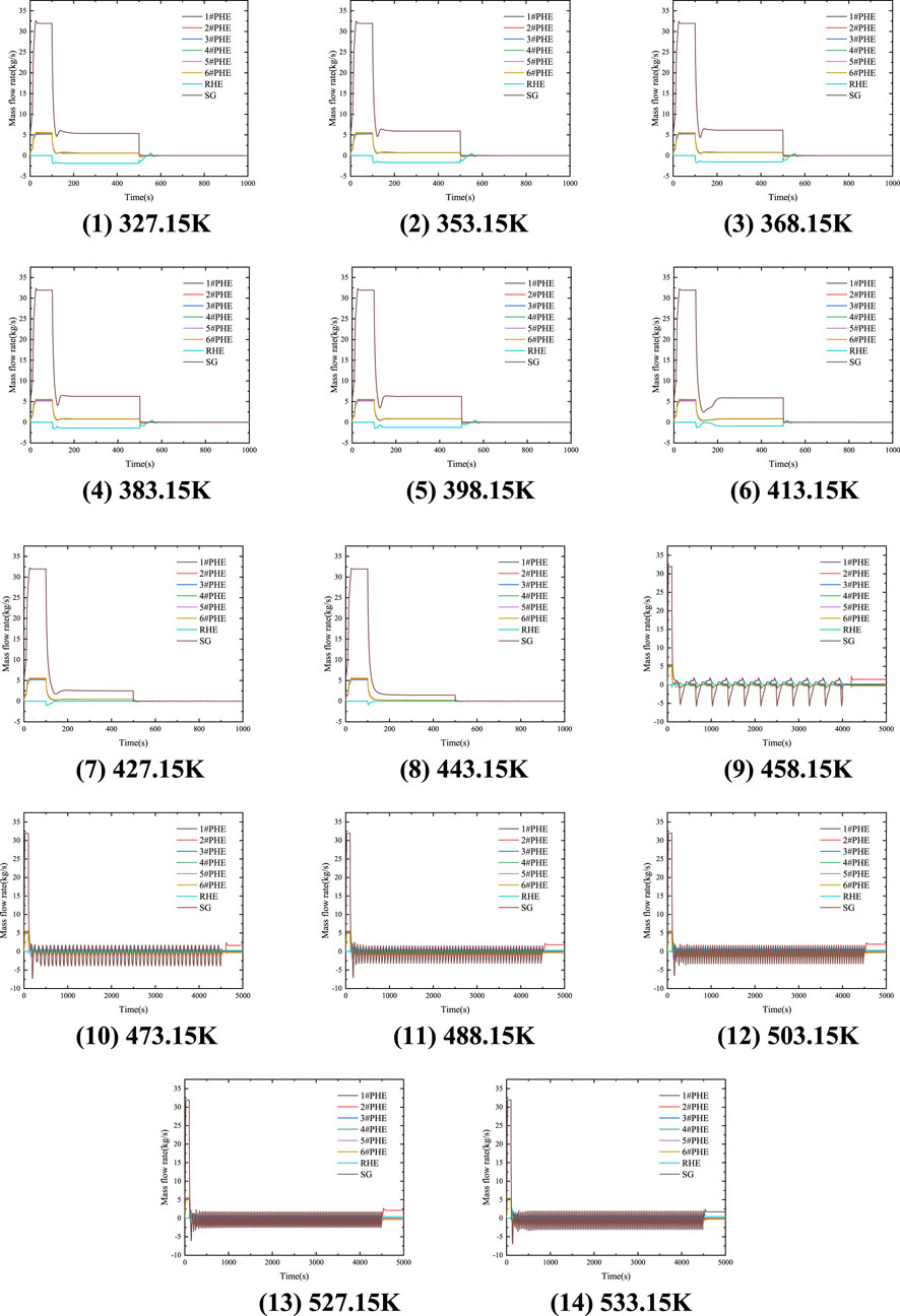
Figure 4. Transient mass flow rate of each branch at different primary fluid temperature.
When the core temperature is range between 327.15 K and 413.15 K, a steady-state flow distribution is achieved in the second stage. In this stage, the steady-state flow rates of each branch with the primary fluid temperature are shown in Figure 5, where the mass flow rate of SG branch is denoted as M1, the totally mass flow rate of six PHE branches is denoted as M2, and the mass flow rate of RHE branch is denoted as M3. With the increase of primary fluid temperature from 327.15 K to 413.15 K, the mass flow rate of RHE branch increases monotonically, while the mass flow rate of PHE branches and the SG branch first increase and then decrease.
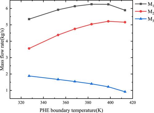
Figure 5. Mass flow rate with different PHE temperature in second stage Stable conditions.
For the middle temperature range of 413.15 K–458.15 K, the transient flow characteristics is different, where the flow in RHE branch is suppressed in the second stage completely.
For the core temperature range of 458.15 K–533.15 K, it can be seen from Figure 4 that unstable oscillating flow will occur in the second stage, which means the heat removal capacity of the PRHRS may be significantly deteriorated when the SG branch is failed to be isolated. In contrast, the PRHRS reaches a steady state in the third stage where the SG branch is isolated.
3.2 Effect of hot and cold ring header on the transient characteristics of PRHRS
The hot and cold ring header are important to the PRHRS hydraulic characteristics. In order to investigate the effect of ring headers on the oscillatory flow during the second stage, the ring headers in the original model (Figure 2) are replaced with small control volumes represented by the 714B and 814B (Figure 6). For the RELAP5 model of Figure 6, the transient flow rates of each branch at different primary fluid temperature are shown in Figure 7.
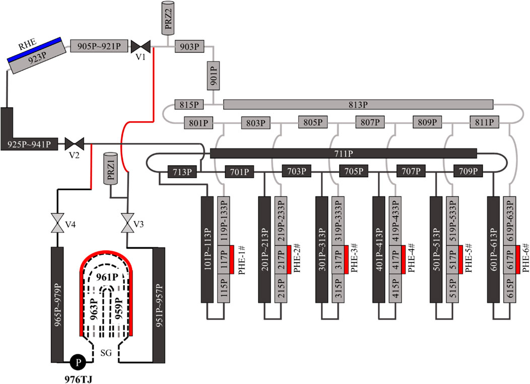
Figure 6. RELAP5 node diagram of the PRHRS of removing ring header.
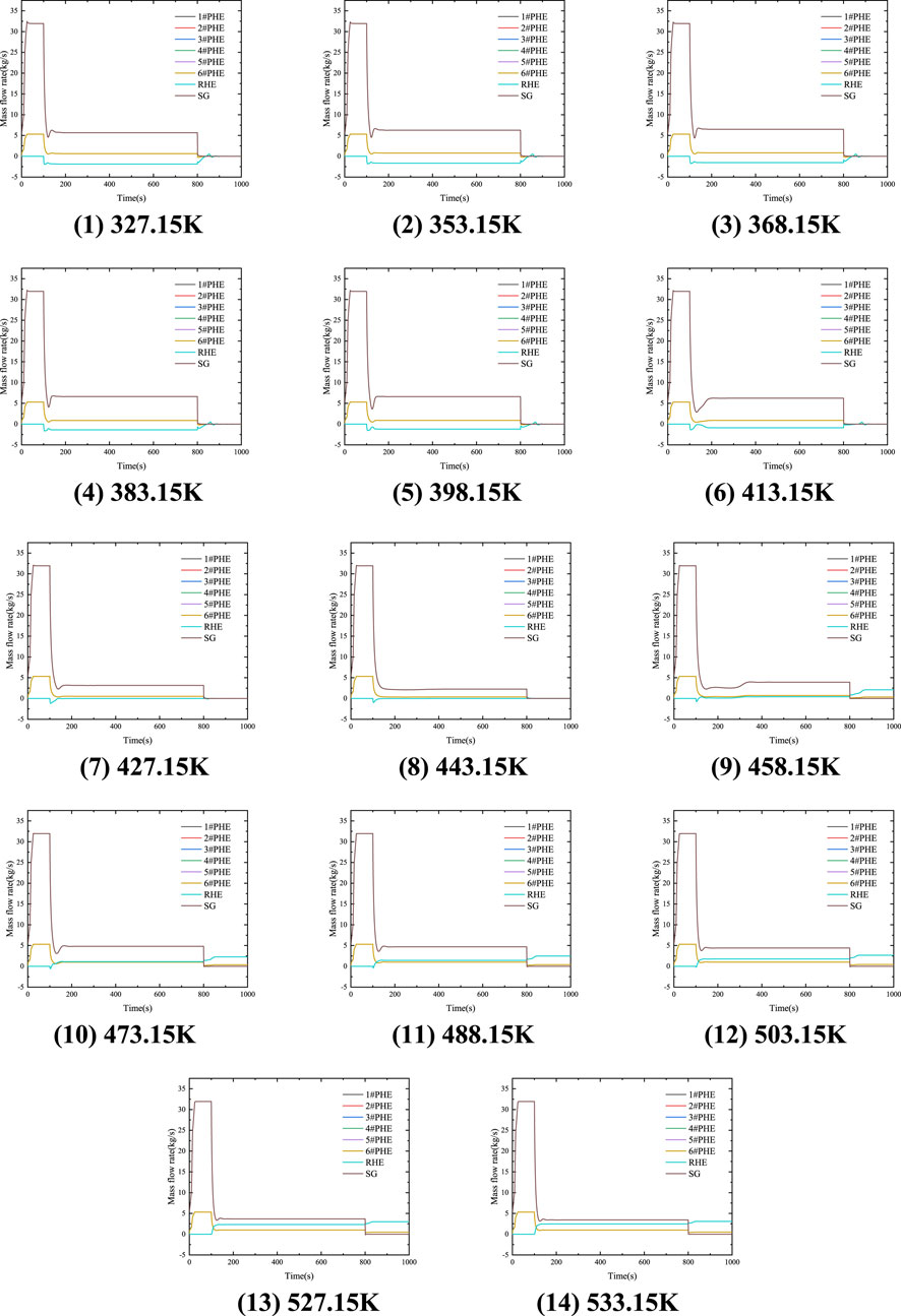
Figure 7. Mass flow rate of each branch changing with Time at different PHE boundary temperature (removing the ring header).
For the primary fluid temperature range of 327.15 K–413.15 K, steady-state flow distribution is also achieved in the second stage. The flow rate distribution without ring headers is compared to the flow rates of the original model in Figure 8. It can be seen from Figure 8 that the steady-state flow rate of each branch has the same trend for the two models with and without ring headers, the flow rate of SG branch and PHE branches of the model without ring headers is slightly higher than that of the original model, while the mass flow rate of RHE branch is not significantly changed.
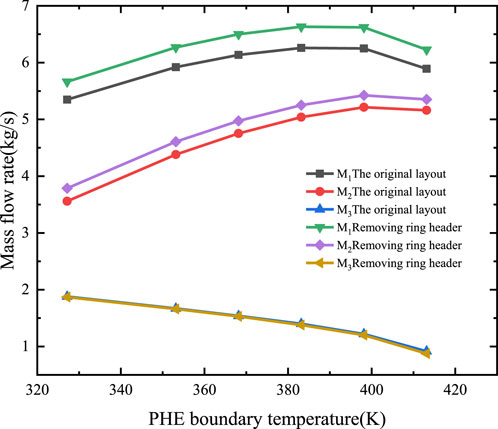
Figure 8. Mass flow rate at different primary fluid temperature under second stage (with the ring headers removed).
For the temperature range of 413.15 K–458.15 K, the transient flow characteristics of the system model without ring headers is generally the same to the original RELAP5 model. However, in temperature range of 458.15 K–533.15 K, steady-state flow distributions are achieved instead of the oscillatory flow of the original model in the second stage, which indicates that removing ring headers can suppress the oscillatory flow when isolation valves of the SG branch fail to close. In the third phase, with the absence of ring header, the flow distribution of six PHE branches are uniform, and the reverse flow phenomena in the six PHE branches caused by the existence of ring headers is eliminated.
3.3 Effect of initial flow rates to the transient characteristics of PRHRS
In order to study the influence of the initial flow rates to the steady-state flow rate distribution of all PRHR branches, the flow direction of pump 976 TJ is set to the opposite direction in the first stage. The transient flow rate of each branch is shown in Figure 9.
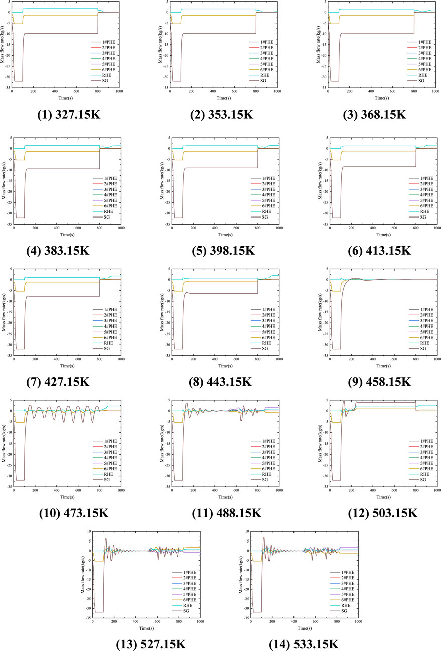
Figure 9. Transient flow rate of each branch at different primary fluid temperature (with reversed initial flow direction of SG pump).
For the primary fluid temperature range of 327.15 K–443.15 K, the steady-state flow rates of the second stage of the current model (Figure 9) are opposite to that of the original model (Figure 4). The absolute value of steady state flow rates of PRHR branches for the current model and the original model are plotted on Figure 10, where the flow rate of SG branch (M1) and all PHE branches (M2) are significantly higher than the flow rates of the original PRHRS model or the PRHRS model without ring headers, while the flow rate of RHE branch (M3) is almost unchanged.
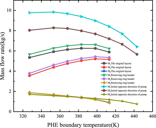
Figure 10. Steady-state flow rate at different primary fluid temperature in the second stage (with reversed initial flow direction of SG pump).
For higher primary fluid temperature ranges from 473.15 K to 533.15 K, oscillating flow also occurs in the second stage of PRHRS operation for the current model with initial SG pump flow direction reversed. However, it can be seen from Figure 10 that the pattern of oscillatory flow is very different compared to the transient flow rate of the original model (Figure 4). Therefore, the initial flow direction of PRHRS has a significant influence on the transient flow characteristics of PRHRS.
3.4 A preliminary PRHRS design improvement to suppress oscillatory flow
The flow oscillation phenomena, which may occur in PRHRS when the isolation valves of SG branch fail to close in certain temperature ranges, could significantly deteriorate the heat removal capacity of the PRHRS. A preliminary PRHRS design improvement to suppress the oscillatory flow is proposed and shown in Figure 11, where the tees of the SG branch are moved from the RHE branch (Figure 3) to the ring headers (Figure 11). The general consideration behind this design improvement is to reduce the flow resistance from the six PHE branches to the SG branch, and to avoid early mixing of fluid with different temperatures from both the RHE branch and the SG branch.
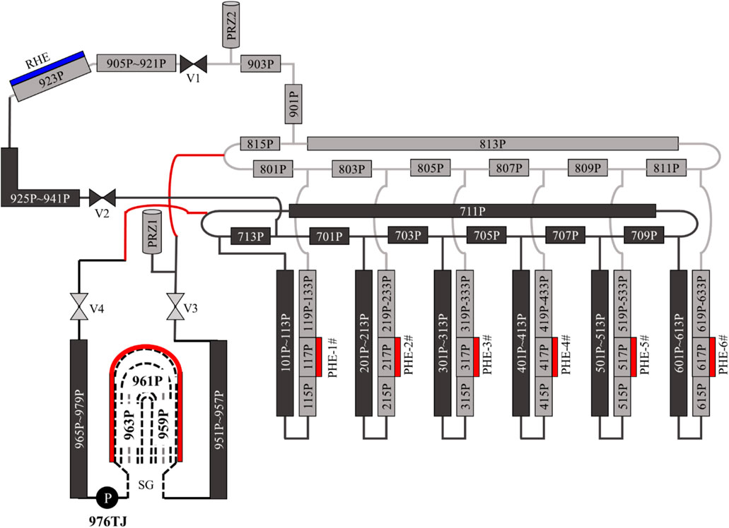
Figure 11. RELAP5 node figure of an improved PRHRS design.
The transient flow rate of the improved design is shown in Figure 12 with primary fluid temperature of 533.15 K. The operation curve of PRHRS used in this section is the same as previous sections, i.e., the first stage (0–50 s) with pump-driven circulation between SG and the six PHEs, and the second stage (50–550 s) with valves of RHE branch opened and valves of SG branch kept open (isolation failure), and for the third stage (550–1000 s), the SG branch is isolated.
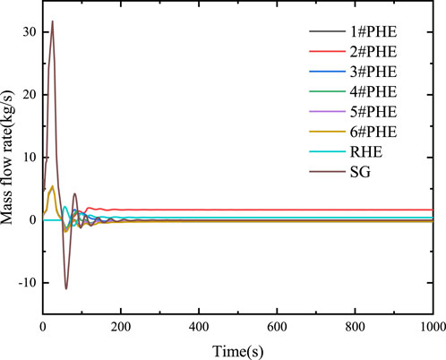
Figure 12. Transient flow rate of the improved design with primary fluid temperature of 533.15 K.
As can be seen from Figure 12, the steady-state flow rate of all branches in the second stage (50–550 s) is the same as the third stage (550–1,000 s), which indicates that the improved PRHRS design can effectively suppress the flow oscillations during the period of isolation failure of SG valves. However, study of the purposed design improvement is preliminary and further numerical simulations and experiments are needed to confirm the effectiveness of the improved PRHRS design.
4 Discussion
In this paper, a RELAP5 model is established for the NHR-200-II nuclear heating reactor PRHRS integral test facility. The impact of various parameters on PRHRS transient flow characteristics are studied, the parameters include the primary fluid temperature, the existence of ring headers and the initial flow directions. Both the case of fail and success to isolate SG branch are considered. The main conclusions include:
(1) The flow rates in PRHR branches are always steady when success to isolate SG branch, and the flow in PRHRS is oscillatory when fail to isolate SG branch if the primary fluid temperature is larger than 458.15 K.
(2) The flow oscillation can be suppressed by replacing the ring headers with a small control volume in the RELAP5 model. This means that the design of ring headers is an important cause on flow instability. In the RELAP5 model without ring headers, the steady-state flow rates of the SG branch and the six PHE branches are larger than that of the original model.
(3) The initial flow direction of PRHRS has a significant influence on the transient PRHRS flow characteristics. In a lower primary fluid temperature range of 327.15 K–443.15 K, the steady-state flow rates are opposite to the original model once the initial flow direction of SG branch is reversed. The SG branch and all PHE branches absolute value steady state flow rates increase when the initial flow direction of SG branch reversed, while the flow rate of RHE branch is almost unchanged.
(4) A preliminary improvement of PRHRS design is purposed, where the tees of SG branch are moved from the RHE branch to the ring headers. Preliminary numerical results show that the flow oscillations are effectively suppressed when fail to isolate SG branch. Further numerical simulations and experiments are planned to confirm the effectiveness of the improved PRHRS design.
Data availability statement
The original contributions presented in the study are included in the article/Supplementary material, further inquiries can be directed to the corresponding authors.
Author contributions
GY: Writing–review and editing, Writing–original draft, Visualization, Validation, Software, Methodology. LXb: Writing–review and editing, Resources, Funding acquisition, Conceptualization. LZ: Data curation, Formal Analysis, Writing–review and editing. HS: Writing–review and editing, Methodology, Investigation. ZL: Data curation, Writing–review and editing. XY: Writing–review and editing, Supervision. LXt: Writing–review and editing, Resources, Project administration. ZY: Funding acquisition, Project administration, Resources, Writing–review and editing.
Funding
The author(s) declare that no financial support was received for the research, authorship, and/or publication of this article.
Conflict of interest
Authors GY, HS, ZL, and XY were employed by China Nuclear Power Engineering Co., Ltd.
The remaining authors declare that the research was conducted in the absence of any commercial or financial relationships that could be construed as a potential conflict of interest.
Publisher’s note
All claims expressed in this article are solely those of the authors and do not necessarily represent those of their affiliated organizations, or those of the publisher, the editors and the reviewers. Any product that may be evaluated in this article, or claim that may be made by its manufacturer, is not guaranteed or endorsed by the publisher.
References
Creveling, H. F., Paz, J., Baladi, J. Y., and Schoenhals, R. J. (1975). Stability characteristics of a single-phase free convection loop. J. Fluid. Mech. 67 (1), 65–84. doi:10.1017/S0022112075000171
Gartia, M. R., Pilkhwal, D. S., Vijayan, P. K., and Saha, D. (2006). “Metastable regimes: a parametric study in reference to single-phase parallel channel natural circulation systems,” in The Proceeding of 14th International Conference on Nuclear Engineering (ICONE 14), Miami, Florida, USA, July 17–20-2006 (IEEE).
Geng, Y., and Liu, X. (2023). “Numerical simulation of the transient flow characteristics and thermal stratification phenomena in the passive residual heat removal system of NHR-200-II,” in Proceedings of the 23rd pacific basin nuclear conference, volume 1. PBNC 2022. Springer proceedings in physics. Editor C. Liu (Singapore: Springer), 283, 1031–1045. doi:10.1007/978-981-99-1023-6_87
INET (2018). Test of passive residual heat removal system for low-temperature reactor (internal technical report), Institute of nuclear and New Energy Technology (INET). Beijing, China: Tsinghua University.
Keller, H., and Joseph, B. (1966). Periodic oscillations in a model of thermal convection. J. Fluid. Mech. 26 (03), 599–606. doi:10.1017/S0022112066001423
Liu, B., Liu, J., and Shen, Le (2023). Low-temperature nuclear heating reactors: characteristics and application of licensing law in China. Front. Energy Res. 10, 1060126. doi:10.3389/fenrg.2022.1060126
Sen, M., and Trevino, C. (1982). Dynamic analysis of a one-dimensional thermosyphon model. J. Therm. Eng. 3 (1), 15–20.
Takeda, T., Kawamura, H., and Seki, M. (1987). Natural circulation in parallel vertical channels with different heat inputs. Nucl. Eng. Des. 104 (2), 133–143. doi:10.1016/0029-5493(87)90294-9
Wang, D. Z., Lin, J. G., Ma, C. W., et al. (1993). Design of 200MW nuclear heating station. Nucl. Power. Eng. 14 (4), 289–295.
Welander, P. (1967). On the oscillatory instability of a differentially heated fluid loop. J. Fluid. Mech. 29 (1), 17–30. doi:10.1017/S0022112067000606
Keywords: NHR-200-II, passive residual heat removal system (PRHRS), RELAP5, intermediate circuits, numerical simulation
Citation: Yiwa G, Xiongbin L, Ziyi L, Shuliang H, Lanyu Z, Yanfang X, Xiaotian L and Yajun Z (2024) Analysis of transient characteristics and design improvement of the passive residual heat removal system of NHR-200-II. Front. Energy Res. 12:1343933. doi: 10.3389/fenrg.2024.1343933
Received: 24 November 2023; Accepted: 17 April 2024;
Published: 01 May 2024.
Edited by:
Shichang Liu, North China Electric Power University, ChinaReviewed by:
Di Wu, Harbin Engineering University, ChinaDali Yu, Chinese Academy of Sciences (CAS), China
Copyright © 2024 Yiwa, Xiongbin, Ziyi, Shuliang, Lanyu, Yanfang, Xiaotian and Yajun. This is an open-access article distributed under the terms of the Creative Commons Attribution License (CC BY). The use, distribution or reproduction in other forums is permitted, provided the original author(s) and the copyright owner(s) are credited and that the original publication in this journal is cited, in accordance with accepted academic practice. No use, distribution or reproduction is permitted which does not comply with these terms.
*Correspondence: Geng Yiwa, ZXZhX2dlbmdfMTk5NkAxNjMuY29t; Huang Shuliang, aHVhbmdzbEBjbnBlLmNj